2018 MERCEDES-BENZ SL ROADSTER oil pressure
[x] Cancel search: oil pressurePage 21 of 322
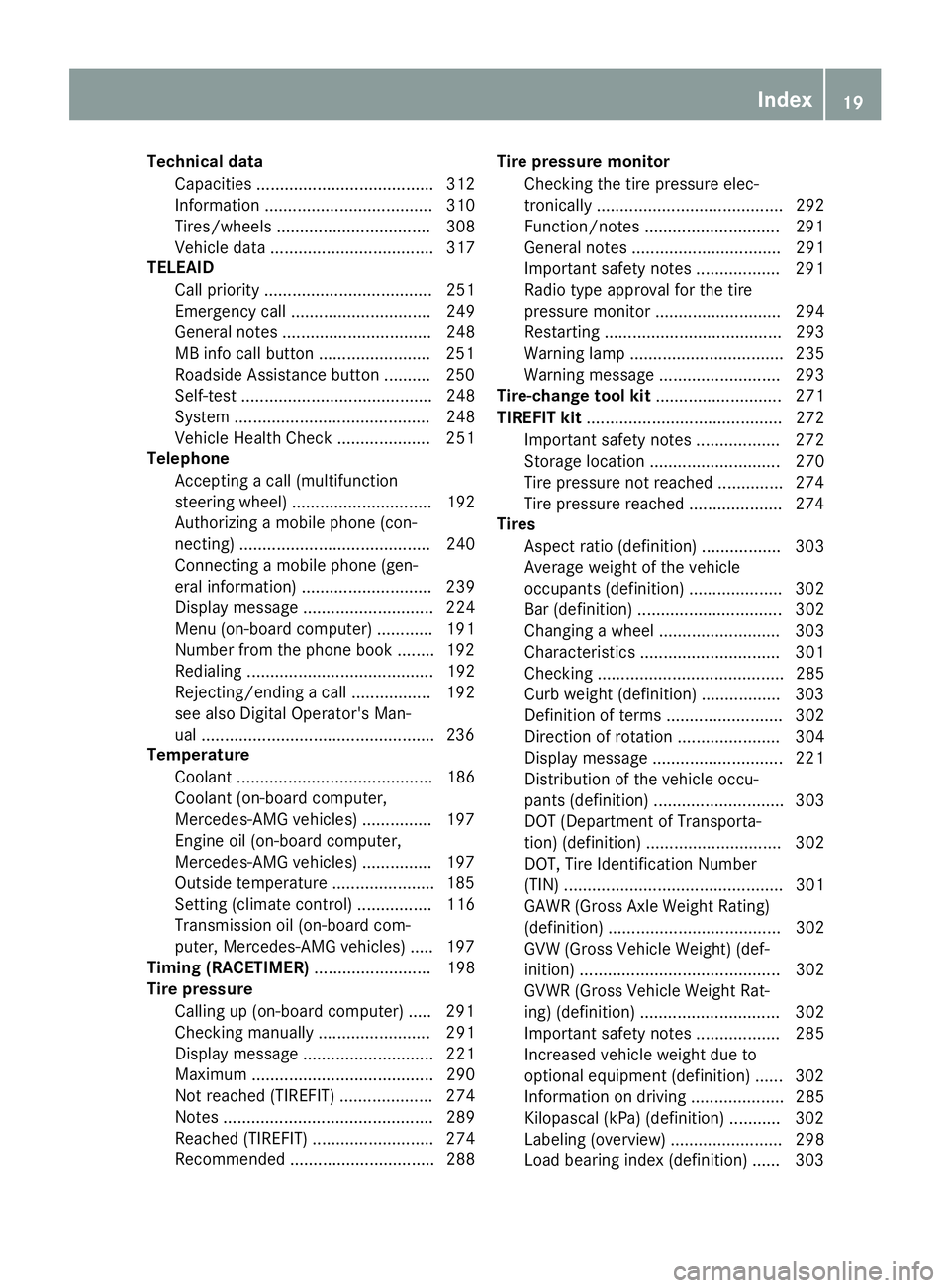
Technical dataCapacities ...................................... 312
Information .................................... 310
Tires/wheels ................................. 308
Vehicle data ................................... 317
TELEAID
Call priority .................................... 251
Emergency call .............................. 249
General notes ................................ 248
MB info call button ........................2 51
Roadside Assistance button .......... 250
Self-test ......................................... 248
System .......................................... 248
Vehicle Health Check .................... 251
Telephone
Accepting a call (multifunction
steering wheel) .............................. 192
Authorizing a mobile phone (con-
necting) ......................................... 240
Connecting a mobile phone (gen-
eral information) ............................ 239
Display message ............................ 224
Menu (on-board computer) ............ 191
Number from the phone book ........1 92
Redialing ........................................ 192
Rejecting/ending a call ................. 192
see also Digital Operator's Man-
ual ..................................................2 36
Temperature
Coolant .......................................... 186
Coolant (on-board computer,
Mercedes-AMG vehicles) ...............1 97
Engine oil (on-board computer,
Mercedes-AMG vehicles) ...............1 97
Outside temperature ......................1 85
Setting (climate control) ................ 116
Transmission oil (on-board com-
puter, Mercedes-AMG vehicles) ..... 197
Timing (RACETIMER) ......................... 198
Tire pressure
Calling up (on-board computer) ..... 291
Checking manually ........................ 291
Display message ............................ 221
Maximum ....................................... 290
Not reached (TIREFIT) .................... 274
Notes ............................................. 289
Reached (TIREFIT) .......................... 274
Recommended ............................... 288 Tire pressure monitor
Checking the tire pressure elec-
tronically ........................................ 292
Function/notes .............................2 91
Genera
l notes ................................ 291
Important safety notes .................. 291
Radio type approval for the tire
pressure monitor ........................... 294
Restarting ...................................... 293
Warning lamp ................................. 235
Warning message .......................... 293
Tire-change tool kit ........................... 271
TIREFIT kit .......................................... 272
Important safety notes .................. 272
Storage location ............................ 270
Tire pressure not reached .............. 274
Tire pressure reached .................... 274
Tires
Aspect ratio (definition) ................. 303
Average weight of the vehicle
occupants (definition) .................... 302
Bar (definition) ............................... 302
Changing a wheel .......................... 303
Characteristics .............................. 301
Checking ........................................ 285
Curb weight (definition) ................. 303
Definition of terms ......................... 302
Direction of rotation ...................... 304
Display message ............................ 221
Distribution of the vehicle occu-
pants (definition) ............................ 303
DOT (Department of Transporta-
tion) (definition) ............................. 302
DOT, Tire Identification Number
(TIN) ............................................... 301
GAWR (Gross Axle Weight Rating)
(definition) ..................................... 302
GVW (Gross Vehicle Weight) (def-
inition) ........................................... 302
GVWR (Gross Vehicle Weight Rat-
ing) (definition) .............................. 302
Important safety notes .................. 285
Increased vehicle weight due to
optional equipment (definition) ...... 302
Information on driving .................... 285
Kilopascal (kPa) (definition) ........... 302
Labeling (overview) ........................ 298
Load bearing index (definition) ...... 303
Index19
Page 141 of 322
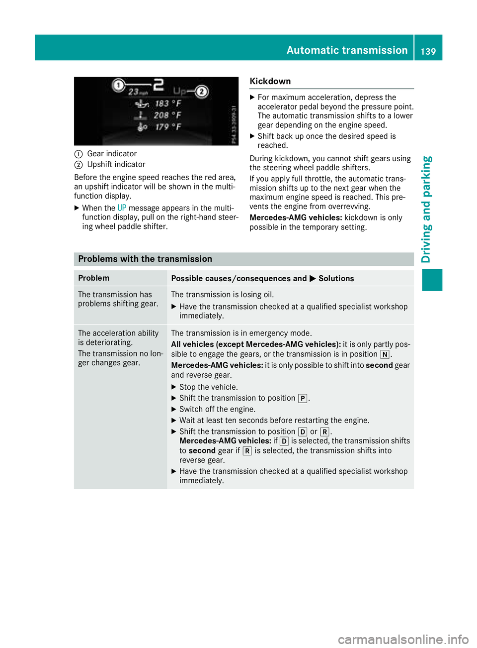
:Gear indicator
;Upshift indicator
Before the engine speed reaches the red area,
an upshift indicator will be shown in the multi-
function display.
XWhen the UPmessage appears in the multi-
function display, pull on the right-hand steer-
ing wheel paddle shifter.
Kickdown
XFor maximum acceleration, depress the
accelerator pedal beyond the pressure point. The automatic transmission shifts to a lower
gear depending on the engine speed.
XShift back up once the desired speed is
reached.
During kickdown, you cannot shift gears using
the steering wheel paddle shifters.
If you apply full throttle, the automatic trans-
mission shifts up to the next gear when the
maximum engine speed is reached. This pre-
vents the engine from overrevving.
Mercedes-AMG vehicles: kickdown is only
possible in the temporary setting.
Problems with the transmission
ProblemPossible causes/consequences and MSolutions
The transmission has
problems shifting gear.The transmission is losing oil.
XHave the transmission checked at a qualified specialist workshop
immediately.
The acceleration ability
is deteriorating.
The transmission no lon-
ger changes gear.The transmission is in emergency mode.
All vehicles (except Mercedes-AMG vehicles): it is only partly pos-
sible to engage the gears, or the transmission is in position i.
Mercedes-AMG vehicles: it is only possible to shift into secondgear
and reverse gear.
XStop the vehicle.
XShift the transmission to position j.
XSwitch off the engine.
XWait at least ten seconds before restarting the engine.
XShift the transmission to position hork.
Mercedes-AMG vehicles: ifh is selected, the transmission shifts
to second gear ifkis selected, the transmission shifts into
reverse gear.
XHave the transmission checked at a qualified specialist workshop
immediately.
Automatic transmission139
Driving and parking
Z
Page 262 of 322
GWARNING
If engine oil comes into contact with hot com- ponents in the engine compartment, it may
ignite. There is a risk of fire and injury.
Make sure that engine oil is not spilled next to
the filler neck. Let the engine cool down and
thoroughly clean the engine oil off the com-
ponents before starting the engine.
HEnvironmental note
When adding oil, take care not to spill any. If
oil enters the soil or waterways, it is harmful to
the environment.
!Use only engine oils and oil filters that are
approved for vehicles with a service system. A list of the engine oils and oil filters that have
been tested and approved in accordance with
Mercedes-Benz Specifications for Service
Products is available at any authorized
Mercedes-Benz Center.
The following cause engine failure or damage
to the exhaust system:
RUse of engine oils and oil filters that have
not been expressly approved for the service
system
RReplacement of engine oil and oil filter after
the replacement interval specified by the
service system has expired
RUse of engine oil additives
!Do not add too much oil. If the oil level is
above the "max" mark on the dipstick, too
much oil has been added. This can lead to
damage to the engine or the catalytic con-
verter. Have excess oil siphoned off.
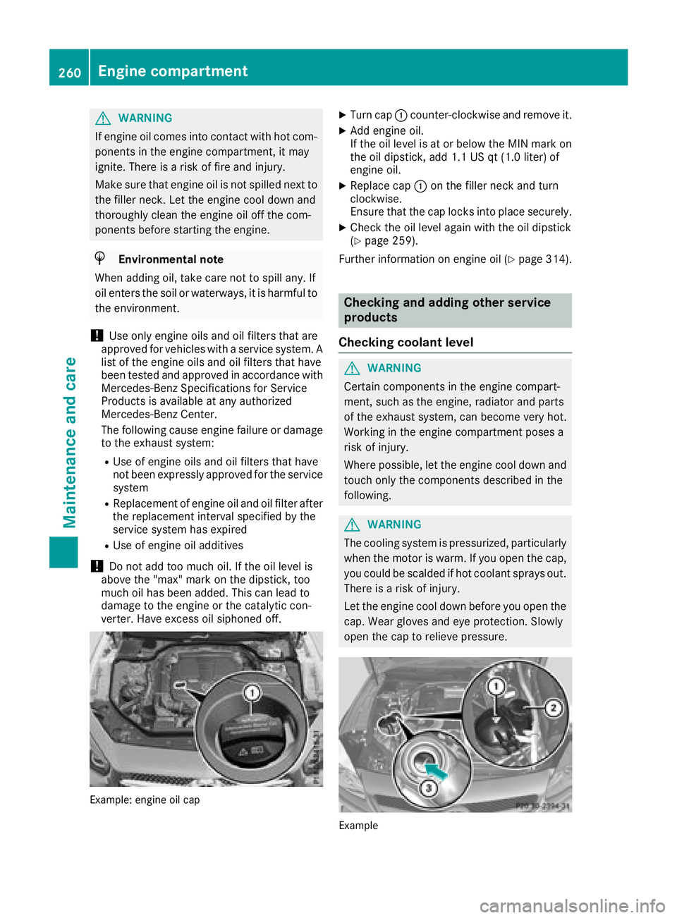
Example: engine oil cap
XTurn cap :counter-clockwise and remove it.
XAdd engine oil.
If the oil level is at or below the MIN mark on
the oil dipstick, add 1.1 US qt (1.0 liter) of
engine oil.
XReplace cap :on the filler neck and turn
clockwise.
Ensure that the cap locks into place securely.
XCheck the oil level again with the oil dipstick
(Ypage 259).
Further information on engine oil (
Ypage 314).
Checking and adding other service
products
Checking coolant level
GWARNING
Certain components in the engine compart-
ment, such as the engine, radiator and parts
of the exhaust system, can become very hot.
Working in the engine compartment poses a
risk of injury.
Where possible, let the engine cool down and touch only the components described in the
following.
GWARNING
The cooling system is pressurized, particularly
when the motor is warm. If you open the cap,
you could be scalded if hot coolant sprays out.
There is a risk of injury.
Let the engine cool down before you open the
cap. Wear gloves and eye protection. Slowly
open the cap to relieve pressure.
Example
260Engine compartment
Maintenance and care
Page 263 of 322
XPark the vehicle on a level surface.
Only check the coolant level when the vehicleis on a level surface and the engine has cooled
down.
XTurn the SmartKey to position 2in the igni-
tion lock (Ypage 122).
On vehicles with KEYLESS-GO, press the
Start/Stop button twice (
Ypage 122).
XCheck the coolant temperature gage in the
multifunction display.
The coolant temperature must be below
158 ‡ (70 †).
XTurn the SmartKey to position u
(Ypage 122) in the ignition lock.
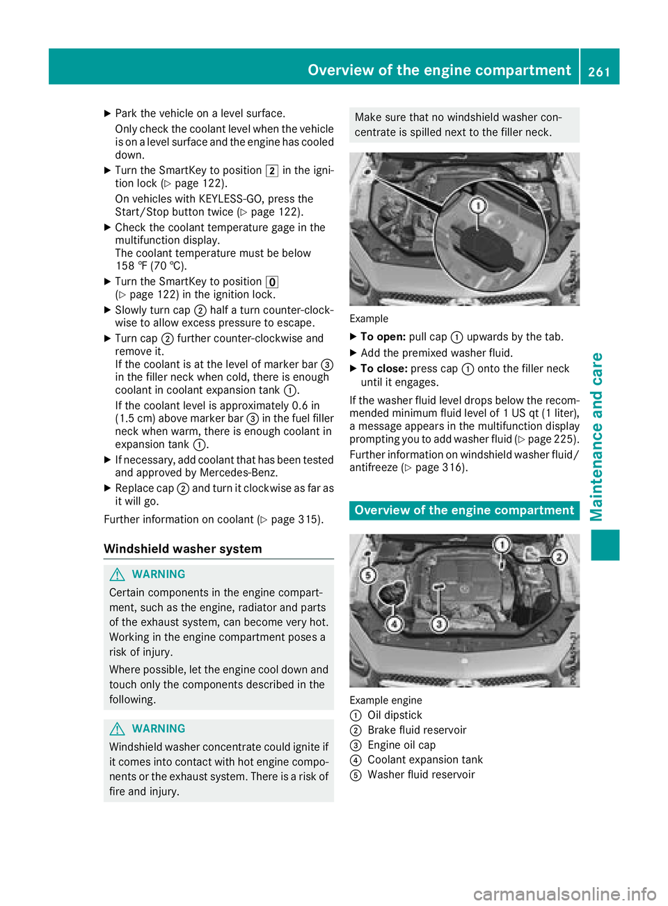
XSlowly turn cap ;half a turn counter-clock-
wise to allow excess pressure to escape.
XTurn cap ;further counter-clockwise and
remove it.
If the coolant is at the level of marker bar =
in the filler neck when cold, there is enough
coolant in coolant expansion tank :.
If the coolant level is approximately 0.6 in
(1.5 cm) above marker bar =in the fuel filler
neck when warm, there is enough coolant in
expansion tank :.
XIf necessary, add coolant that has been tested
and approved by Mercedes-Benz.
XReplace cap;and turn it clockwise as far as
it will go.
Further information on coolant (
Ypage 315).
Windshield washer system
GWARNING
Certain components in the engine compart-
ment, such as the engine, radiator and parts
of the exhaust system, can become very hot.
Working in the engine compartment poses a
risk of injury.
Where possible, let the engine cool down and touch only the components described in the
following.
GWARNING
Windshield washer concentrate could ignite if it comes into contact with hot engine compo-
nents or the exhaust system. There is a risk of
fire and injury.
Make sure that no windshield washer con-
centrate is spilled next to the filler neck.
Example
XTo open: pull cap:upwards by the tab.
XAdd the premixed washer fluid.
XTo close: press cap :onto the filler neck
until it engages.
If the washer fluid level drops below the recom-
mended minimum fluid level of 1 US qt (1 liter),
a message appears in the multifunction display
prompting you to add washer fluid (
Ypage 225).
Further information on windshield washer fluid/
antifreeze (
Ypage 316).
Overview of the engine compartment
Example engine
:
Oil dipstick
;Brake fluid reservoir
=Engine oil cap
?Coolant expansion tank
AWasher fluid reservoir
Overview of the engine compartment261
Maintenance and care
Z
Page 266 of 322
!Make sure that:
Rthe side windows and the roof are com-
pletely closed
Rthe climate control blower is switched off
Rthe windshield wiper switch is at position0
The vehicle could otherwise be damaged.
You can clean the vehicle at an automatic car
wash from the very start.
Preferably clean the vehicle at automatic car
washes that use textile washing elements with-
out brushes. This prevents fine scratches from
forming on the paintwork and film.
If the vehicle is very dirty, pre-wash it before
cleaning it in an automatic car wash.
After using an automatic car wash, wipe off wax
from the windshield and the wiper blades. This
will prevent smears and reduce wiping noises
caused by residue on the windshield.
iVehicles with decorative film: select a wash
program without hot wax at the automatic car
wash.
Washing by hand
In some countries, washing by hand is only
allowed at specially equipped washing bays.
Observe the legal requirements in each country.
XDo not use hot water and do not wash the
vehicle in direct sunlight.
XUse a soft sponge to clean.
XUse a mild cleaning agent, such as a car
shampoo approved by Mercedes-Benz.
XThoroughly hose down the vehicle with a gen-
tle jet of water.
XDo not point the water jet directly towards the
air inlet or the edges of decorative foils.
XUse plenty of water and rinse out the sponge
frequently.
XRinse the vehicle with clean water and dry
thoroughly with a chamois.
XDo not let the cleaning agent dry on the paint- work or the decorative foils.
Carefully remove all deposits of road salt as
soon as possible when driving in winter.
Power washers
GWARNING
The water jet from a circular jet nozzle (dirt
blasters) can cause invisible exterior damage
to the tires or chassis components. Compo-
nents damaged in this way may fail unexpect-
edly. There is a risk of an accident.
Do not use power washers with circular jet
nozzles to clean the vehicle. Have damaged
tires or chassis components replaced imme-
diately.
!Vehicles with decorative foil: parts of your
vehicle are covered with decorative foil. Main-
tain a distance of at least 27.5 in (70 cm)
between the foil-wrapped parts of the vehicle
and the nozzle of the high pressure cleaner.
Information about the correct distance is
available from the equipment manufacturer.
Move the power washer nozzle around when
cleaning your vehicle.
The water temperature of the high-pressure
cleaner must not exceed 140 °F (60 °C).
!Always maintain a distance of at least
11.8 in (30 cm) between the vehicle and the
power washer nozzle. Information about the
correct distance is available from the equip-
ment manufacturer.
Move the power washer nozzle around when
cleaning your vehicle.
Do not aim directly at any of the following:
Rtires
Rdoor gaps, roof gaps, joints, etc.
Relectrical components
Rbattery
Rplug-type couplings
Rlights
Rseals
Rtrim
Rventilation slots
Damaged seals or electrical components can
lead to leaks or failures.
264Care
Maintenance and care
Page 276 of 322
Do not switch off thetire inflation com -
pressor during this phase .
XLet thetire inflation compressor run for a
maximum of fiv eminutes. The tire should then
hav eattained apressur eof at least 18 0kP a
(1. 8bar/2 6psi) .
If atire pressur eof 18 0kP a(1. 8bar/26 psi) has
been attained after fiv eminutes: (
Ypage 274).
If atire pressur eof 18 0kP a(1. 8bar/26 psi) has
no tbeen attained after fiv eminutes:
(
Ypage 274).
If tire sealant has escaped, clean it off affecte d
area sas quickl yas possible. Use plain water if
possible.
If your clothes are soiled wit htire sealant ,hav e
them cleane dwit hperchloroethylen eat adry
cleane ras soo nas possible.
Ti re pressure not reached
Ifapressur eof 18 0kP a(1. 8bar/26 psi) has no t
been attained after fiv eminutes:
XSwitc hoff th etire inflation compressor.
XUnscrew th efiller hos efrom th evalv eof th e
fault ytire.
Not ethat tire sealant may escape when you
unscrew th efiller hose.
XVer yslowly drive forward sor revers eapprox -
imately 30 ft (10 m).
XPump up th etire again .
Afte r amaximum of fiv eminute sth etire pres-
sur emus tbe at least 18 0kP a(1. 8bar/
26 psi) .
GWARNIN G
If th erequire dtire pressur eis no treached
after th especified time, th etire is to obadly
damaged. The tire sealant canno trepair th e
tire in this instance .Damaged tires and atire
pressur ethat is to olow can significantly
impair th evehicle's braking and drivin gchar-
acteristics .There is aris kof accident.
Do no tcontinu edriving. Contac t aqualified
specialist workshop .
Tire pressure reached
GWARNING
A tire temporarily seale dwit htire sealant
impairs th edrivin gcharacteristics and is no t
suitable for higher speeds .There is aris kof
accident.
You should therefor eadapt your drivin gstyle
accordingly and drive carefully. Do no texceed
th especified maximum speed wit h atire that
has been repaire dusin gtire sealant .
The maximum speed for atire seale dwit htire
sealant is 50 mph (80 km/h). The upper part of
th eTIREFI Tsticker mus tbe affixe dto th einstru-
men tcluste rin th edriver's field of vision .
!Residue from thetire sealant may come out
of th efiller hos eafter use. This could caus e
stains.
Therefore ,plac eth efiller hos ein th eplastic
bag whic hcontained th eTIREFI Tkit.
HEnvironmenta lnot e
Hav eth eused tire sealant bottl edispose dof
professionally, e.g. at aqualified specialist
workshop .
If atire pressur eof 18 0kP a(1.8 bar/26 psi) has
been achieved after a maximum period of ten
minutes:
XSwitch off the tire inflation compressor.
XUnscrew the filler hose from the valve of the
faulty tire.
XStow the tire sealant bottle and the tire infla-
tion compressor.
XPull away immediately.
XStop after driving for approximately ten
minutes and check the tire pressure with the
tire inflation compressor.
The tire pressure must now be at least
130 kPa (1.3 bar/19 psi).
GWARNING
If the required tire pressure is not reached
after driving for a short period, the tire is too
badly damaged. The tire sealant cannot repair
the tire in this instance. Damaged tires and a
tire pressure that is too low can significantly
274Flat tire
Breakdown assistance
Page 305 of 322
Curb weight
The weight of a vehicle with standard equipment
including the maximum capacity of fuel, oil and
coolant. It also includes the air-conditioning sys-
tem and optional equipment if these are instal-
led in the vehicle, but does not include passen-
gers or luggage.
Maximum load rating
The maximum load rating is the maximum per-
missible weight in kilograms or lbs for which a
tire is approved.
Maximum permissible tire pressure
Maximum permissible tire pressure for one tire.
Maximum load on one tire
Maximum load on one tire. This is calculated by
dividing the maximum axle load of one axle by
two.
PSI (pounds per square inch)
A standard unit of measure for tire pressure.
Aspect ratio
Relationship between tire height and tire width
in percent.
Tire pressure
This is pressure inside the tire applying an out-
ward force to each square inch of the tire's sur-
face. The tire pressure is specified in pounds per
square inch (psi), in kilopascal (kPa) or in bar.
The tire pressure should only be corrected when
the tires are cold.
Cold tire pressure
The tires are cold:
Rif the vehicle has been parked with the tires
out of direct sunlight for at least three hours
and
Rif the vehicle has not been driven further than
1 mile (1.6 km)
Tread
The part of the tire that comes into contact with
the road.
Bead
The tire bead ensures that the tire sits securely
on the wheel. There are several steel wires in the
bead to prevent the tire from coming loose from the wheel rim.
Sidewall
The part of the tire between the tread and the
bead.
Weight of optional extras
The combined weight of those optional extras
that weigh more than the replaced standard
parts and more than 2.3 kg (5 lbs).Thes e
option al extras, such as high-performance
brakes, level control, a roof rack or a high-per-
formance battery, are not included in the curb
weight and the weight of the accessories.
TIN (Tire Identification Number)
This is a unique identifier which can be used by
a tire manufacturer to identify tires, for example
for a product recall, and thus identify the pur-
chasers. The TIN is made up of the manufactur-
er's identity code, tire size, tire type code and
the manufacturing date.
Load bearing index
The load bearing index (also load index) is a code
that contains the maximum load bearing capa-
city of a tire.
Traction
Traction is the result of friction between the tires
and the road surface.
Treadwear indicators
Narrow bars (tread wear bars) that are distrib-
uted over the tire tread. If the tire tread is level
with the bars, the wear limit of áin (1.6 mm)
has been reached.
Occupant distribution
The distribution of occupants in a vehicle at their
designated seating positions.
Total load limit
Nominal load and luggage load plus 68 kg
(150 lbs) multiplied by the number of seats in
the vehicle.
Changing a wheel
Flat tire
The "Breakdown assistance" section
(Ypage 271) contains information and notes on
how to deal with a flat tire. Information on driv-
ing with MOExtended tires in the event of a flat
Changing a wheel303
Wheels and tires
Z
Page 306 of 322
tire can be found under "MOExtended tires (tires
with run-flat characteristics" (Ypage 271).
Rotating the wheels
GWARNING
Interchanging the front and rear wheels may
severely impair the driving characteristics if
the wheels or tires have different dimensions. The wheel brakes or suspension components
may also be damaged. There is a risk of acci-
dent.
Rotate front and rear wheels only if the wheels and tires are of the same dimensions.
!On vehicles equipped with a tire pressure
monitor, electronic components are located
in the wheel.
Tire-mounting tools should not be used near
the valve. This could damage the electronic
components.
Only have tires changed at a qualified spe-
cialist workshop.
Always pay attention to the instructions and
safety notes when changing a wheel
(
Ypage 304).
The wear patterns on the front and rear tires
differ, depending on the operating conditions.
Rotate the wheels before a clear wear pattern
has formed on the tires. Front tires typically
wear more on the shoulders and the rear tires in
the center.
On vehicles that have the same size front and
rear wheels, you can rotate the wheels accord-
ing to the intervals in the tire manufacturer's
warranty book in your vehicle documents. If no
warranty book is available, the tires s
hould be
rotated every 3,000 to 6,000 miles (5,000 to
10,000 km). Depending on tire wear, this may
be required earlier. Do not change the direction
of wheel rotation.
Clean the contact surfaces of the wheel and the
brake disc thoroughly every time a wheel is rota- ted. Check the tire pressure and reactivate the
tire pressure monitor if necessary.
Direction of rotation
Tires with a specified direction of rotation have
additional benefits, e.g. if there is a risk of hydro- planing. These advantages can only be gained if
the tires are installed corresponding to the
direction of rotation.
An arrow on the sidewall of the tire indicates its
correct direction of rotation.
Storing wheels
Store wheels that are not being used in a cool,
dry and preferably dark place. Protect the tires
from oil, grease, gasoline and diesel.
Mounting a wheel
Preparing the vehicle
XStop the vehicle on solid, non-slippery and
level ground.
XUnload the vehicle. The jack can only be used
when the vehicle is unladen.
XApply the electric parking brake manually.
XBring the front wheels into the straight-ahead
position.
XShift the transmission to position j.
XSwitch off the engine.
XVehicles without KEYLESS-GO:remove the
SmartKey from the ignition lock.
XVehicles with KEYLESS-GO: open the driv-
er's door.
The vehicle electronics now have status 0.
This is the same as the SmartKey having been
removed.
XVehicles with KEYLESS-GO: remove the
Start/Stop button from the ignition lock
(
Ypage 122).
XIf included in the vehicle equipment, remove
the tire-change tool kit from the vehicle.
XSafeguard the vehicle against rolling away.
304Changing a wheel
Wheels an d tires