2018 MERCEDES-BENZ SL ROADSTER load capacity
[x] Cancel search: load capacityPage 22 of 322
 ................... 302
M+S tires ....................................... 287
Maximum load on a tire (defini-
tion) ........")
Load index .....................................300
Load index (definition) ................... 302
M+S tires ....................................... 287
Maximum load on a tire (defini-
tion) ............................................... 303
Maximum loaded vehicle weight
(definition) ..................................... 302
Maximum permissible tire pres-
sure (definition) .............................3 03
Maximum tire load ......................... 301
Maximum tire load (definition) ....... 303
MOExtended tires .......................... 287
Optional equipment weight (defi-
nition) ............................................ 303
Overview ........................................ 285
PSI (pounds per square inch) (def-
inition) ...........................................3 03
Replacing ....................................... 304
Service life ..................................... 286
Sidewall (definition) ....................... 303
Speed rating (definition) ................ 302
Storing ...........................................3 04
Structure and characteristics
(definition) ..................................... 302
Summer tires ................................. 287
Temperature .................................. 298
TIN (Tire Identification Number)
(definition) ..................................... 303
Tire bead (definition) ......................3 03
Tire pressure (definition) ................ 303
Tire pressures (recommended) ...... 302
Tire size (data) ............................... 308
Tire size designation, load-bearing
capacity, speed rating .................... 298
Tire tread ....................................... 286
Tire tread (definition) ..................... 303
Total load limit (definition) ............. 303
Traction ......................................... 297
Traction (definition) ....................... 303
Tread wear ..................................... 297
Uniform Tire Quality Grading
Standards ...................................... 297
Uniform Tire Quality Grading
Standards (definition) .................... 302
Wear indi
cator (definition) ............. 303
Wheel and tire combination ........... 308
Wheel rim (definition) .................... 302
see Flat tire Tow-starting
Emergency engine starting ............ 282
Important safety notes .................. 280
Towing away
Important safety guidelines ........... 280
Installing the towing eye ................ 281
Removing the towing eye ............... 281
Transporting the vehicle ................ 282
With both axles on the ground ....... 281
With the rear axle raised ................ 282
Traffic reports
see also Digital Operator's Man-
ual .................................................. 236
Traffic Sign Assist
Display message ............................ 216
Transmission
Selector lever ................................ 130
see Automatic transmission
Transmission position display ......... 131
Transporting the vehicle .................. 282
Trip computer (on-board com-
puter) .................................................. 188
Trip odometer
Calling up ....................................... 188
Resetting (on-board computer) ...... 189
Trunk
Emergency release .......................... 85
Important safety notes .................... 80
Locking separately ........................... 84
Opening/closing (automatically
from inside) ...................................... 84
Opening/closing (automatically
from outside) ................................... 82
Opening/closing (from outside,
HANDS-FREE ACCESS) .................... 82
Opening/closing (manually from
outside) ............................................ 81
Overview .......................................... 80
Power closing .................................. 80
Trunk lid
Display message ............................ 224
Opening dimensions ...................... 317
Trunk partition
Display message ............................ 224
General notes .................................. 91
Installing .......................................... 91
Opening/closing .............................. 91
Removing ......................................... 91
20Index
Page 273 of 322
.
:Bag containing the tire-changing tools
Bag :with the tire-changing tools contains:
Rj")
Tire-change tool kit
The tire-change tool kit can be found in the
stowage well under the trunk floor (Ypage 245).
:Bag containing the tire-changing tools
Bag :with the tire-changing tools contains:
Rjack
Rlug wrench
Ralignment bolt
Rwheel chock
Rgloves
Depending on the equipment, tools required for
a wheel change, such as a jack or a lug wrench, are not available in all vehicles. Tools approved
for your vehicle are available at a qualified spe-
cialist workshop.
Flat tire
Preparing the vehicle
Your vehicle may be equipped with:
Rtires with run-flat characteristics
(MOExtended tires) (Ypage 271)
Vehicle preparation is not necessary on vehi-
cles with MOExtended tires.
Ra TIREFIT kit (Ypage 270)
Vehicles with the Mercedes-Benz emer-
gency call system: in the event of a flat tire, you
can contact the Mercedes-Benz emergency call
system customer center.
Vehicles equipped with MOExtended tires are
not equipped with a TIREFIT kit at the factory. It
is therefore recommended that you additionally
equip your vehicle with a TIREFIT kit if you mount tires that do not feature run-flat characteristics,
e.g. winter tires. A TIREFIT kit may be obtained
from a qualified specialist workshop. Information on changing and mounting wheels
(
Ypage 303).
XStop the vehicle on solid, non-slippery and
level ground, as far away as possible from
traffic.
XSwitch on the hazard warning lamps.
XSecure the vehicle against rolling away
(Ypage 142).
XIf possible, bring the front wheels into the
straight-ahead position.
XSwitch off the engine.
XVehicles without KEYLESS-GO:
remove the
SmartKey from the igniti on lock.
XVehicles with KEYLESS-GO: open the driv-
er's door.
The vehicle electronics now have status 0.
This is the same as the SmartKey having been
removed.
XVehicles with KEYLESS-GO: remove the
Start/Stop button from the ignition lock
(
Ypage 122).
XMake sure that the passengers are not endan-
gered as they do so. Make sure that no one is near the danger area while a wheel is being
changed. Anyone who is not directly assisting
in the wheel change should, for example,
stand behind the barrier.
XGet out of the vehicle. Pay attention to traffic
conditions when doing so.
XClose the driver's door.
MOExtended tires (tires with run-flat
properties)
General notes
With MOExtended tires (tires with run flat char-
acteristics), you can continue to drive your vehi-
cle even if there is a total loss of pressure in one
or more tires. The affected tire must not show
any clearly visible damage.
You can recognize a MOExtended tire by the
MOExtended marking which appears on the
sidewall of the tire. You will find this marking
next to the tire size designation, the load-bear-
ing capacity and the speed index (
Ypage 298).
MOExtended tires may only be used in conjunc-
tion with an active tire pressure monitor.
Flat tire271
Breakdown assistance
Page 298 of 322

iThe specifications shown on the Tire and
Loading Information placard in the illustration
are examples. The number of seats is vehicle-
specific and can differ from the details shown.
The number of seats in your vehicle can be
found on the Tire and Loading Information
placard.
Determining the correct load limit
Step-by-step instructions
The following steps have been developed as
required of all manufacturers under Title 49,
Code of U.S. Federal Regulations, Part 575 pur-
suant to the "National Traffic and Motor Vehicle
Safety Act of 1966".
XStep 1: Locate the statement "The combined
weight of occupants and cargo should never
exceed XXX kg or XXX lbs." on your vehicle’s
Tire and Loading Information placard.
XStep 2: Determine the combined weight of
the driver and passengers that will be riding in your vehicle.
XStep 3: Subtract the combined weight of the
driver and passengers from XXX kilograms or
XXX lbs.
XStep 4: The resulting figure equals the avail-
able amount of cargo and luggage load capa-
city. For example, if the "XXX" amount equals
1400 lbs and there will be five 150-lb pas-
sengers in your vehicle, the amount of avail-
able cargo and luggage load capacity is
650 lbs (1400 - 750 (5 x 150) = 650 lbs).
XStep 5: Determine the combined weight of
luggage and cargo being loaded on the vehi-
cle. That weight may not safely exceed the
available cargo and luggage load capacity cal- culated in step 4.
Example: steps 1 to 3
The following table shows examples on how to
calculate total and cargo load capacities with
varying seating configurations and number and
size of occupants. The following examples use a
load limit of 1500 lbs (680 kg). This is for illus-
tration purposes only. Make sure you are
using the actual load limit for your vehicle stated
on your vehicle's Tire and Loading Information
placard (
Ypage 295). The greater the combined weight of the occu-
pants, the lower the maximum luggage load.
Step 1
Example 1Example 2
Combined max-
imum weight of
occupants and
cargo (data
from the Tire
and Loading
Information
placard)1500 lbs
(680 kg)1500 lbs
(680 kg)
Step 2
Example 1Example 2
Number of peo-
ple in the vehi-
cle (driver and
occupants)12
Weight of the
occupantsOccu-
pant 1:
175 lbs
(80 kg)Occu-
pant 1:
175 lbs
(80 kg)
Occu-
pant 2:
195 lbs
(88 kg)
Gross weight
of all occupants175 lbs
(80 kg)370 lbs
(168 kg)
Step 3
Example 1Example 2
Permissible
load (maxi-
mum gross
vehicle weight
rating from the
Tire and Load-
ing Information
placard minus
the gross
weight of all
occupants)1500 lbs
(680 kg)
Ò
175 lbs
(80 kg) =
1325 lbs
(600 kg)1500 lbs
(680 kg) Ò
370 lbs
(168 kg) =
1130 lbs
(512 kg)
296Loading the vehicle
Wheels and tires
Page 300 of 322
 on all four winter tires.
Observe the le")
You should pay special attention to road condi-
tions when temperatures are around freezing
point.
Mercedes-Benz recommends a minimum tread
depth ofãin (4 mm) on all four winter tires.
Observe the legally required minimum tire tread
depth (
Ypage 286). Winter tires can reduce the
braking distance on snow-covered surfaces in
comparison with summer tires. The braking dis-
tance is still much further than on surfaces that
are not icy or covered with snow. Take appro-
priate care when driving.
Temperature
GWARNING
The temperature grade for this tire is estab-
lished for a tire that is properly inflated and
not overloaded. Excessive speed, underinfla-
tion, or excessive loading, either separately or
in combination, can cause excessive heat
build-up and possible tire failure.
The temperature grades are A (the highest), B,
and C, representing the tire's resistance to the
generation of heat and its ability to dissipate
heat when tested under controlled conditions
on a specified indoor laboratory test wheel. Sus-
tained high temperature can cause the material
of the tire to degenerate and reduce tire life, and
excessive temperature can lead to sudden tire
failure. The grade C corresponds to a level of
performance which all passenger car tires must
meet under the Federal Motor Vehicle Safety
Standard No. 109. Grades B and A represent
higher levels of performance on the laboratory
test wheel than the minimum required by law.
Tire labeling
Overview
:Uniform Tire Quality Grading Standard
(Ypage 302)
;DOT, Tire Identification Number
(Ypage 301)
=Maximum tire load (Ypage 301)
?Maximum tire pressure (Ypage 290)
AManufacturer
BTire material (Ypage 301)
CTire size designation, load-bearing capacity
and speed rating (Ypage 298)
DLoad index (Ypage 300)
ETire name
The markings described above are on the tire in
addition to the tire name (sales designation) and
the manufacturer's name.
iTire data is vehicle-specific and may deviate
from the data in the example.
Tire size designation, load-bearing
capacity and speed rating
GWARNING
Exceeding the stated tire load-bearing capa-
city and the approved maximum speed could
lead to tire damage or the tire bursting. There is a risk of accident.
Therefore, only use tire types and sizes
approved for your vehicle model. Observe the
298All about wheels and tires
Wheels and tires
Page 301 of 322
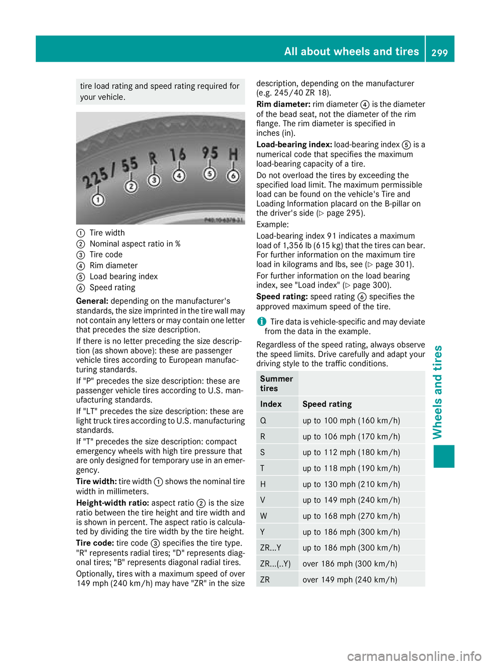
tire load rating and speed rating required for
your vehicle.
:Tire width
;Nominal aspect ratio in %
=Tire code
?Rim diameter
ALoad bearing index
BSpeed rating
General: depending on the manufacturer's
standards, the size imprinted in the tire wall may
not contain any letters or may contain one letter
that precedes the size description.
If there is no letter preceding the size descrip-
tion (as shown above): these are passenger
vehicle tires according to European manufac-
turing standards.
If "P" precedes the size description: these are
passenger vehicle tires according to U.S. man-
ufacturing standards.
If "LT" precedes the size description: these are
light truck tires according to U.S. manufacturing
standards.
If "T" precedes the size description: compact
emergency wheels with high tire pressure that
are only designed for temporary use in an emer-
gency.
Tire width: tire width:shows the nominal tire
width in millimeters.
Height-width ratio: aspect ratio;is the size
ratio between the tire height and tire width and
is shown in percent. The aspect ratio is calcula-
ted by dividing the tire width by the tire height.
Tire code: tire code=specifies the tire type.
"R" represents radial tires; "D" represents diag-
ona l ti
res; "B" represents diagonal radial tires.
Optionally, tires with a maximum speed of over
149 mph (240 km/h) may have "ZR" in the size description, depending on the manufacturer
(e.g. 245/40 ZR 18).
Rim diameter:
rim diameter?is the diameter
of the bead seat, not the diameter of the rim
flange. The rim diameter is specified in
inches (in).
Load-bearing index: load-bearing indexAis a
numerical code that specifies the maximum
load-bearing capacity of a tire.
Do not overload the tires by exceeding the
specified load limit. The maximum permissible
load can be found on the vehicle's Tire and
Loading Information placard on the B-pillar on
the driver's side (
Ypage 295).
Example:
Load-bearing index 91 indicates a maximum
load of 1,356 lb (615 kg) that the tires can bear.
For further information on the maximum tire
load in kilograms and lbs, see (
Ypage 301).
For further information on the load bearing
index, see "Load index" (
Ypage 300).
Speed rating: speed ratingBspecifies the
approved maximum speed of the tire.
iTire data is vehicle-specific and may deviate
from the data in the example.
Rega rdle
ss of the speed rating, always observe
the speed limits. Drive carefully and adapt your
driving style to the traffic conditions.
Summer
tires
IndexSpeed rating
Qup to 100 mph (160 km/h)
Rup to 106 mph (170 km/h)
Sup to 112 mph (180 km/h)
Tup to 118 mph (190 km/h)
Hup to 130 mph (210 km/h)
Vup to 149 mph (240 km/h)
Wup to 168 mph (270 km/h)
Yup to 186 mph (300 km/h)
ZR...Yup to 186 mph (300 km/h)
ZR...(..Y)over 186 mph (300 km/h)
ZRover 149 mph (240 km/h)
All about wheels an d tires299
Wheels and tires
Z
Page 304 of 322

Definition of termsfor tire san dloading
Tire pl ycomposition an dmaterial used
Describes th enumber of plie sor th enumber of
layer sof rubber-coated fabric in th etire tread
and sidewall .These are mad eof steel, nylon ,
polyester and other materials.
Ba r
Metric uni tfo rtire pressure. 14.503 8pounds
per square inch (psi) and 10 0kilopascals (kPa)
are th eequivalen tof 1bar .
DOT (Department of Transportation)
DOT-marke dtires fulfill th erequirements of th e
U S Departmen tof Transportation .
Normal occupant weigh t
The number of occupantsfo rwhic hth evehicle
is designed multiplie dby 68 kilogram s(15 0lbs) .
Unifor mTire Quality Grading Standard s
Auniform standard to grade th equalit yof tires
wit hregard sto tread quality, tire traction and
temperature characteristics .The qualit ygrad-
in g assessmen tis mad eby th emanufacturer
followin gspecification sfrom th eU.S. govern -
ment. The ratings are molded into th esidewall of
th etire.
Recommended tire pressure s
The recommended tire pressure applies to th e
tires mounted at th efactory.
The Tir eand Loadin gInformation placard con-
tain sth erecommended tire pressures fo rcold
tires on
afu
ll yloaded vehicle and fo rth emaxi-
mum permissible vehicle speed.
The tire pressure table contain sth erecommen -
ded pressures fo rcold tires fo rvarious operat -
in gconditions, i.e. differin gload and speed con-
ditions.
Increased vehicle weigh tdu eto optiona l
equipment
The combine dweight of all standard and
optional equipmen tavailable fo rth evehicle,
regardles sof whether it is actually installed on
th evehicle or not.
Ri m
Thi sis th epar tof th ewhee lon whic hth etire is
mounted.
GAW R(Gross Axle Weight Rating)
The GAW Ris th emaximum gross axl eweight
rating. The actual load on an axl emus tnever
exceed th egross axl eweight rating. The gross
axl eweight ratin gcan be found on th evehicle
identification plat eon th eB-pilla ron the driver's
side.
Speed rating
The speed rating is part of the tire identification. It specifies the speed range for which the tire is
approved.
GVW (Gross Vehicle Weight)
The gross vehicle weight includes the weight of
the vehicle including fuel, tools, the spare wheel,
accessories installed, occupants, luggage and
the drawbar noseweight, if applicable. The gross
vehicle weight must not exceed the gross vehi-
cle wei
ght rating GVWR as specified on the vehi-
cle identification plate on the B-pillar on the
driver's side.
GVWR (Gross Vehicle Weight Rating)
The GVWR is the maximum permissible gross
weight of a fully loaded vehicle (the weight of the
vehicle including all accessories, occupants,
fuel, luggage and the drawbar noseweight, if
applicable). The gross vehicle weight rating is
specified on the vehicle identification plate on
the B-pillar on the driver's side.
Maximum loaded vehicle weight
The maximum weight is the sum of:
Rthe curb weight of the vehicle
Rthe weight of the accessories
Rthe load limit
Rthe weight of the factory installed optional
equipment
Kilopascal (kPa)
Metric unit for tire pressure. 6.9 kPa corre-
sponds to 1 psi. Another unit for tire pressure is
bar. 100 kilopascal s(kPa) are the equivalent of
1 bar.
Load index
In addition to the load-bearing index, the load
index may also be imprinted on the sidewall of
the tire. This specifies the load-bearing capacity
more precisely.
302All about wheels and tires
Wheels and tires
Page 305 of 322

Curb weight
The weight of a vehicle with standard equipment
including the maximum capacity of fuel, oil and
coolant. It also includes the air-conditioning sys-
tem and optional equipment if these are instal-
led in the vehicle, but does not include passen-
gers or luggage.
Maximum load rating
The maximum load rating is the maximum per-
missible weight in kilograms or lbs for which a
tire is approved.
Maximum permissible tire pressure
Maximum permissible tire pressure for one tire.
Maximum load on one tire
Maximum load on one tire. This is calculated by
dividing the maximum axle load of one axle by
two.
PSI (pounds per square inch)
A standard unit of measure for tire pressure.
Aspect ratio
Relationship between tire height and tire width
in percent.
Tire pressure
This is pressure inside the tire applying an out-
ward force to each square inch of the tire's sur-
face. The tire pressure is specified in pounds per
square inch (psi), in kilopascal (kPa) or in bar.
The tire pressure should only be corrected when
the tires are cold.
Cold tire pressure
The tires are cold:
Rif the vehicle has been parked with the tires
out of direct sunlight for at least three hours
and
Rif the vehicle has not been driven further than
1 mile (1.6 km)
Tread
The part of the tire that comes into contact with
the road.
Bead
The tire bead ensures that the tire sits securely
on the wheel. There are several steel wires in the
bead to prevent the tire from coming loose from the wheel rim.
Sidewall
The part of the tire between the tread and the
bead.
Weight of optional extras
The combined weight of those optional extras
that weigh more than the replaced standard
parts and more than 2.3 kg (5 lbs).Thes e
option al extras, such as high-performance
brakes, level control, a roof rack or a high-per-
formance battery, are not included in the curb
weight and the weight of the accessories.
TIN (Tire Identification Number)
This is a unique identifier which can be used by
a tire manufacturer to identify tires, for example
for a product recall, and thus identify the pur-
chasers. The TIN is made up of the manufactur-
er's identity code, tire size, tire type code and
the manufacturing date.
Load bearing index
The load bearing index (also load index) is a code
that contains the maximum load bearing capa-
city of a tire.
Traction
Traction is the result of friction between the tires
and the road surface.
Treadwear indicators
Narrow bars (tread wear bars) that are distrib-
uted over the tire tread. If the tire tread is level
with the bars, the wear limit of áin (1.6 mm)
has been reached.
Occupant distribution
The distribution of occupants in a vehicle at their
designated seating positions.
Total load limit
Nominal load and luggage load plus 68 kg
(150 lbs) multiplied by the number of seats in
the vehicle.
Changing a wheel
Flat tire
The "Breakdown assistance" section
(Ypage 271) contains information and notes on
how to deal with a flat tire. Information on driv-
ing with MOExtended tires in the event of a flat
Changing a wheel303
Wheels and tires
Z
Page 307 of 322
.
The folding wheel chock is an additional")
Securing the vehicle to prevent it from
rolling away
If your vehicle is equipped with a wheel chock, it
can be found in the tire-change tool kit
(
Ypage 270).
The folding wheel chock is an additional safety
measure to prevent the vehicle from rolling
away, for example when changing a wheel.
XFold both plates upwards :.
XFold out lower plate;.
XGuide the lugs on the lower plate fully into the
openings in base plate =.
XPlace chocks or other suitable items under
the front and rear of the wheel that is diago-
nally opposite the wheel you wish to change.
Raising the vehicle
GWARNING
If you do not position the jack correctly at the
appropriate jacking point of the vehicle, the
jack could tip over with the vehicle raised.
There is a risk of injury.
Only position the jack at the appropriate jack-
ing point of the vehicle. The base of the jack
must be positioned vertically, directly under
the jacking point of the vehicle.
!Only position the jack at the appropriate
jacking point of the vehicle. Otherwise, you
could damage the vehicle.
Observe the following when raising the vehicle:
RTo raise the vehicle, only use the vehicle-spe-
cific jack that has been tested and approved
by Mercedes-Benz. If used incorrectly, the
jack could tip over with the vehicle raised.
RThe jack is designed only to raise and hold the
vehicle for a short time while a wheel is being
changed. It must not be used for performing
maintenance work under the vehicle.
RAvoid changing the wheel on uphill and down-
hill slopes.
RBefore raising the vehicle, secure it from roll-
ing away by applying the parking brake and
inserting wheel chocks. Do not disengage the
parking brake while the vehicle is raised.
RThe jack must be placed on a firm, flat and
non-slip surface. On a loose surface, a large,
flat, load-bearing underlay must be used. On a
slippery surface, a non-slip underlay must be
used, e.g. rubber mats.
RDo not use wooden blocks or similar objects
as a jack underlay. Otherwise, the jack will not be able to achieve its load-bearing capacity
due to the restricted height.
RMake sure that the distance between the
underside of the tires and the ground does not
exceed 1.2 in (3 cm).
RNever place your hands and feet under the
raised vehicle.
RDo not lie under the vehicle.
RDo not start the engine when the vehicle is
raised.
RDo not open or close a door or the trunk lid
when the vehicle is raised.
RMake sure that no persons are present in the
vehicle when the vehicle is raised.
Vehicles with alloy wheels and hub caps: the
wheel bolts are covered by a hub cap. Before you
can unscrew the wheel bolts, you must remove
the hub cap. Two different variants can be instal- led.
Changing a wheel305
Wheels and tires
Z