2018 MERCEDES-BENZ G-CLASS phone
[x] Cancel search: phonePage 235 of 294
If theEngine Oil Level Not Measurablewith Running Enginemessage appears:
XSwitch off the engine.
XIf the engine is at normal operating tem-
perature: wait about five minutes before car-
rying out the measurement.
XIf the engine is not at normal operating
temperature: e.g. if the engine was only star-
ted briefly, wait approximately 30 minutes
before carrying out the measurement.
If you wish to cancel the measurement, press
the 9 or: button on the multifunction
steering wheel.
Adding engine oil
!Use only engine oils and oil filters that are
approved for vehicles with a service system. A
list of the engine oils and oil filters that have
been tested and approved in accordance with
Mercedes-Benz Specifications for Service
Products is available at any authorized
Mercedes-Benz Center.
The following cause engine failure or damage
to the exhaust system:
RUse of engine oils and oil filters that have
not been expressly approved for the service
system
RReplacement of engine oil and oil filter after
the replacement interval specified by the
service system has expired
RUse of engine oil additives
!Do not add too much oil. If the oil level is
above the "max" mark on the dipstick, too
much oil has been added. This can lead to
damage to the engine or the catalytic con-
verter. Have excess oil siphoned off.
HEnvironmental note
When adding oil, take care not to spill any. If
oil enters the soil or waterways, it is harmful to
the environment.
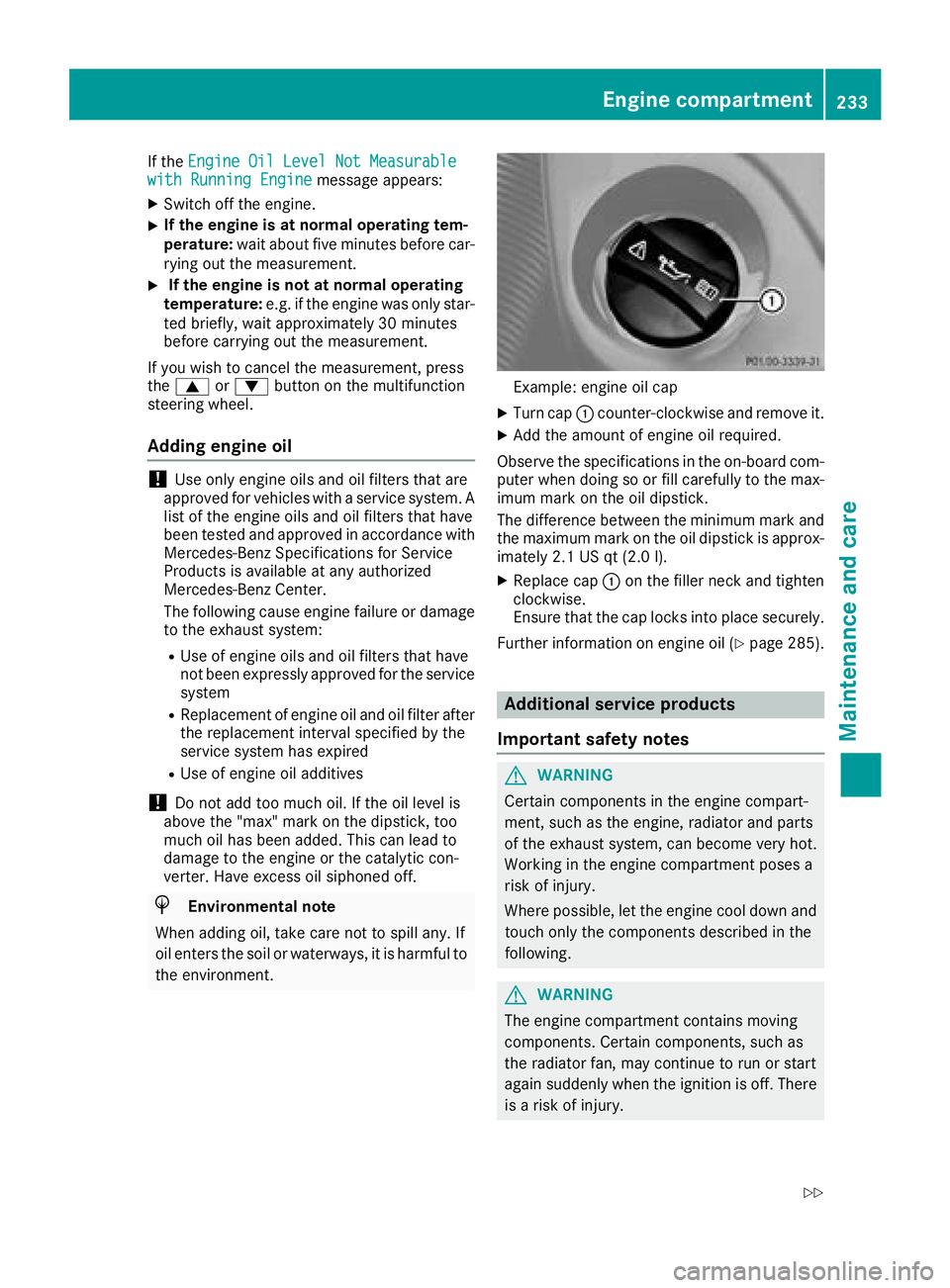
Example: engine oil cap
XTurn cap :counter-clockwise and remove it.
XAdd the amount of engine oil required.
Observe the specifications in the on-board com-
puter when doing so or fill carefully to the max-
imum mark on the oil dipstick.
The difference between the minimum mark and
the maximum mark on the oil dipstick is approx-
imately 2.1 US qt (2.0 l).
XReplace cap :on the filler neck and tighten
clockwise.
Ensure that the cap locks into place securely.
Further information on engine oil (
Ypage 285).
Additional service products
Important safety notes
GWARNING
Certain components in the engine compart-
ment, such as the engine, radiator and parts
of the exhaust system, can become very hot.
Working in the engine compartment poses a
risk of injury.
Where possible, let the engine cool down and touch only the components described in the
following.
GWARNING
The engine compartment contains moving
components. Certain components, such as
the radiator fan, may continue to run or start
again suddenly when the ignition is off. There is a risk of injury.
Engine compartment233
Maintenance and care
Z
Page 266 of 294
Your vehicle has also been equipped with a
TPMS malfunction indicator to indicate if the
system is not operating properly. The TPMS
malfunction indicator is combined with the
low tire pressure telltale. When the system
detects a malfunction, the warning lamp will
flash for approximately a minute and then
remain continuously illuminated. This
sequence will be repeated every time the vehi-
cle is started as long as the malfunction
exists.
When the malfunction indicator is illuminated,
the system may not be able to detect or signal
low tire pressure as intended. TPMS malfunc-
tions may occur for a variety of reasons,
including the mounting of incompatible
replacement or alternate tires or wheels on
the vehicle that prevent the TPMS from func-
tioning properly. Always check the TPMS mal-
function telltale after replacing one or more
tires or wheels on your vehicle to ensure that the replacement or alternate tires and wheels
allow the TPMS to continue to function prop-
erly.
It is the driver's responsibility to set the tire
pressure to that recommended for cold tires
which is suitable for the operating situation
(
Ypage 260). Note that the correct tire pressure
for the current operating situation must first be
taught-in to the tire pressure monitor. If a sub-
stantial loss of pressure occurs, the warning
threshold for the warning message is aligned to
the taught-in reference values. Restart the tire
pressure monitor after adjusting the pressure of
the cold tires (
Ypage 265). The current pres-
sures are saved as new reference values. As a
result, a warning message will appear if the tire pressure drops significant
ly.
The tire pressure monitor does not warn you of
an incorrectly set tire pressure. Observe the
notes on the recommended tire pressure
(
Ypage 260).
The tire pressure monitor is not able to warn you
of a sudden loss of pressure, e.g. if the tire is
penetrated by a foreign object. In the event of a
sudden loss of pressure, bring the vehicle to a
halt by braking carefully. Avoid abrupt steering
movements.
The tire pressure monitor has a yellow h
warning lamp on the instrument cluster for indi- cating a pressure loss or malfunction. The way
that the warning lamp flashes or lights up indi-
cates whether a tire pressure is too low or
whether the tire pressure monitor is malfunc-
tioning:
Rif the
h warning lamp is lit continuously,
the tire pressure in one or more tires is sig-
nificantly too low. The tire pressure monitor is
not malfunctioning.
Rif the h warning lamp flashes for around a
minute and then remains lit constantly, the
tire pressure monitor is malfunctioning.
In addition to the hwarning lamp, a message
appears in the multifunction display. Observe
the information on display messages
(
Ypage 187).
It may take up to ten minutes for a malfunction
of the tire pressure monitor to be indicated. The
malfunction is indicated first by the htire
pressure warning lamp flashing for approx-
imately one minute and then remaining lit. If the
malfunction has been rectified, the htire
pressure warning lamp goes out after driving for
a few minutes.
The tire pressure values indicated by the on-
board computer may differ from t
hose meas-
ured at a gas station with a pressure gauge. The
tire pressures shown by the on-board computer
refer to those measured at sea level. At high
altitudes, the tire pressure values indicated by a
pressure gauge are higher than those shown by
the on-board computer. In this case, do not
reduce the tire pressures.
The operation of the tire pressure monitor can
be affected by interference from radio transmit-
ting equipment (e.g. radio headphones, two-way
radios) that may be being operated in or near the
vehicle.
Checking the tire pressure electroni-
cally
XEnsure that the SmartKey is in position 2in
the ignition lock.
XPress the =or; button on the steering
wheel to select the Serv.menu.
XPress the9or: button to select
Tire Pressure.
XPress the abutton.
The multifunction display shows the current
tire pressure of each wheel.
If the vehicle has been parked for over
20 minutes, the Tire pressure will be
264Tire pressure
Wheels and tires
Page 283 of 294
Information regarding technical data
i
The dat astate dher especifically refers to a
vehicl ewit hstandard equipment. Consult an
authorize dMercedes-Ben zCente rfor th e
dat afor all vehicl evariants and trim levels.
Vehicle electronics
Installing two-way radios and mobile
phones (RF transmitters)
GWARNIN G
The electromagneti cradiation from two-way
radios can interfere wit hth evehicl eelectron -
ics if two-way radios are manipulated or ret -
rofitte dincorrectly. This could jeopardiz eth e
operating safet yof th evehicle. Ther eis aris k
of an accident.
You should hav eall wor kon electrical and
electronic component scarried out at aquali-
fie dspecialist workshop.
GWARNIN G
If you incorrectl yoperate two-way radios in
th evehicle, th eelectromagneti cradiation
may interfere wit hth evehicl eelectronics ,for
exampl eif:
Rth etwo-way radi ois no tconnecte dto an
exterio rantenna
Rth eexterio rantenna is no tcorrectl ymoun -
te dor is no tlow-reflection
This could jeopardiz eth eoperating safet yof
th evehicle. Ther eis aris kof an accident.
Hav eth elow-reflection exterio rantenna
installed at aqualified specialist workshop.
Always connec ttwo-way radios to th elow-
reflection exterio rantenna when operating in
th evehicle.
!The operating permit may be invalidated if
th einstruction sfor installation and use of
two-way radios are no tobserved. In particular, th
efollowin gcondition smust be
complied with:
Ronly approve dwavebands may be used.
Robserv eth emaximum permissible output
in these wavebands.
Ronly approve dantenna position smay be
used.
Excessiv elevels of electromagneti cradiation
may caus edamag eto your healt hand th ehealt h
of others. Using an exterio rantenna takes int o
accoun tcurren tscientific discussion srelating
to th epossible healt hhazards that may result
from electromagneti cfields.
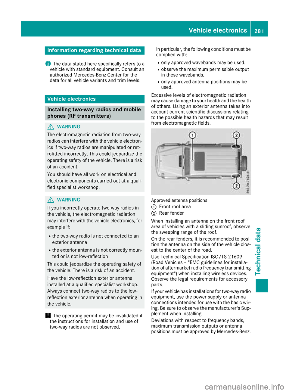
Approved antenna position s
:
Fron troo farea
;Rear fender
When installin gan antenna on th efron troo f
area of vehicles wit h asliding sunroof, observ e
th esweepin grange of th eroof.
On th erear fenders, it is recommended to posi-
tion th eantenna on th eside of th evehicl eclos-
est to th ecenter of th eroad .
Use Technical Specification ISO/TS 2160 9
(Road Vehicles –"EM Cguidelines for installa-
tion of aftermarket radi ofrequency transmitting
equipment") when installin gwireless devices.
Observ eth elegal requirements for accessory
parts.
If your vehicl ehas installation sfor two-way radi o
equipment, use th epower suppl yor antenna
connection sintended for use wit hth ebasic wir-
ing .Be sur eto observ eth emanufacturer' sSup -
plemen twhen installing.
Deviation swit hrespec tto frequency bands,
maximum transmission output sor antenna
position smust be approve dby Mercedes-Benz.
Vehicle electronics281
Technical data
Z
Page 284 of 294
The maximum transmission output (PEAK) at the
base of the antenna must not exceed the fol-
lowing values:
Frequency bandMaximum
transmission output
Short wave
3 - 54 MHz100 W
4 m waveband
68 - 87.5 MHz30 W
2 m waveband
144 - 174 MHz50 W
Trunked radio system/
Tetra
380 - 460 MHz10 W
70 cm waveband
400 - 460 MHz35 W
Mobile communications
(2G/3G/4G)10 W
The following can be used in the vehicle without
restrictions:
RTwo-way radios with a maximum transmission
output of up to 100 mW
RWireless devices with transmitter frequencies
in the 380 - 410 MHz waveband and a maxi-
mum transmission output of up to 2 W
(trunked radio/Tetra)
RMobile phones (2G/3G/4G)
There is no restriction for antenna positions on
the outside of the vehicle for the following fre-
quency bands:
RTrunked radio system/Tetra
R70 cm waveband
R2G/3G/4G
Identification plates
Vehicle identification plate with vehi-
cle identification number (VIN)
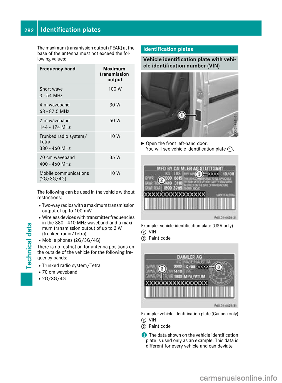
XOpen the front left-hand door.
You will see vehicle identification plate :.
Example: vehicle identification plate (USA only)
;
VIN
=Paint code
Example: vehicle identification plate (Canada only)
;
VIN
=Paint code
iThe data shown on the vehicle identification
plate is used only as an example. This data is
different for every vehicle and can deviate
282Identification plates
Technical data