2018 MERCEDES-BENZ E-CLASS WAGON dimensions
[x] Cancel search: dimensionsPage 200 of 506

WhenParking Assist PARKTRONI Cis operational
and no objec tis de tected, the segments of the
wa rning display are shown in gray .
% Ifth e entire sy stem fails, the segments of
th ewa rning display are shown in red. The
indicator lamp on thePA RKTRONI Cbut ton
lights up and theé symbol appears in
th e multifunction displa y.
If th e sy stem fails at there ar:
RThe rear segments are shown in red
when backing up.
RThe rear segments are hidden when driv‐
ing forw ards.
If Pa rking Assist PARKTRONI Cis deacti vated,
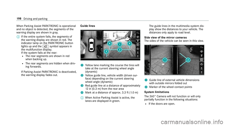
th ewa rning display fades out. Guide lines1Ye
llow lane marking the course the tires will
ta ke atthe cur rent steering wheel angle
(dynamic)
2Ye llow guide line, vehicle width (driven sur‐
fa ce) depending on the cur rent steering
wheel angle (dynamic)
3Re d guide line at a dis tance of appr oximately
12 in (0.3 m) from there ar area
4Mark at a dis tance of appr ox. 3.3 ft(1.0 m)
% When Active Parking Assist is active, the
lanes are displa yed in green. The guide lines in
the multimedia sy stem dis‐
play show the dis tances toyour vehicle. The
dis tances only apply toroad le vel.
Side view of the mir ror cameras
The sides of theve hicle can be seen in this vie w.
1Guide line of extern al vehicle dimensions
with outside mir rors folded out
2Mar ker of the wheel conta ct points
Sy stem limitations
The 360° Camera will not function or will only
partially function in thefo llowing situations:
RIf th e doors are open.
19 8
Driving and pa rking
Page 382 of 506

Changing a wheel
Notes on selecting, mounting and replacing
tires
Mercedes -AMG vehicles: be sure toobser ve
th e no tes in the Supplement. Otherwise, you
may not recognize dangers.
Yo u can ask for information rega rding permitte d
wheel/tire combinations at an authorized
Mercedes-Benz Center.
& WARNING Risk of accident due toincor‐
re ct dimensions of wheels and tires
If wheels and tires of the wrong size are
ins talled, the wheel brakes or wheel suspen‐
sion components may be damaged.
#Alw aysre place wheels and tires with
th ose that fulfill the specifications of
th e original part.
When replacing wheels, make sure tofit th e
cor rect:
RDesignation
RModel
When replacing tires, make sure toins tallth e
cor rect:
RDesignation
RManufactu rer
RModel
&
WARNING Risk of injury thro ugh exceed‐
ing the specified tire load rating or the
permissible speed rating
Exceeding the specified tire load rating or
th e permissible speed rating may lead totire
damage andtothe tires bur sting.
#Therefore, only use tire types and sizes
appr ovedfo ryo ur vehicle model.
#Obser vethe tire load rating and speed
ra ting requ ired foryo ur vehicle.
* NO
TEDama getovehicle and tires due to
non-app rove d tire types and sizes
Fo r saf etyre asons, only use wheels, tires
and accessories which havebeen appr oved
fo ryo ur vehicle byMercedes-Benz.
These tires ha vebeen specially adap tedfo r
use with the control sy stems, e.g. ABS or
ESP
®, and are mar ked as follo ws :
RMO = Mercedes-Benz Original
RMOE = Mercedes-Benz Original Extended
(run-flat tires only for cer tain wheels)
RMO1 = Mercedes-Benz Original (only cer‐
tain AMG tires)
Cer tain characteristics, e.g. handling, vehicle
noise emissions or fuel consum ption, may
ot herwise be adversely af fected. In addition,
when driving wi tha load, tire dimension var‐
iations could cause the tires tocome into
contact wi th the body and axle components.
This could result in damage tothe tires or the
ve hicle.
380
Wheels and tires
Page 384 of 506

Observethefo llowing when selecting, ins talling
and replacing tires:
ROnly use tires and wheels of the same type
(summer tires, winter tires, MOEx tended
tires) and the same make.
ROnly mount wheels of the same size on one
axle (left and right).
It is only permissible tomount a dif fere nt
wheel size in theeve nt of a flat tire in order
to drive tothe specialist workshop.
ROnly mount tires of the cor rect size onto the
wheels.
RVe hicles with a tire pressure monitoring
sy stem: All mounte d wheels must be equip‐
ped with functioning sensors forth e tire
pressure monitoring sy stem.
RAt temp eratures below 45 °F (7 °C), use win‐
te r tires or all-season tires mar ked M+S for
all wheels.
Wi nter tires bearing thei snowflake sym‐
bol in addition tothe M+S marking pr ovide
th e best possible grip in wintry road condi‐
tions.
RFo r M+S tires, only use tires with the same
tread.
RObser vethe maximum permissible speed for
th e M+S tires mounted.
If th is is below theve hicle's maximum speed,
th is must be indicated in an appropriate label
in the driver's field of vision.
RBreak in new tires at moderate speeds for
th efirs t 60 miles (100 km).
RRe place the tires af ter six years at the latest,
re ga rdless of wear.
RWhen replacing with tires that do n otfea‐
ture run-flat characteristics: Vehicles with
MOExtended tires are not equipped with a
TIREFIT kit at thefa ctor y.Equip theve hicle
with a TIREFIT kit af terre placing with tires
th at do not feature run-flat characteristics,
e.g. winter tires.
Fo r more information on wheels and tires, con‐
ta ct a qualified specialist workshop.
Be sure toalso observ eth efo llowing fur ther
re lated subjects:
RNo tes on tire pressure (→page 361)
RTire and Loading Info rmation placard
(→page 367)
RTi re size designation, load-beari ng capacity,
speed rating and load ind ex(→page 375)
RTire pressure table (→page 363)
Note s on inter changing wheels
&
WARNING Risk of injury thro ugh dif fer‐
ent wheel sizes
Inter changing the front and rear wheels if the
wheels or tires ha vediffere nt dimensions
may se verely impair the driving characteris‐
tics.
The wheel brakes or wheel suspension com‐
ponents may also be damaged.
#Ro tate front and rear wheels only ifth e
wheels and tires are of the same dimen‐
sions.
382 Wheels and tires
Page 402 of 506

Warning symbols 1advise you about:
Rpossible dangers
Rhaving service workcar ried out at a qualified
specialist workshop
Re frigerant filling capacity
Fi lling capacity forre frigerant and PAG oil
Model Refrigerant
All models2 2.2 ± 0.4 oz
(630 ± 10g)
Model PAG oil
All models2 .8 ± 0.4 oz
(80 ± 10g)
Vehicle data
Vehicle dimensions
The heights specifi ed mayvary as a result of the:
RTire s
RLoad
RCondition of the suspension
ROptional equipment
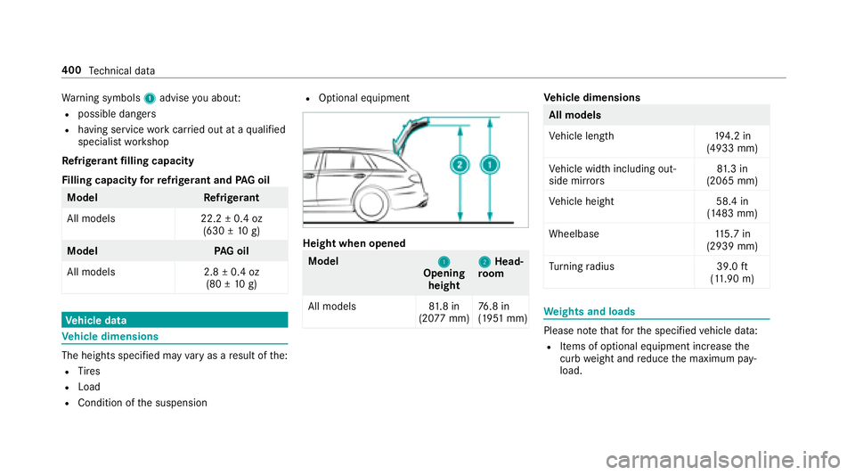
Height when opened
Model
1Opening
height 2Head‐
ro om
All models 81.8 in
(20 77mm) 76
.8 in
(1951 mm)
Ve hicle dimensions
All models
Vehicle lengt h1 94.2 in
(4933 mm)
Ve hicle width including out‐
side mir rors 81
.3 in
(2065 mm)
Ve hicle height 58.4 in
(1483 mm)
Wheelbase 115.7 in
(2939 mm)
Tu rning radius 39.0ft
(1 1. 90 m)
We ights and loads
Please no tethat forth e specified vehicle data:
RItems of optional equipment increase the
curb weight and reduce the maximum pay‐
load.
400 Tech nical da ta
Page 498 of 506

Steering wheel gearshift paddles ..........153
Ste ering wheel heater
Ac tivating/deactivating ......................... 99
St ow age areas
see Laden
see Stow age compartment
St ow age co mpartment ........................... 103
Armrest ............................................... 103
Cente r console ....................................1 03
Door .................................................... 103
Eyeglasses box .................................... 103
Glo vebox ............................................ .103
Re ar armrest ...................................... .103
St ow age co mpartments
see Laden
see Stow age compartment
St ow age space underneath the cargo
compa rtment floor .................................. 114
Sulfur content ......................................... 395
Sun visor Operating ............................................ 135
Sur round lighting
Setting .................................................1 27Sur
round View
see 360° camera
Suspension Damping characteristics ...................... 187
DY NA MIC BODY CONTROL .................. 187
Setting the suspension le vel ................ 189
Suspension see AIR BODY CONTROL
Suspension le vel
Setting ................................................. 189
Switch-off delay time Interior .................................................1 29
Switching the sur round sound on/off
Burmes te
r
®sur round sound sy stem ... 325
Synchronization function Activating/deactivating (control
panel) .................................................. 138
Ac tivating/deactivating (multimedia
sy stem) ................................................ 139
Sy stem settings
Language ............................................ .252
No tes on language selection ............... 252
Re set function (multimedia sy stem) ... .257 Setting
the dis tance unit ..................... 252
Software upda te.................................. 256
Sy stem settings
see Multimedia sy stem
T
Ta ilgate ...................................................... .64
Closing .................................................. 66
Emer gency release from the inside ...... .70
HANDS-FREE ACCESS .......................... .68
Limiting the opening angle .................... 69
Opening ................................................ .64
Opening dimensions ............................4 00
Unlocking (emergency key) .................. .69
Ta ilgate
see Locking/unlocking
Ta ilpipes (Care) ........................................ 336
Ta nk capacity
Fu el ..................................................... 396
Re ser ve(fuel) ...................................... 396
Te ch nical data
Information .......................................... 390
Ti re pressure monitoring sy stem ......... 367
Ve hicle identification plate .................. 392
496
Index
Page 502 of 506

Trip distance
see Dis tance recorder
see Trip me ter
Tr ip me ter ................................................ 220
Tr unk lid
see Tailgate
Tu rn signal indicator
see Turn signal light
Tu rn signal light ....................................... 124
Ac tivating/deactivating .......................1 24
Tw o-w ayradios
Fr equencies ......................................... 391
No tes on ins tallation .......................... .390
Tr ansmission output (maximum) .......... 391
U
Un its of measurement
Setting ................................................ .252
Un locking setting ...................................... 57
USB devices Connecting .......................................... 308
USB port .................................................. .120 User profile
.............................................. 254
Creating .............................................. 254
Importing/exporting ........................... 255
Options ................................................ 255
Selecting ............................................. 254
Using thete lephone
see Calls
V
Ve hicle .............................................. 144, 145
Ac tivating/deactivating standby
mode .................................................. .165
Cor rect use ........................................... 25
Data acquisition .............................. 26, 28
Diagnostics connection ......................... 24
Equipment ............................................. 20
Limited Warranty .................................. .26
Locking (auto matically) ......................... 63
Locking (from inside) ............................. 61
Locking (KEYLESS-GO) ........................... 61
Locking (mechanical key) ...................... 63
Lo we ring ............................................. 388
Maintenance .......................................... 21
Pa rking ................................................ 165
Problem notification .............................. 25 QR code
rescue card ............................. 26
Qualifi ed specialist workshop ................2 5
Ra ising ................................................ 385
St arting (eme rgency operation
mode) .................................................. 145
St arting (smartphone) ........................ .145
St arting (s tart/s top button) ................ 144
Switching off (s tart/s top button) ........ .157
Un locking (from inside) ........................ ..
61
Un lock
ing (KEYLESS-GO) ...................... .61
Ve ntilating (co nvenience opening) ......... 72
Vo ice commands (Voice Cont rol Sys‐
te m) ..................................................... 237
Ve hicle data
Display ing (DYNAMIC SELECT) ............ .151
Ro of load ............................................. 400
Tu rning radius ...................................... 400
Ve hicle height ...................................... 400
Ve hicle length ...................................... 400
Ve hicle width ....................................... 400
Wheelbase ...........................................4 00
Ve hicle data storage
Electronic control units ........................ .26
Ve hicle dimensions ................................. 400
500
Index