2018 MERCEDES-BENZ AMG GT COUPE instrument cluster
[x] Cancel search: instrument clusterPage 203 of 294
Warning/
indicator
lampNSignal type
Possible causes/consequences and M
Solutions
XMake sure that the air supply to the engine radiator is not blocked, e.g. by snow,
slush or ice.
XAt coolant temperatures below 248 ‡ (120 †), drive to the nearest qualified
specialist workshop.
XAvoid subjecting the engine to heavy loads, e.g. driving in mountainous terrain,
and stop-and-go traffic.
Driving systems
Warning/
indicator
lampNSignal type
Possible causes/consequences and M
Solutions
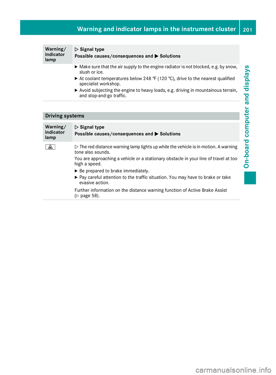
·NThe red distance warning lamp lights up while the vehicle is in motion. A warning
tone also sounds.
You are approaching a vehicle or a stationary obstacle in your line of travel at too high a speed.
XBe prepared to brake immediately.
XPay careful attention to the traffic situation. You may have to brake or take
evasive action.
Further information on the distance warning function of Active Brake Assist
(
Ypage 58).
Warning and indicator lamps in the instrument cluster201
On-board computer and displays
Z
Page 204 of 294
Tires
Warning/
indicator
lampNSignal type
Possible causes/consequences and M
Solutions
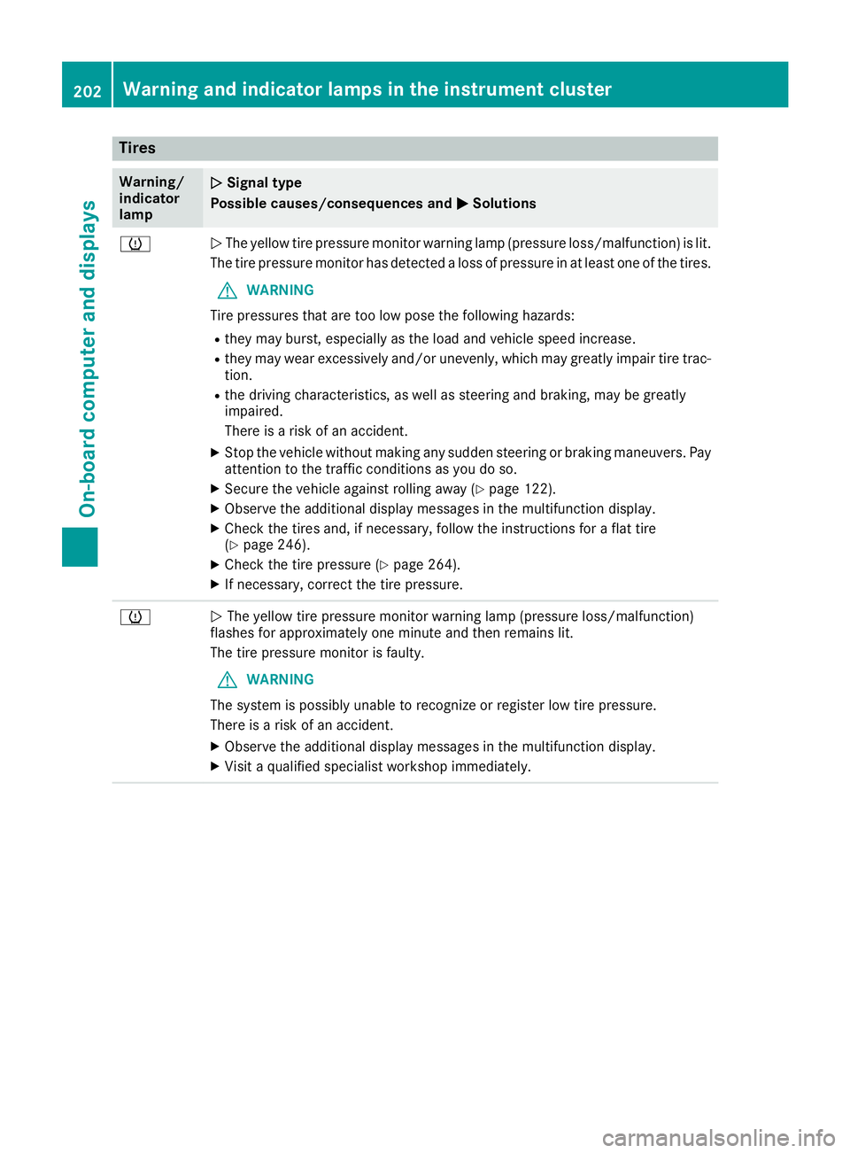
hNThe yellow tire pressure monitor warning lamp (pressure loss/malfunction) is lit.
The tire pressure monitor has detected a loss of pressure in at least one of the tires.
GWARNING
Tire pressures that are too low pose the following hazards:
Rthey may burst, especially as the load and vehicle speed increase.
Rthey may wear excessively and/or unevenly, which may greatly impair tire trac-
tion.
Rthe driving characteristics, as well as steering and braking, may be greatly
impaired.
There is a risk of an accident.
XStop the vehicle without making any sudden steering or braking maneuvers. Pay
attention to the traffic conditions as you do so.
XSecure the vehicle against rolling away (Ypage 122).
XObserve the additional display messages in the multifunction display.
XCheck the tires and, if necessary, follow the instructions for a flat tire
(Ypage 246).
XCheck the tire pressure (Ypage 264).
XIf necessary, correct the tire pressure.
hN The yellow tire pressure monitor warning lamp (pressure loss/malfunction)
flashes for approximately one minute and then remains lit.
The tire pressure monitor is faulty.
GWARNING
The system is possibly unable to recognize or register low tire pressure.
There is a risk of an accident.
XObserve the additional display messages in the multifunction display.
XVisit a qualified specialist workshop immediately.
202Warning and indicator lamps in the instrument cluster
On-board computer and displays
Page 205 of 294
Vehicle
Warning/
indicator
lampNSignal type
Possible causes/consequences and M
Solutions
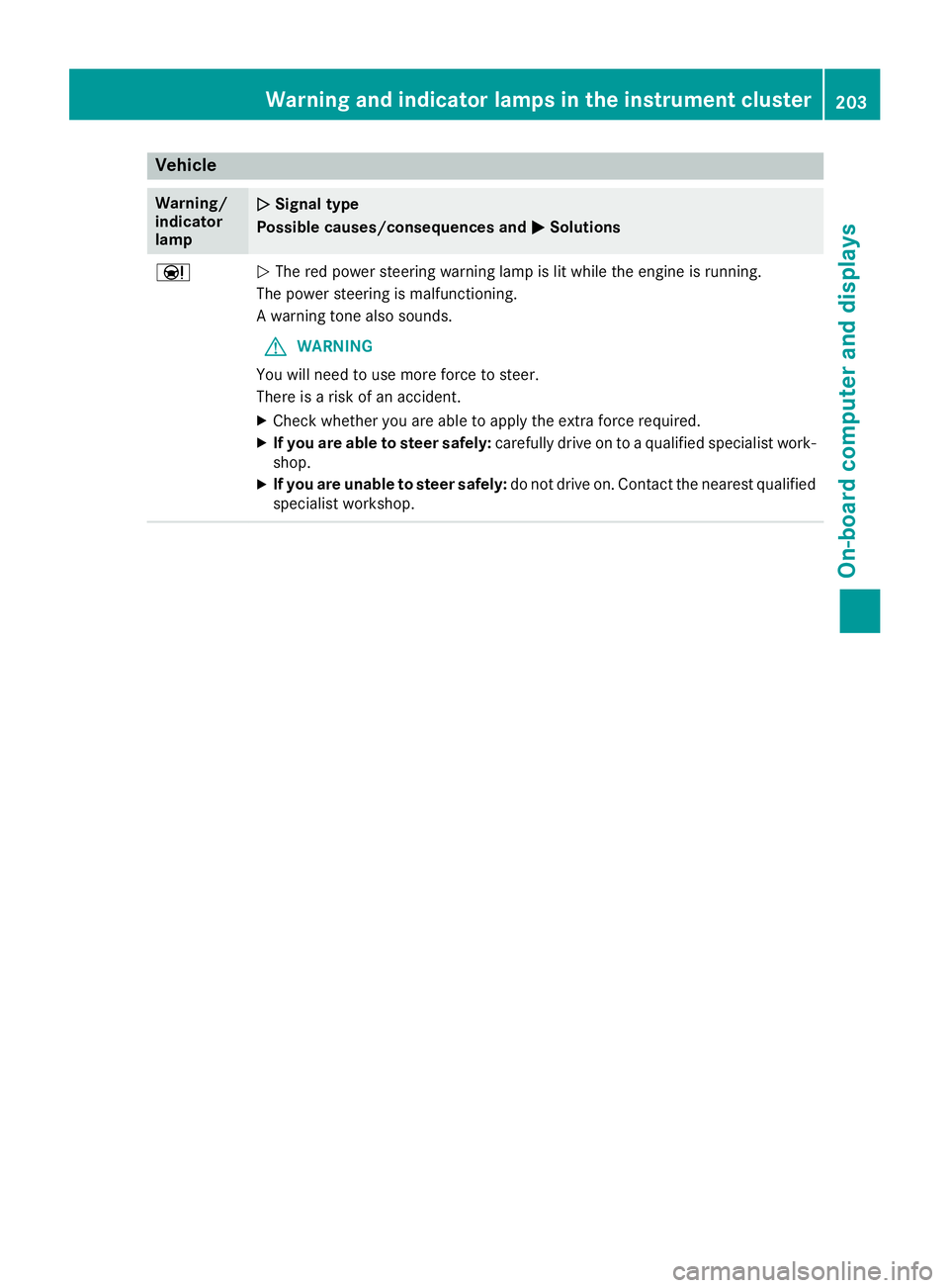
ÐNThe red power steering warning lamp is lit while the engine is running.
The power steering is malfunctioning.
A warning tone also sounds.
GWARNING
You will need to use more force to steer.
There is a risk of an accident.
XCheck whether you are able to apply the extra force required.
XIf you are able to steer safely: carefully drive on to a qualified specialist work-
shop.
XIf you are unable to steer safely: do not drive on. Contact the nearest qualified
specialist workshop.
Warning and indicator lamps in the instrument cluster203
On-board computer and displays
Z
Page 250 of 294
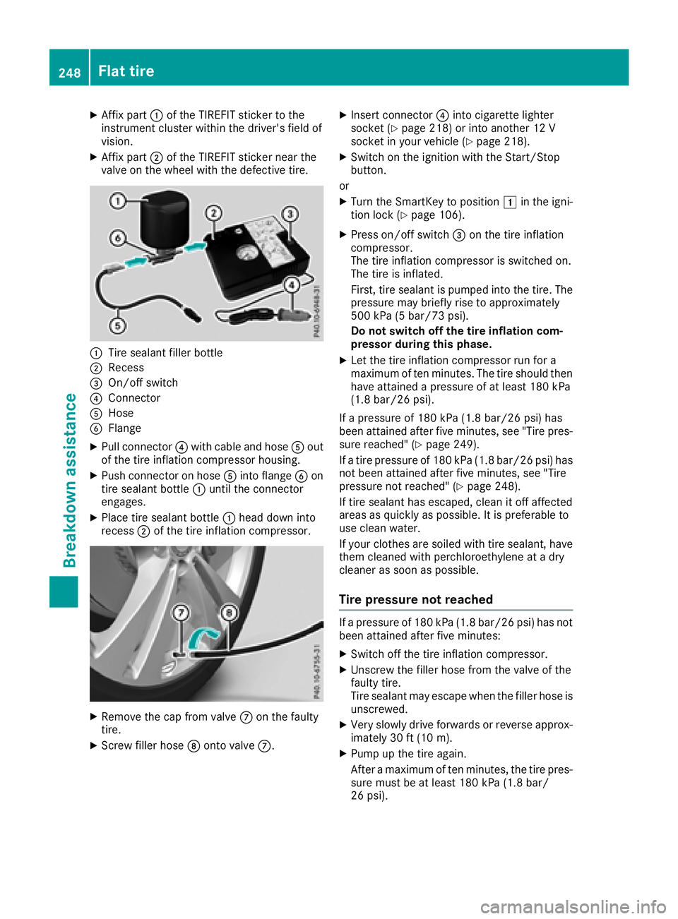
XAffix part:of the TIREFIT sticker to the
instrument cluster within the driver's field of
vision.
XAffix part ;of the TIREFIT sticker near the
valve on the wheel with the defective tire.
:Tire sealant filler bottle
;Recess
=On/off switch
?Connector
AHose
BFlange
XPull connector ?with cable and hose Aout
of the tire inflation compressor housing.
XPush connector on hose Ainto flange Bon
tire sealant bottle :until the connector
engages.
XPlace tire sealant bottle :head down into
recess ;of the tire inflation compressor.
XRemove the cap from valve Con the faulty
tire.
XScrew filler hose Donto valve C.
XInsert connector ?into cigarette lighter
socket (Ypage 218) or into another 12 V
socket in your vehicle (Ypage 218).
XSwitch on the ignition with the Start/Stop
button.
or
XTurn the SmartKey to position 1in the igni-
tion lock (Ypage 106).
XPress on/off switch =on the tire inflation
compressor.
The tire inflation compressor is switched on.
The tire is inflated.
First, tire sealant is pumped into the tire. The
pressure may briefly rise to approximately
500 kPa (5 bar/73 psi).
Do not switch off the tire inflation com-
pressor during this phase.
XLet the tire inflation compressor run for a
maximum of ten minutes. The tire should then
have attained a pressure of at least 180 kPa
(1.8 bar/26 psi).
If a pressure of 180 kPa (1.8 ba r/26 psi) has
been at tained after five minutes, see "Tire pres-
sure reached" (
Ypage 249).
If a tire pressure of 180 kPa (1.8 bar/26 psi) has
not been attained after five minutes, see "Tire
pressure not reached" (
Ypage 248).
If tire sealant has escaped, clean it off affected
areas as quickly as possible. It is preferable to
use clean water.
If your clothes ar e s
oiled with tire sealant, have
them cleaned with perchloroethylene at a dry
cleaner as soon as possible.
Tire pressure not reached
If a pressure of 180 kPa (1.8 bar/26 psi) has not
been attained after five minutes:
XSwitch off the tire inflation compressor.
XUnscrew the filler hose from the valve of the
faulty tire.
Tire sealant may escape when the filler hose is
unscrewed.
XVery slowly drive forwards or reverse approx- imately 30 ft (10 m).
XPump upthe tire again.
After a maximum of ten minutes, the tire pres-
sure must be at least 180 kPa (1.8 ba r/
26 psi) .
248Fla t tire
Breakdown assis tance
Page 251 of 294
GWARNING
If the required tire pressure is not reached
after the specified time, the tire is too badly
damaged. The tire sealant cannot repair the
tire in this instance. Damaged tires and a tire
pressure that is too low can significantly
impair the vehicle's braking and driving char-
acteristics. There is a risk of accident.
Do not continue driving. Contact a qualified
specialist workshop.
Tire pressure reached
GWARNING
A tire temporarily sealed with tire sealant
impairs the driving characteristics and is not
suitable for higher speeds. There is a risk of
accident.
You should therefore adapt your driving style
accordingly and drive carefully. Do not exceed the specified maximum speed with a tire that
has been repaired using tire sealant.
The maximum permissible speed for a tire
sealed with tire sealant is 50 mph (80 km/h).
The upper part of the TIREFIT sticker must be
affixed to the instrument cluster in the driver's
field of vision.
!Residue from the tire sealant may come out
of the filler hose after use. This could cause
stains.
Therefore, place the filler hose in the plastic
bag which contained the TIREFIT kit.
HEnvironmental note
Have the used tire sealant bottle disposed of
professionally, e.g. at a qualified specialist
workshop.
If a tire pressure of 180 kPa (1.8 bar/26 psi) has
been attained after five minutes:
XSwitch off the tire inflation compressor.
XUnscrew the filler hose from the valve of the
faulty tire.
Tire sealant may escape when the filler hose is
unscrewed.
XStow the tire sealant bottle and the tire infla-
tion compressor.
XPull away immediately.
XStop after driving for approximately ten
minutes and check the tire pressure with the
tire inflation compressor.
The tire pressure must now be at least
130 kPa (1.3 bar/19 psi).
GWARNING
If the required tire pressure is not reached
after driving for a short period, the tire is too
badly damaged. The tire sealant cannot repair
the tire in this instance. Damaged tires and a
tire pressure that is too low can significantly
impair the vehicle's braking and driving char-
acteristics. There is a risk of accident.
Do not continue driving. Contact a qualified
specialist workshop.
iIn cases such as the one mentioned above,
contact an authorized Mercedes-Benz Cen-
ter. Or call 1-800-FOR-MERCedes (in the
USA) or 1-800-387-0100 (in Canada).
XCorrect the tire pressure if it is still at least
130 kPa (1.3 bar/19 psi). See the Tire and
Loading Information placard on the driver's
side B-pillar or the tire pressure table in the
fuel filler flap for values.
XTo increase the tire pressure: switch on the
tire inflation compressor.
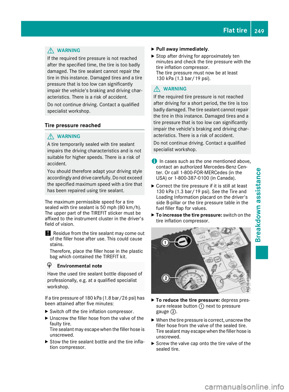
XTo reduce the tire pressure: depress pres-
sure release button :next to pressure
gauge ;.
XWhen the tire pressure is correct, unscrew the
filler hose from the valve of the sealed tire.
Tire sealant may escape when the filler hose is
unscrewed.
XScrew the valve cap onto the tire valve of the
sealed tire.
Flat tire249
Breakdown assistance
Z
Page 254 of 294
!Avoid repeated and lengthy starting attempts. Otherwise, the catalytic converter could be
damaged by the non-combusted fuel.
XDo not start the vehicle using a rapid charging device.
If your vehicle's battery is discharged, the engine can be jump-started from another vehicle or
from a donor battery using jumper cables.
The battery is not accessible in all vehicles. If the other vehicle's battery is not accessible, jump-start
the vehicle using a donor battery or a jump-starting device.
Observe the following during the jump-starting procedure:
Rthe jumper cables must not come into contact with parts that can move when the engine is
running, such as the V-belt pulley or the fan.
Rnon-insulated parts of the terminal clamps must not come into contact with other metal parts
while the jumper cables are connected to the battery and the jump-starting connection point.
Ronly use jumper cables that are not damaged and have a sufficient cross-section and insulated
terminal clamps.
Rjump-starting may be performed only using batteries with a nominal voltage of 12 V.
Ryou may only jump-start the vehicle when the engine and exhaust system are cold.
Rthe vehicles must not touch each other.
RIf the battery is fully discharged, leave the battery that is being used to jump-start connected for
a few minutes before attempting to start. This charges the battery slightly.
XSecure the vehicle by applying the electric parking brake.
XShift the transmission to position j.
XMake sure the ignition and all electrical consumers are switched off.
All indicator lamps in the instrument cluster must be off. When using the SmartKey, turn the
SmartKey to positionuin the ignition lock and remove it (
Ypage 106).
XOpen the hood.
iRight-hand-drive vehicle: the jump-starting connection points may be located on the other
side of the vehicle.
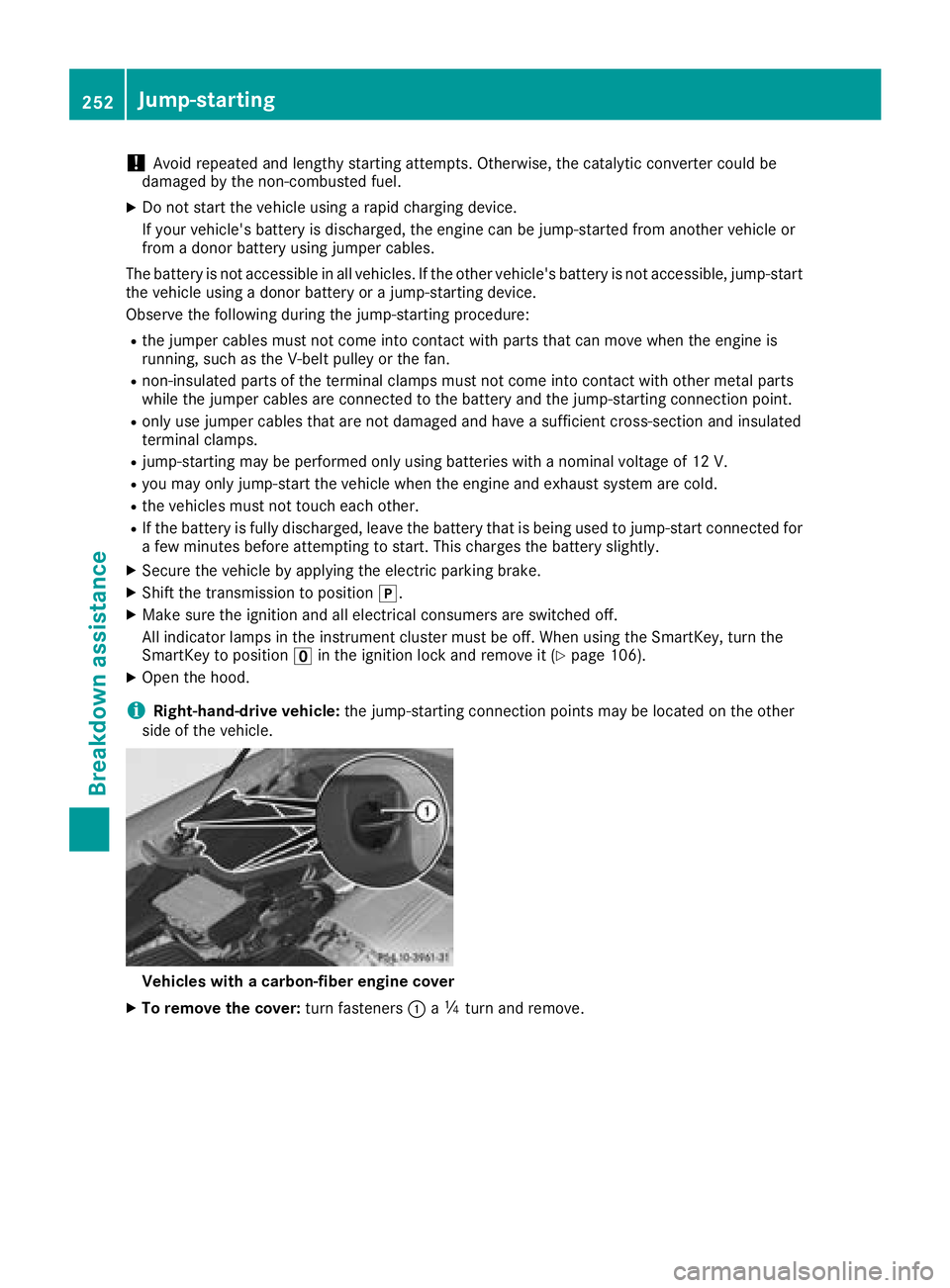
Vehicles with a carbon-fiber engine cover
XTo remove the cover: turn fasteners:aÕ turn and remove.
252Jump-starting
Breakdown assistance
Page 257 of 294
Also observe the following notes:
RIf the engine does not start, try jump-starting
it (Ypage 251). Tow-starting the vehicle is not
permitted.
RIf it is not possible to jump-start the vehicle,
have it transported to the nearest qualified
specialist workshop, e.g. an authorized
Mercedes-Benz Center.
If the vehicle can no longer be driven because of
an accident or breakdown, you have the follow-
ing options:
Rtransporting the vehicle
As a rule, you should have the vehicle trans-
ported.
Rtowing the vehicle with a tow rope or tow bar
Only tow the vehicle in exceptional cases. The
engine must be running if you tow the vehicle
with a tow rope or tow bar.
If the vehicle has suffered transmission damage,
have it transported on a transporter or trailer.
Observe the display messages in the instrument
cluster.
The battery must be connected and charged.
Otherwise, you:
Rwill not be able to switch on the ignition with
the Start/Stop button
Rcannot start the engine
Rcannot release the electric parking brake
Rcannot shift the automatic transmission to
position i
Disarm the automatic locking feature before the
vehicle is towed (
Ypage 72). You could other-
wise be locked out when pushing or towing the
ve
hicle.
Installing/removing the towing eye
Installing the towing eye
The bracket for the screw-in towing eye is
behind the radiator trim.
XRemove the towing eye from the vehicle tool
kit (Ypage 245).
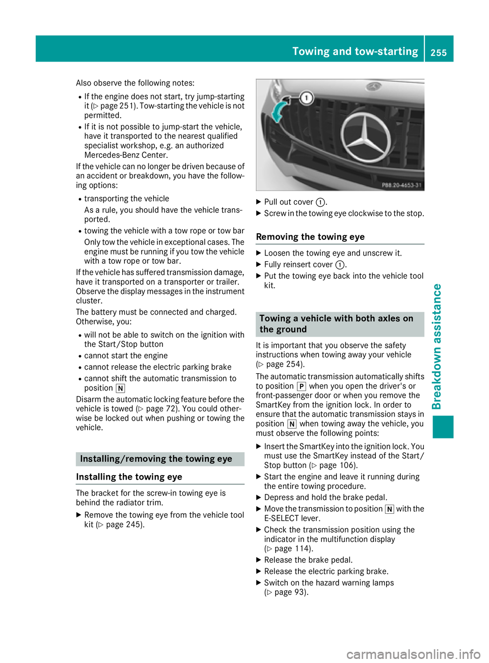
XPull out cover :.
XScrew in the towing eye clockwise to the stop.
Removing the towing eye
XLoosen the towing eye and unscrew it.
XFully reinsert cover :.
XPut the towing eye back into the vehicle tool
kit.
Towing a vehicle with both axles on
the ground
It is important that you observe the safety
instructions when towing away your vehicle
(
Ypage 254).
The automatic transmission automatically shifts
to position jwhen you open the driver's or
front-passenger door or when you remove the
SmartKey from the ignition lock. In order to
ensure that the automatic transmission stays in
position iwhen towing away the vehicle, you
must observe the following points:
XInsert the SmartKey into the ignition lock. You
must use the SmartKey instead of the Start/
Stop button (
Ypage 106).
XStart the engine and leave it running during
the entire towing procedure.
XDepress and hold the brake pedal.
XMove the transmission to position iwith the
E-SELECT lever.
XCheck the transmission position using the
indicator in the multifunction display
(
Ypage 114).
XRelease the brake pedal.
XRelease the electric parking brake.
XSwitch on the hazard warning lamps
(Ypage 93).
Towing and tow-starting255
Breakdo wn assis tance
Z
Page 259 of 294
The fuses in your vehicle serve to close down
faulty circuits. If a fuse blows, all the compo-
nents on the circuit and their functions stop
operating.
Before changing a fuse
XSwitch off the engine.
XSwitch off all electrical consumers.
XOpen the driver's door.
The on-board electronics are now in key posi-
tionu. This is the same as the key having
been removed.
or, if the SmartKey is inserted in the ignition
lock:
XRemove the SmartKey from the ignition lock.
XSecure the vehicle against rolling away
(Ypage 122).
All indicator lamps in the instrument cluster
must be off.
Fuse box in the front-passenger foot-
well
!
The floor panel must be installed properly,
otherwise moisture or dirt could impair the
function of the fuses.
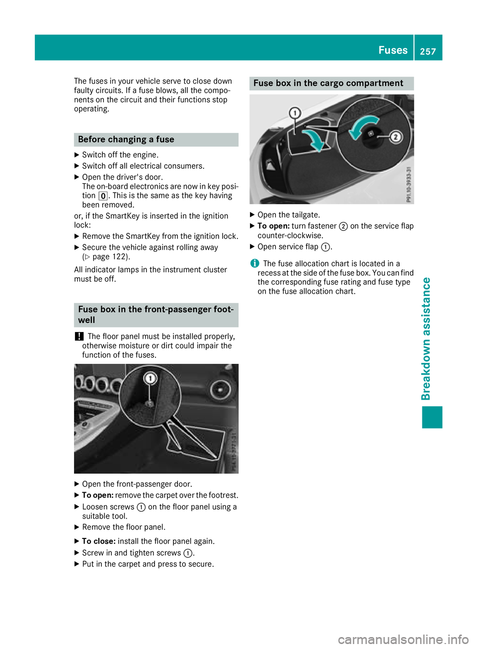
XOpen the front-passenger door.
XTo open: remove the carpet over the footrest.
XLoosen screws :on the floor panel using a
suitable tool.
XRemove the floor panel.
XTo close: install the floor panel again.
XScrew in and tighten screws :.
XPut in the carpet and press to secure.
Fuse box in the cargo compartment
XOpen the tailgate.
XTo open:turn fastener ;on the service flap
counter-clockwise.
XOpen service flap :.
iThe fuse allocation chart is located in a
recess at the side of the fuse box. You can find
the corresponding fuse rating and fuse type
on the fuse allocation chart.
Fuses257
Breakdown assistance
Z