2018 MERCEDES-BENZ AMG GT COUPE phone
[x] Cancel search: phonePage 226 of 294

The vehicle can be immediately remotely locked
within four days of the ignition being turned off.
After this time, remote closing may be delayed
by 15 to 60 minutes. After 30 days the vehicle
can no longer be locked remotely.
The vehicle remote closing feature is available if
the relevant mobile phone network is available
and a data connection is possible.
XContact the following service hotlines:
Mercedes-Benz Customer Assistance Center
at 1-800 FOR-MERCEDES (1-800-367-6372)
or 1-866-990-9007
You will be asked for your password.
The next time you are inside the vehicle and you
switch on the ignition, the Doors Locked
Remotelymessage appears in the multifunction
display.
Alternatively, the vehicle can be locked via:
Rthe Internet, under the "Owners Online" sec-
tion
Rtelephone applications (e.g. for iPhone®,
Android™)
To do this, you will need your identification num-
ber and password.
Stolen vehicle recovery service
If your vehicle has been stolen:
XNotify the police.
The police will issue a numbered incident
report.
XForward this number to the Mercedes-Benz
Customer Assistance Center along with your
PIN.
The Mercedes-Benz Customer Assistance
Center then tries to locate the system. The
Mercedes-Benz Customer Assistance Center
contacts you and the local law enforcement
agency if the vehicle is located.
However, only the law enforcement agency is
informed of the location of the vehicle.
If the anti-theft alarm system is activated for
longer than 30 seconds, mbrace automatically
notifies the Mercedes-Benz Customer Assis-
tance Center.
Vehicle Health Check
With the Vehicle Health Check, the Customer
Assistance Center can provide improved sup-
port for problems with your vehicle. During an existing call, vehicle data is transferred to the
Customer Assistance Center.
The customer service representative can use
the received data to decide what kind of assis-
tance is required. You are then, for example,
guided to the nearest Mercedes-Benz Service
Center or a recovery vehicle is called.
If vehicle data need to be transferred during an
Info call or a Roadside Assistance call, this is
initiated by the Customer Assistance Center.
The
Roadside Assistance Connected
mes-
sage appears in the display. If the Vehicle Health
Check can be started, the Request
forVehi‐cle Diagnostics Received Start vehi‐cle diagnostics?message appears in the
display.
XPress the Yesbutton to confirm the message.
XIf theVehicle Diagnostics PleaseStart Ignitionmessage appears: turn the
SmartKey to key position 2in the ignition
lock (
Ypage 106).
XIf the Please follow the instructionsreceivedbyphoneandmoveyourvehi‐cle to a safe position.message
appears: please follow the instructions
received by phone and move your vehicle to a
safe position.
The message in the display disappears.
The vehicle operating state check begins.
During this procedure, you will see the Vehi‐
cle Diagnostics Activemessage.
If you select Cancel
, the Vehicle Health
Check is canceled completely.
When the check is complete, the Sending
vehicle diagnostics data. (Voice con‐nection may be interrupted duringdatatransfer)message appears. The vehicle
data can now be sent.
XPress the OKbutton to confirm the message.
The voice connection with the Customer
Assistance Center is terminated.
The Vehicle Diagnostics: Transfer‐
ring Data...message appears.
The vehicle data is sent to the Customer
Assistance Center.
Depending on what the customer service rep-
resentative agreed with you, the voice connec-
tion is re-established after the transfer is com-
plete. If necessary, you will be contacted at a
later time by another means, e.g. by e-mail or
phone.
224Features
Stowage and features
Page 231 of 294
door opener, contact a Mercedes-Benz Service
Center.
Alternatively, you can call the following tele-
phone assistance services:
RUSA:Mercedes-Benz Customer Assistance
Center at 1-800 FOR-MERCEDES
RCanada: Customer Service at
1-800-387-0100
RHomeLink®hotline 1-800-355-3515 (free of
charge)
More information on HomeLink
®and/or com-
patible products is also available online at
http://www.homelink.co m.
Notes on the declaration of conformity
(
Ypage 27).
USA: FCC ID: CB2HMIHL4
Canada: IC: 279B-HMIHL4
Important safety notes
GWARNING
When you operate or program the garage door
with the integrated garage door opener, per-
sons in the range of movement of the garage
door can become trapped or struck by the
garage door. There is a risk of injury.
When using the integrated garage door
opener, always make sure that nobody is
within the range of movement of the garage
door.
GWARNING
Combustion engines emit poisonous exhaust
gases such as carbon monoxide. Inhaling
these exhaust gases leads to poisoning. There
is a risk of fatal injury. Therefore never leave
the engine running in enclosed spaces with-
out sufficient ventilation.
Programming
Programming the buttons
Pay attention to the "Important safety notes"
(Ypage 229).
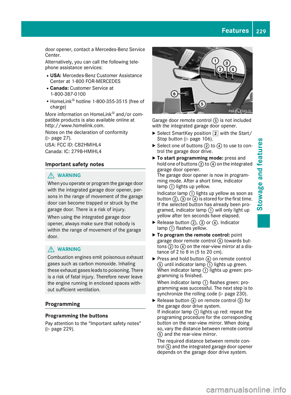
Garage door remote control Ais not included
with the integrated garage door opener.
XSelect SmartKey position 2with the Start/
Stop button (Ypage 106).
XSelect one of buttons ;to? to use to con-
trol the garage door drive.
XTo start programming mode: press and
hold one of buttons ;to? on the integrated
garage door opener.
The garage door opener is now in program-
ming mode. After a short time, indicator
lamp :lights up yellow.
Indicator lamp :lights up yellow as soon as
button ;,=or? is stored for the first time.
If the selected button has already been pro-
gramed, indicator lamp :will only light up
yellow after ten seconds have elapsed.
XRelease button ;,=or?. Indicator
lamp :flashes yellow.
XTo program the remote control: point
garage door remote control Atowards but-
tons ;to? on the rear-view mirror at a dis-
tance of 2 to 8 in (5 to 20 cm).
XPress and hold button Bon remote control
A until indicator lamp :lights up green.
When indicator lamp :lights up green: pro-
gramming is finished.
When indicator lamp :flashes green: pro-
gramming was successful. The next step is to
synchronize the rolling code (
Ypage 230).
XRelease button Bon remote control Afor
the garage door drive system.
If indicator lamp :lights up red: repeat the
programing procedure for the corresponding
button on the rear-view mirror. When doing
so, vary the distance between remote control
A and the rear-view mirror.
The required distance between remote con-
trol Aand the integrated garage door opener
depends on the garage door drive system.
Features229
Stowage and features
Z
Page 236 of 294
XPull oil dipstick:out of the dipstick guide
tube.
XWipe off oil dipstick :.
XSlowly slide oil dipstick :into the guide tube
to the stop, and take it out again.
If the level is between MIN mark =and MAX
mark ;, the oil level is correct.
XIf the oil level has dropped to MIN mark =or
below, add 1.1 US qt (1.0 liter) engine oil.
Checking the oil level using the on-board computer
Calling up the oil level measurement
XSelect key position 2with the Start/Stop button.
XUse ò on the steering wheel to call up the list of menus.
XPress the :or9 button on the steering wheel to select the Servicemenu.
XConfirm by pressingaon the steering wheel.
XUse: or9 to select the Engine Oil Levelsubmenu.
XPressato confirm the selection.
The Measuring Engine Oil Level Accurate Only When Vehicle Is Levelmessage
appears in the multifunction display.
The measurement takes a few seconds. You will see a message in the multifunction display. The
messages are explained in the following chapter.
Engine oil level display messages
Display messagesPossible causes/consequences and MSolutions
Engine Oil Level OKThe engine oil level is correct.
Check Engine OilLevel (Add 1 Liter)
The engine oil level is too low.
XAdd 1.1 US qt (1.0 liter) of engine oil.
Reduce Engine OilLevel
The engine oil level is too high.
XHave excess engine oil siphoned off.
For Engine OilLevelIgnitionMustBe On
The ignition is switched off.
XSelect key position2with the Start/Stop button.
Need More Time toCheck Engine OilLevel
The required waiting period was not observed.
XThe engine must be at regular operating temperature.
Measurements can only be taken within the first four minutes after
the engine has been switched off.
Engine Oil LevelNotMeasurablewithEngine Running
The engine is running; oil level measurement is not possible.
XSwitch off the engine.
XRepeat the measurement. Observe the required waiting period.
234Engine compartment
Maintenance and care
Page 237 of 294
Display messagesPossible causes/consequences andMSolutions
Engine Oil LevelCorrectMeasurementOnlyif Vehicl eIson Level Ground
The vehicl eis no tparked on alevel surface.
XPark th evehicl eon alevel surface.
Engine Oil LevelNot Measurabl e
Oil level measuremen twit hth eoil dipstick is possible. The measurin g
system is malfunctioning .
XVisitaqualified specialist workshop .
Adding engine oil
GWARNING
Certain component sin th eengin ecompart-
ment, suc has th eengine, radiato rand part s
of th eexhaust system, can become ver yhot .
Working in th eengin ecompartmen tposes a
ris kof injury.
Where possible, let th eengin ecool down and
touch only th ecomponent sdescribed in th e
following.
GWARNIN G
If engin eoil comes int ocontact wit hhot com-
ponents in th eengin ecompartment, it may
ignite. There is aris kof fir eand injury.
Mak esur ethat engin eoil is no tspilled next to
th efiller neck .Let th eengin ecool down and
thoroughly clean th eengin eoil off th ecom-
ponents before starting th eengine.
HEnvironmenta lnot e
Whe naddin goil, tak ecar eno tto spil lany. If
oil enters th esoil or waterways, it is harmful to
th eenvironment.
!Use only engin eoils and oil filters that are
approve dfor vehicles wit h aservic esystem. A
list of th eengin eoils and oil filters that hav e
been tested and approve din accordanc ewit h
Mercedes-Ben zSpecification sfor Service
Products is available at any authorize d
Mercedes-Ben zCenter. The followin
gcaus eengin efailure or damag e
to th eexhaust system:
RUse of engin eoils and oil filters that hav e
no tbeen expressl yapprove dfor th eservic e
system
RReplacement of engin eoil and oil filter after
th ereplacemen tinterval specified by th e
servic esystem has expired
RUse of engin eoil additive s
!Do notadd to omuc hoil. If th eoil level is
abov eth e"max "mar kon th edipstick ,to o
muc hoil has been added .This can lead to
damag eto th eengin eor th ecatalytic con-
verter. Hav eexcess oil siphoned off .
Example: engineoil cap
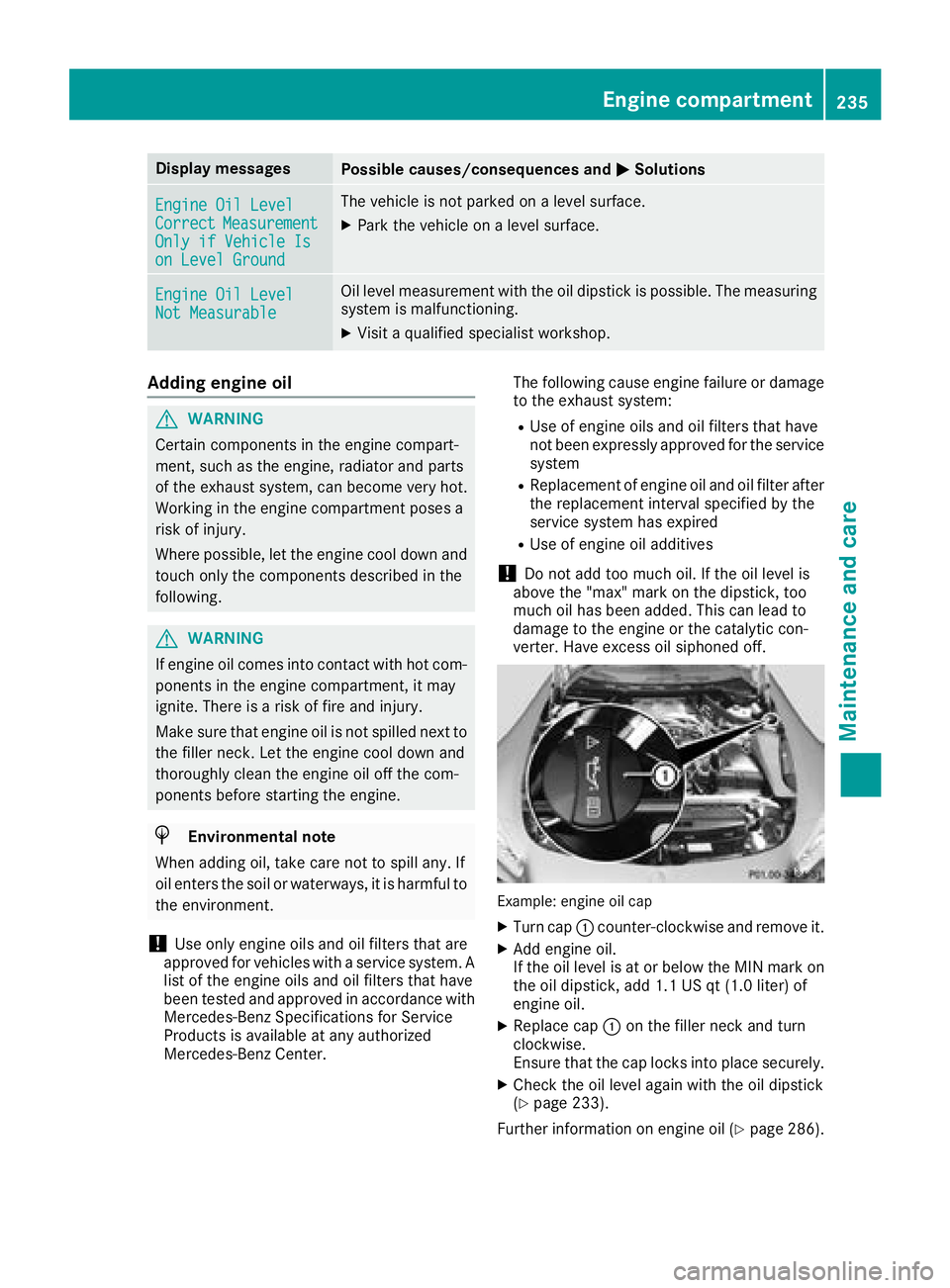
XTurn cap :counter-clockwise and remove it .
XAddengin eoil.
If th eoil level is at or belo wtheMIN mar kon
th eoil dipstick ,add 1. 1US qt (1. 0liter) of
engin eoil.
XReplac ecap :on th efiller neck and tur n
clockwise .
Ensur ethat th ecap locks int oplac esecurely.
XChec kth eoil level again wit hth eoil dipstick
(Ypage 233).
Further information on engin eoil (
Ypage 286).
Engine compartment235
Maintenance and care
Z
Page 267 of 294
ensure that the replacement or alternate Tires
and wheels allow the TPMS to continue to
function properly.
It is the driver's responsibility to set the tire
pressure to that recommended for cold tires
which is suitable for the operating situation
(
Ypage 261). Note that the correct tire pressure
for the current operating situation must first be
taught-in to the tire pressure monitor. If a sub-
stantial loss of pressure occurs, the warning
threshold for the warning message is aligned to
the taught-in reference values. Restart the tire
pressure monitor after adjusting the pressure of
the cold tires (
Ypage 266). The current pres-
sures are saved as new reference values. As a
result, a warning message will appear if the tire pressure drops significantly.
The tire pressure monitor does not warn you of
an incorrectly set tire pressure. Observe the
notes on the recommended tire pressure
(
Ypage 261).
The tire pressure monitor is not able to warn you
of a sudden loss of pressure, e.g. if the tire is
penetrated by a foreign object. In the event of a
sudden loss of pressure, bring the vehicle to a
halt by braking carefully. Avoid abrupt steering
movements.
The tire pressure monitor has a yellow warning
lamp in the instrument cluster for indicating
pressure loss or a malfunction. Whether the
warning lamp flashes or lights up indicates
whether a tire pressure is too low or the tire
pressure monitor is malfunctioning:
Rif the warning lamp is lit continuously, the tire
pressure on one or more tires is significantly
too low. The tire pressure monitor is not mal-
functioning.
Rif the warning lamp flashes for around a
minute and then remains lit constantly, the
tire pressure monitor is malfunctioning.
In addition to the warning lamp, a message
appears in the multifunction display. Observe
the information on display messages
(
Ypage 186).
It may take up to ten minutes for a malfunction
of the tire pressure monitor to be indicated. A
malfunction will be indicated by the tire pres-
sure warning lamp flashin
g for approximately
one minute and then remaining lit. When the
malfunction has been rectified, the tire pressure
warning lamp goes out after a few minutes of
driving. The tire pressure values indicated by the on-
board computer may differ from those meas-
ured at a gas station with a pressure gage. The
tire pressures shown by the on-board computer
refer to those measured at sea level. At high
altitudes, the tire pressure values indicated by a pressure gage are higher than those shown by
the on-board computer. In this case, do not
reduce the tire pressures.
The operation of the tire pressure monitor can
be affected by interference from radio transmit-
ting equipment (e.g. radio headphones, two-way
radios) that may be being operated in or near the vehicle.
Checking the tire pressure electroni-
cally
XSwitch on the ignition (Ypage 106).
XPress òon the steering wheel to call up
the list of menus.
XPress 9or: on the steering wheel to
select the Servicemenu.
XPressa.
XPress9or: to select Tire Pres‐sure.
XPressa.
The current tire pressure of each tire is shown
in the multifunction display.
If the vehicle was parked for longer than
20 minutes, the Tire pressure will be
displayed after driving a few minutesmessage appears.
After a teach-in process, the tire pressure mon-
itor automatically detects new wheels or new
sensors. As long as a clear allocation of the tire
pressure value to the individual wheels is not
possible, theTire
PressureMonitorActivemessage is shown instead of the tire pressure
display. The tire pressures are already being
monitored.
Tire pressure monitor warning mes-
sages
If the tire pressure monitor detects a pressure
loss in one or more tires, a warning message is
shown in the multifunction display. The yellow
tire pressure warning lamp then lights up.
RIf thePlease Correct Tire Pressuremessage appears in the multifunction display,
the tire pressure in at least one tire is too low.
Tire pressure265
Wheels and tires
Z
Page 284 of 294
Information regarding technical data
i
The dat astate dher especifically refers to a
vehicl ewit hstandard equipment. Consult an
authorize dMercedes-Ben zCente rfor th e
dat afor all vehicl evariants and trim levels.
Vehicle electronics
Tampering with the engine electron-
ics
!
Only hav ewor kcarried out on th eengin e
electronics and it sassociated parts, suc has
control units, sensors, actuating component s
and connecto rleads ,at aqualified specialist
workshop. Vehicl ecomponent smay other -
wise wear mor equickly and th evehicle's
operating permit may be invalidated.
Installing wireless devices and mobile
phones
GWARNIN G
The electromagneti cradiation from two-way
radios can interfere wit hth evehicl eelectron -
ics if two-way radios are manipulated or ret -
rofitte dincorrectly. This could jeopardiz eth e
operating safet yof th evehicle. Ther eis aris k
of an accident.
You should hav eall wor kon electrical and
electronic component scarried out at aquali-
fie dspecialist workshop.
GWARNIN G
If you incorrectl yoperate two-way radios in
th evehicle, th eelectromagneti cradiation
may interfere wit hth evehicl eelectronics ,for
exampl eif:
Rth etwo-way radi ois no tconnecte dto an
exterio rantenna
Rth eexterio rantenna is no tcorrectl ymoun -
te dor is no tlow-reflection
This could jeopardiz eth eoperating safet yof
th evehicle. Ther eis aris kof an accident.
Hav eth elow-reflection exterio rantenna
installed at aqualified specialist workshop.
Always connec ttwo-way radios to th elow-
reflection exterio rantenna when operating in
th evehicle.
!The operating permit may be invalidated if
th einstruction sfor installation and use of
two-way radios are no tobserved.
In particular, th efollowin gcondition smust be
complied with:
Ronly approve dwavebands may be used.
Robserv eth emaximum permissible output
in these wavebands.
Ronly approve dantenna position smay be
used.
Excessiv elevels of electromagneti cradiation
may caus edamag eto your healt hand th ehealt h
of others. Using an exterio rantenna takes int o
accoun tcurren tscientific discussion srelating
to th epossible healt hhazards that may result
from electromagneti cfields.
The followin gcan be used in th evehicl ewithout
restrictions:
Rtwo-way radios wit h amaximum transmission
output of up to 10 0mW
Rmobile phones (2G/3G/4G)
Identification plates
Vehicle identification plate with vehi-
cle identification number (VIN)
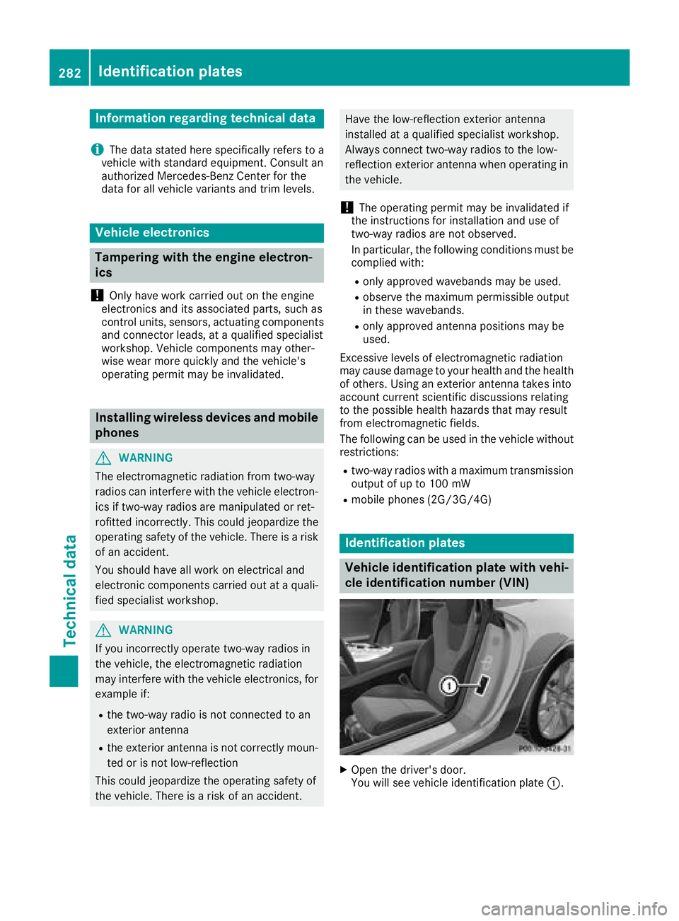
XOpen th edriver' sdoor .
You will see vehicl eidentification plat e:.
282Identification plates
Technical data