2018 Hyundai Creta display
[x] Cancel search: displayPage 271 of 472
![Hyundai Creta 2018 Owners Manual 4-57
Multimedia System
4
Setup
Setup is the screen to control Audio
system settings.
Press the [SETUP]button on the
audio system.
Display
Press the [SETUP]button on the
audio system ➟Select [Displa Hyundai Creta 2018 Owners Manual 4-57
Multimedia System
4
Setup
Setup is the screen to control Audio
system settings.
Press the [SETUP]button on the
audio system.
Display
Press the [SETUP]button on the
audio system ➟Select [Displa](/manual-img/35/14530/w960_14530-270.png)
4-57
Multimedia System
4
Setup
Setup is the screen to control Audio
system settings.
Press the [SETUP]button on the
audio system.
Display
Press the [SETUP]button on the
audio system ➟Select [Display].
Mode: Set the screen brightness to
be adjusted automatically accord-
ing to ambient lighting conditions
or set the screen to stay bright or
dark continuously.
Illumination: The brightness of the
audio screen can be changed.
Text Scroll: If text is too long to be
displayed on the screen, enable
the text scroll function.
Sound
Press the [SETUP]button on the
audio system ➟Select [Sound].
Position: Sound balance and fader
can be adjusted.
Tone: Sound tone color can be
adjusted.
Back-up Warning Priority:
- Automatically lower audio vol-
ume while reversing.
- Control the audio volume level
automatically in R-Position.
If volume level over “5 level” then
down to “5 level”.If volume level under “5 level”
then maintain the volume level.
Return the volume level when R-
Position was cancelled.
In R-Positon, if driver change the
volume level then volume
changed.
Apply the volume control option
“On/Off ” in “Setup”: Default is
“On”.
Speed Dependent Volume:
Automatically adjust volume based
on vehicle speed.
Beep: Select whether to play a
beep sound when the screen is
touched.
Page 272 of 472
![Hyundai Creta 2018 Owners Manual 4-58
Multimedia System
Bluetooth
Press the [SETUP]button on the
audio system ➟Select [Bluetooth].
Connections: Control pairing, dele-
tion, connection and disconnection
of Bluetooth
®devices.
Aut Hyundai Creta 2018 Owners Manual 4-58
Multimedia System
Bluetooth
Press the [SETUP]button on the
audio system ➟Select [Bluetooth].
Connections: Control pairing, dele-
tion, connection and disconnection
of Bluetooth
®devices.
Aut](/manual-img/35/14530/w960_14530-271.png)
4-58
Multimedia System
Bluetooth
Press the [SETUP]button on the
audio system ➟Select [Bluetooth].
Connections: Control pairing, dele-
tion, connection and disconnection
of Bluetooth
®devices.
Auto Connection Priority: Set the
connection priority of Bluetooth
®
devices when the vehicle is start-
ed.
Download Contacts: Contacts can
be downloaded from connected
Bluetooth
®devices.
Information
• When paired devices are deleted,
the call history and contacts of the
device saved to the audio system are
deleted.
• For Bluetooth
®connections with
low connection priority, some time
may be required for the connection
to be established.
• Contacts can be downloaded only
from the currently connected
Bluetooth
®device.
• If no Bluetooth
®device is connected,
the Download Contacts button is
disabled.
System
Press the [SETUP]button on the
audio system ➟Select [System].
Language: Change the user lan-
guage.
Default: Reset the audio system.
Information
• The system resets to the default val-
ues, and all saved data and settings
are lost.
Display Off
To prevent glare, the screen can be
turned off with the audio system in
operation.
Press the [SETUP]button on the
audio system ➟Select [Display Off].
i
i
Page 278 of 472

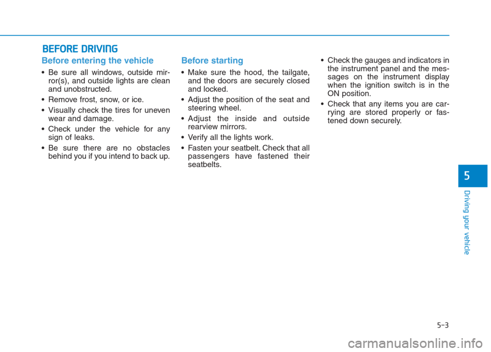
Before entering the vehicle
• Be sure all windows, outside mir-
ror(s), and outside lights are clean
and unobstructed.
Remove frost, snow, or ice.
Visually check the tires for uneven
wear and damage.
Check under the vehicle for any
sign of leaks.
Be sure there are no obstacles
behind you if you intend to back up.
Before starting
Make sure the hood, the tailgate,
and the doors are securely closed
and locked.
Adjust the position of the seat and
steering wheel.
Adjust the inside and outside
rearview mirrors.
Verify all the lights work.
Fasten your seatbelt. Check that all
passengers have fastened their
seatbelts. Check the gauges and indicators in
the instrument panel and the mes-
sages on the instrument display
when the ignition switch is in the
ON position.
Check that any items you are car-
rying are stored properly or fas-
tened down securely.
B BE
EF
FO
OR
RE
E
D
DR
RI
IV
VI
IN
NG
G
5-3
Driving your vehicle
5
Page 299 of 472

5-24
Driving your vehicle
Automatic transaxle operation
The automatic transaxle has six for-
ward speeds and one reverse speed.
The individual speeds are selected
automatically in the D (Drive) posi-
tion.The indicator in the instrument clus-
ter displays the shift lever position
when the ignition switch is in the ON
position.
P (Park)
Always come to a complete stop
before shifting into P (Park).
To shift from P (Park), you must
depress firmly on the brake pedal
and make sure your foot is off the
accelerator pedal.
If you have done all of the above and
still cannot shift the lever out of P
(Park), see “Shift-Lock Release” on
page 5-27.
The shift lever must be in P (Park)
before turning the engine off. To reduce the risk of serious
injury or death:
ALWAYS check the surround-
ing areas near your vehicle for
people, especially children,
before shifting a vehicle into
D (Drive) or R (Reverse).
Before leaving the driver’s
seat, always make sure the
shift lever is in the P (Park)
position, then set the parking
brake, and place the ignition
switch in the LOCK/OFF posi-
tion. Unexpected and sudden
vehicle movement can occur
if these precautions are not
followed.
Do not use engine braking
(shifting from a high gear to
lower gear) rapidly on slip-
pery roads. The vehicle may
slip causing an accident.
WARNING
Page 314 of 472

The ESC OFF indicator light comes
on when the ESC is turned off with
the button.
Driving with wheels and tires with
different sizes may cause the ESC
system to malfunction. Before
replacing tires, make sure all four
tires and wheels are the same
size. Never drive the vehicle with
different sized tires and wheels
installed.ESC OFF usage
When Driving
The ESC OFF mode should only be
used briefly to help free the vehicle if
stuck in snow or mud by temporarily
stopping operation of the ESC to
maintain wheel torque.
To turn ESC off while driving, press
the ESC OFF button while driving on
a flat road surface.To prevent damage to the
transaxle:
Do not allow wheel(s) of one
axle to spin excessively while
the ESC, ABS, and parking brake
warning lights are displayed.
The repairs would not be cov-
ered by the vehicle warranty.
Reduce engine power and do
not spin the wheel(s) excessive-
ly while these lights are dis-
played.
When operating the vehicle on a
dynamometer, make sure the
ESC is turned off (ESC OFF light
illuminated).
Information
Turning the ESC off does not affect
ABS or standard brake system opera-
tion.
i
NOTICE
NOTICE
5-39
Driving your vehicle
5
When the ESC is blinking, this
indicates the ESC is active:
Drive slowly and NEVER
attempt to accelerate. NEVER
turn the ESC off while the ESC
indicator light is blinking or you
may lose control of the vehicle
resulting in an accident.
WARNING
Page 415 of 472

7-58
Maintenance
Wheel size designation
Wheels are also marked with impor-
tant information that you need if you
ever have to replace one. The follow-
ing explains what the letters and
numbers in the wheel size designa-
tion mean.
Example wheel size designation:
6.0JX16
6.0 - Rim width in inches.
J - Rim contour designation.
16 - Rim diameter in inches.
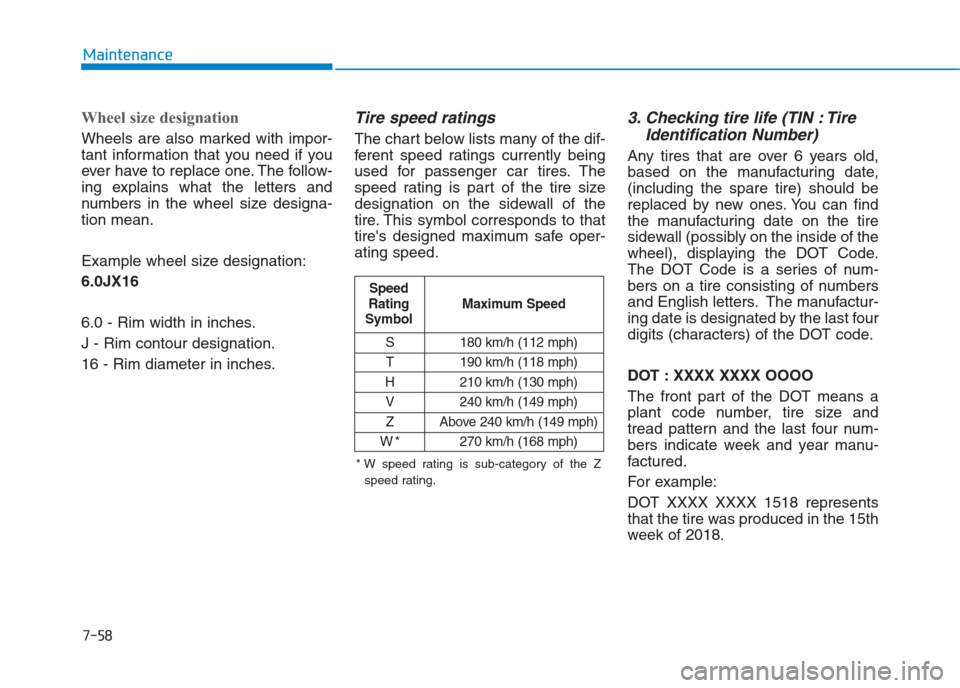
Tire speed ratings
The chart below lists many of the dif-
ferent speed ratings currently being
used for passenger car tires. The
speed rating is part of the tire size
designation on the sidewall of the
tire. This symbol corresponds to that
tire's designed maximum safe oper-
ating speed.
3. Checking tire life (TIN : Tire
Identification Number)
Any tires that are over 6 years old,
based on the manufacturing date,
(including the spare tire) should be
replaced by new ones. You can find
the manufacturing date on the tire
sidewall (possibly on the inside of the
wheel), displaying the DOT Code.
The DOT Code is a series of num-
bers on a tire consisting of numbers
and English letters. The manufactur-
ing date is designated by the last four
digits (characters) of the DOT code.
DOT : XXXX XXXX OOOO
The front part of the DOT means a
plant code number, tire size and
tread pattern and the last four num-
bers indicate week and year manu-
factured.
For example:
DOT XXXX XXXX 1518 represents
that the tire was produced in the 15th
week of 2018.
S 180 km/h (112 mph)
T 190 km/h (118 mph)
H 210 km/h (130 mph)
V 240 km/h (149 mph)
Z Above 240 km/h (149 mph)
W*270 km/h (168 mph)
Maximum Speed Speed
Rating
Symbol
* W speed rating is sub-category of the Z
speed rating.
Page 423 of 472

7-66
Maintenance
Information
If the fuse switch is OFF, the above
message will appear on instrument
cluster display.
Engine compartment panel
fuse replacement
1. Turn the ignition switch and all
other switches off.
2. Remove the fuse box cover by
pressing the tab and pulling up the
cover.
3. Check the removed fuse; replace it
if it is blown. To remove or insert
the fuse, use the fuse puller in the
engine compartment fuse panel.
4. Push in a new fuse of the same
rating, and make sure it fits tightly
in the clips. If it fits loosely, we rec-
ommend that you consult an
authorized HYUNDAI dealer.After checking the fuse panel in
the engine compartment, securely
install the fuse panel cover. If not,
electrical failures may occur from
water leaking in.
NOTICEi
OGS075019
OGS048169L
Page 469 of 472

I-5
If the engine overheats ...................................................6-8
If the engine will not start ..............................................6-4
If the engine doesn't turn over or turns over ..............6-4
If the engine turns over normally but doesn't start ......6-4
If you have a flat tire ....................................................6-16
Changing tires ...........................................................6-17
Jack and tools ...........................................................6-16
Jack label ...................................................................6-21
Removing and storing the spare tire ..........................6-16
Ignition switch ................................................................5-5
Engine Start/Stop button ..............................................5-9
Key ignition switch......................................................5-5
In case of an emergency while driving ..........................6-3
If the engine stalls at a crossroad or crossing..............6-3
If the engine stalls while driving .................................6-3
If you have a flat tire while driving.............................6-3
Instrument cluster .........................................................3-43
Gauges .......................................................................3-45
Instrument Cluster Control ........................................3-44
LCD display ...............................................................3-67
Transaxle shift indicator ............................................3-48
Trip computer ............................................................3-74
Warning and indicator lights......................................3-50
Warning Messages (for Type B) ................................3-61Instrument panel overview (I) ........................................1-6
Instrument panel overview (II) .......................................1-7
Interior features...........................................................3-122
Ashtray .....................................................................3-123
Cargo area cover ......................................................3-129
Cigarette lighter .......................................................3-122
Clothes hanger .........................................................3-127
Cup holder ...............................................................3-124
Digital clock.............................................................3-122
Floor mat anchor(s) .................................................3-127
Luggage net holder ..................................................3-128
Power outlet/USB charger .......................................3-125
Sunvisor ...................................................................3-125
Interior overview (I) .......................................................1-4
Interior overview (II) ......................................................1-5
Jump starting...................................................................6-5
I
Index
I
J