Page 113 of 244
 Automatic deactivation of the
device
The device deactivates automatically in
the event of fault in the system. In this
case, contact a Fiat Dealership.ELECTRONIC
CRUISE CONTROL
(where provided)
This i")
Automatic deactivation of the
device
The device deactivates automatically in
the event of fault in the system. In this
case, contact a Fiat Dealership.ELECTRONIC
CRUISE CONTROL
(where provided)
This is an electronically controlled
driving assistance device that allows the
desired vehicle speed to be maintained,
without having to press the accelerator
pedal. This device can be used at a
speed above 30 km/h on long stretches
of dry, straight roads with few variations
(e.g. motorways).
It is therefore not recommended to use
this device on extra-urban roads with
traffic. Do not use it in town.
ACTIVATING THE DEVICE
117) 118) 119)
To activate the device press button 1
fig. 102.
The grey symbol
on the instrument
panel switches on to signal that the
device has been activated.The device cannot be engaged in 1
st
or reverse gear: it is advisable to
engage it in 3rdgear or higher.
IMPORTANT It is dangerous to leave
the device on when it is not used. There
is a risk of inadvertently activating it and
losing control of the vehicle due to
unexpected excessive speed.
SETTING THE DESIRED
SPEED
Proceed as follows:
to activate the device press button 1
fig. 102;
when the vehicle has reached the
desired speed, press button SET + (or
SET –) and release it to activate the
device. When the accelerator is
released, the vehicle will keep the
selected speed automatically.
With the system set, the symbol (
)
is white.
10207126J0002EM
111
Page 114 of 244
 If needed (e.g. when overtaking), you
can increase speed simply by pressing
the accelerator; when you release the
pedal, the vehicle goes back to the
speed stored previously.
When travelling downhill")
If needed (e.g. when overtaking), you
can increase speed simply by pressing
the accelerator; when you release the
pedal, the vehicle goes back to the
speed stored previously.
When travelling downhill with the device
active, the vehicle speed may exceed
the set one.
IMPORTANT Before pressing the SET +
or SET – buttons, the vehicle must be
travelling at a constant speed on a flat
surface.
SPEED INCREASE
Once the electronic Cruise Control has
been activated, the speed can be
increased by pressing button SET +.
DECREASING SPEED
With the device activated, the speed
can be decreased by pressing button
SET–.
RECALLING THE SPEED
For versions with automatic
transmission (if present) operating in D
mode (Drive - automatic), press and
release the RES (Resume) button to
recall the previously set speed.For versions with manual gearbox or
automatic transmission (if present) in
Autostick (sequential) mode, before
recalling the previously set speed you
should accelerate until getting close to
it, then press and release the RES
(Resume) button.
DEACTIVATING THE
DEVICE
Lightly pressing the brake pedal or
pressing the CANC button deactivates
the electronic Cruise Control without
deleting the stored speed.
The Cruise Control may be deactivated
also by applying the parking brake,
when the braking system is operated
(e.g. operation of the ESC system) or by
pressing the clutch pedal while shifting
gear.
DEACTIVATING THE
DEVICE
The electronic Cruise Control is
deactivated by pressing button 1
fig. 102 or bringing the ignition device
to STOP.
WARNING
117)When travelling with the device active,
never move the gear lever to neutral.
118)In case of a malfunction or failure of
the device, contact a Fiat Dealership.
119)The electronic Cruise Control can be
dangerous if the system cannot keep a
constant speed. In specific conditions
speed may be excessive, resulting in the
risk of losing control of the vehicle and
causing accidents. Do not use the device
in heavy traffic or on winding, icy, snowy or
slippery roads.
112
STARTING AND DRIVING
Page 115 of 244
 PARKING SENSORS
(where provided)
SENSORS
120)
44) 45) 46)
The parking sensors, located in the rear
bumper fig. 103, are used to detect the
presence of any obstacles near the rear
part of the vehicle.")
PARKING SENSORS
(where provided)
SENSORS
120)
44) 45) 46)
The parking sensors, located in the rear
bumper fig. 103, are used to detect the
presence of any obstacles near the rear
part of the vehicle.
The sensors warn the driver about the
presence of possible obstacles with an
intermittent acoustic signal and,
depending on the version, also with
visual indications on the instrument
panel display.
Activation
The sensors are automatically activated
when reverse gear is selected.As the distance from the obstacle
behind the vehicle decreases, the
frequency of the acoustic signal
increases.
Acoustic signal
When reverse is engaged and there is
an obstacle behind the vehicle, an
acoustic signal is activated and the
signal varies as the distance of the
obstacle from the bumper varies.
The frequency of the acoustic signal:
increases as the distance between
the vehicle and the obstacle decreases;
becomes continuous when the
distance separating the vehicle from the
obstacle is less than about 30 cm;
is constant if the distance between
the vehicle and the obstacle is
unchanged. If this situation concerns
the side sensors, the signal will stop
after approximately 3 seconds to avoid,
for example, indications in the event of
manoeuvres along a wall.
stops immediately if the distance of
the obstacle increases.
When the system emits the acoustic
signal, the volume of theUconnect™
system (where provided) is
automatically lowered.Detection distances
If several obstacles are detected by the
sensors, only the nearest one is
considered.
Signals on the reconfigurable
multifunction display
The indications regarding the Park
Assist system are shown only on the
reconfigurable multifunction display and
only if the "Acoustic signal and display"
item in the "Settings" menu of the
Uconnect™system (where provided)
was previously selected (for more
information, see the description in the
dedicated chapter).
The system indicates the presence of
an obstacle by displaying a single arc in
one of the possible areas, in
accordance with the distance of the
object and the position in relation to the
vehicle. If the obstacle is detected in the
rear central area, a single arc will be
displayed as the obstacle approaches,
first constant, then flashing, in addition
to an acoustic signal.
OPERATION WITH A
TRAILER
The operation of the sensors is
automatically deactivated when the
trailer's electrical connection is inserted
in the vehicle's tow hook socket.10307176J0001EM
113
Page 116 of 244
 Sensors are reactivated on removing
the trailer's electrical connection. Before
using the Park Assist system, it is
recommended to remove the tow hook
ball assembly and the relevant
attachment fro")
Sensors are reactivated on removing
the trailer's electrical connection. Before
using the Park Assist system, it is
recommended to remove the tow hook
ball assembly and the relevant
attachment from the vehicle. Failure to
comply with this prescription may
cause personal injuries or damage to
vehicles or obstacles since, when the
continuous acoustic signal is emitted,
the tow hook ball is already in a position
that is much closer to the obstacle than
the rear bumper. In addition, the
sensors may provide a false indication,
interpreting the tow hook ball assembly
and the relevant attachment as an
obstacle in the area behind the vehicle.
If you wish to leave the tow hook fitted
without towing a trailer, it is advisable to
contact a Fiat Dealership to have the
system updated and prevent detection
by the central sensors.
IMPORTANT NOTES
When parking, take the utmost care
over obstacles that may be above or
under the sensor. Objects close to the
vehicle are not detected under certain
circumstances and could therefore
cause damage to the vehicle or be
damaged.Some conditions may influence the
performance of the parking system:
reduced sensor sensitivity and a
reduction in the parking assistance
system performance could be due to
the presence of: ice, snow, mud, paint,
etc. on the surface of the sensor;
the sensor may detect a
non-existent obstacle ("echo
interference") due to mechanical
interference, for example when washing
the vehicle, in rain (strong wind), hail;
the signals sent by the sensor can
also be altered by the presence of
ultrasonic systems (e.g. pneumatic
brake systems of trucks or pneumatic
drills) near the vehicle;
parking assistance system
performance can also be influenced by
the position of the sensors, for example
due to a change in the ride setting
(caused by wear to the shock
absorbers, suspension), or by changing
tyres, overloading the vehicle or fitting
specific trims that require the vehicle to
be lowered;
the presence of a tow hook without
trailer, which may interfere with the
correct operation of the parking
sensors.In the case of vehicles fitted with
removable tow hook, whether as
standard or installed after the vehicle
was purchased, it is advisable to
remove it whenever it is not used, to
prevent incorrect operation of the
sensors;
the presence of adhesives on the
sensors. Therefore, take care not to
place adhesives on the sensors.
WARNING
120)Parking and other potentially
dangerous manoeuvres are, however,
always the driver’s responsibility. When
performing these operations, always make
sure that there are no other people
(especially children) or animals on the route
you want to take. The parking sensors are
an aid for the driver, but the driver must
never allow their attention to lapse during
potentially dangerous manoeuvres, even
those executed at low speeds.
114
STARTING AND DRIVING
Page 117 of 244
 IMPORTANT
44)The sensors must be clean of mud,
dirt, snow or ice in order for the system to
operate correctly. Be careful not to scratch
or damage the sensors while cleaning
them. Avoid using dry, rou")
IMPORTANT
44)The sensors must be clean of mud,
dirt, snow or ice in order for the system to
operate correctly. Be careful not to scratch
or damage the sensors while cleaning
them. Avoid using dry, rough or hard
cloths. The sensors should be washed
using clean water with the addition of car
shampoo if necessary. When using special
washing equipment such as high pressure
jets or steam cleaning, clean the sensors
very quickly keeping the jet more than
10 cm away.
45)Have interventions on the bumper in
the area of the sensors carried out only by
a Fiat Dealership. Interventions on the
bumper that are not carried out properly
may compromise the operation of the
parking sensors
46)Only have the bumpers repainted or
any retouches to the paintwork in the area
of the sensors carried out by a Fiat
Dealership. Incorrect paint application
could affect the operation of the parking
sensors.
REAR VIEW CAMERA
(where provided)
DESCRIPTION
The rear camera 1 fig. 104 is located on
the rear lid.
121)
47)
Every time reverse is engaged, the
display fig. 105 shows the area around
the vehicle, as seen by the rear camera.
SYMBOLS AND
MESSAGES ON THE
DISPLAY
A superimposed central broken line
indicates the centre of the vehicle to
facilitate parking manoeuvres or tow
hook alignment. The various coloured
areas indicate the distance from the
rear of the vehicle.
The table below shows the approximate
distances for each area fig. 105:
AreaDistance from the
rear of the vehicle
Red (1) 0–30 cm
Yellow (2) 30–100 cm
Green (3) 1 m or more
IMPORTANT When parking, take the
utmost care over obstacles that may be
above or under the camera range.
10407186J0001EM
10507186J0002EM
115
Page 118 of 244
 WARNING
121)Parking and other potentially
dangerous manoeuvres are, however,
always the driver’s responsibility. While
carrying out these manoeuvres, always
make sure that no people (especially
chil")
WARNING
121)Parking and other potentially
dangerous manoeuvres are, however,
always the driver’s responsibility. While
carrying out these manoeuvres, always
make sure that no people (especially
children) or animals are in the area
concerned. The camera is an aid for the
driver, but the driver must never allow
his/her attention to lapse during potentially
dangerous manoeuvres, even those
executed at low speeds. Always keep a
slow speed, so as to promptly brake in the
case of obstacles.
IMPORTANT
47)It is vital, for correct operation, that the
camera is always kept clean and free from
any mud, dirt, snow or ice. Be careful not
to scratch or damage the camera while
cleaning it. Avoid using dry, rough or hard
cloths. The camera must be washed using
clean water, with the addition of car
shampoo if necessary. In washing stations
which use steam or high-pressure jets,
clean the camera quickly, keeping the
nozzle more than 10 cm away from the
sensors. Also, do not apply stickers to the
camera.
TOWING TRAILERS
IMPORTANT NOTES
122) 123)
For towing caravans or trailers the
vehicle must be fitted with an approved
tow hook and an adequate electrical
system. Should aftermarket installation
be requested, this must be carried out
by specialists.
Install any specific and/or additional
door mirrors as specified by the
Highway Code.
Remember that, when towing a trailer,
steep hills are harder to climb, braking
distances increase and overtaking takes
longer depending on the overall weight
of the trailer.
Engage a low gear when driving
downhill, rather than constantly using
the brake.
The weight the trailer exerts on the
vehicle tow hook reduces the vehicle's
loading capacity by the same amount.
To make sure that the maximum
towable weight is not exceeded (given
in the vehicle registration document)
account should be taken of the fully
laden trailer, including accessories and
luggage.Do not exceed the speed limits specific
to each country you are driving in, in the
case of vehicles towing trailers. In any
case, the top speed must not exceed
100 km/h.
Any electric brake must be powered
directly by the battery through a cable
with a cross-section of no less than
2.5 mm
2.
In addition to the electrical branches,
the vehicle electrical system can only be
connected to the supply cable for an
electric brake and to the cable for an
internal light for the trailer, not
exceeding 15 W. For connections, use
the preset control unit with a battery
cable with section not less than 2.5 mm
2.
IMPORTANT The use of auxiliary loads
other than external lights (e.g. electric
brake) must take place with engine
running.
INSTALLING A TOW
HOOK
The towing device should be fastened
to the body by specialised personnel
according to any additional and/or
integrative information supplied by the
Manufacturer of the device.
116
STARTING AND DRIVING
Page 119 of 244
 The towing device must meet current
regulations with reference to Directive
94/20/EC and subsequent
amendments.
For any version the towing device used
must be right for the towable weight of
the vehic")
The towing device must meet current
regulations with reference to Directive
94/20/EC and subsequent
amendments.
For any version the towing device used
must be right for the towable weight of
the vehicle on which it is to be installed.
For the electrical connection a standard
connector should be used which is
generally placed on a special bracket
normally fastened to the towing device,
and a special ECU for external trailer
light control must be installed on the
vehicle.
Seven or thirteen pin 12 V DC
connections should be used
(CUNA/UNI and ISO/DIN Standards).
Follow any instructions provided by the
vehicle manufacturer and/or the towing
device manufacturer.
WARNING
122)The ABS with which the car is
equipped will not control the braking
system of the trailer. Particular caution is
required on slippery roads.
123)Never modify the braking system of
the vehicle to control the trailer brake. The
trailer braking system must be fully
independent of the car’s hydraulic system.
REFUELLING THE
VEHICLE
124) 125) 126)
PETROL ENGINES
Only use 95 R.O.N. unleaded petrol (EN
228 specifications).
DIESEL ENGINES
48)
Only use Diesel for motor vehicles
(EN590 specification).
When using or parking the vehicle for a
long time in the mountains or cold
areas, it is advisable to refuel using
locally available Diesel. In this case, it is
also advisable to keep the tank over
50% full.
REFUELLING
PROCEDURE
Diesel and petrol versions
"Capless Fuel" is a device at the
opening for the fuel tank which opens
and recloses automatically when the
fuel supply gun is introduced/removed.
The "Capless Fuel" device is provided
with an inhibitor which prevents
refuelling with incorrect fuel.Opening the flap
To refuel proceed as follows:
unlock flap 1 fig. 106 by pressing on
the specified point and then open it;
introduce the dispenser in the filler
and refuel;
after refuelling, before removing the
dispenser, wait for at least 10 seconds
in order for the fuel to flow inside the
tank;
then remove the dispenser from the
filler and close flap 1.
10607206J0001EM
117
Page 120 of 244
 The flap is provided with a dust cover
gaiter 2 which prevents deposits of
impurities and dust at the end of the
filler when the flap is closed.
Emergency refuelling
If there is no fuel in the vehicle")
The flap is provided with a dust cover
gaiter 2 which prevents deposits of
impurities and dust at the end of the
filler when the flap is closed.
Emergency refuelling
If there is no fuel in the vehicle or the
supply circuit is completely empty,
proceed as follows to reintroduce fuel
to the tank:
open the boot and take adaptor 3
fig. 107, located in the tool box or in the
Fix&Go kit container (according to the
versions);
open flap 1 fig. 106, as described
previously;
introduce the adaptor in the filler as
shown and refuel;
after refuelling, remove the adapter
and close the flap;
finally refit the adaptor in the luggage
compartment.Versions with LPG system
(where provided)
The gas filler is located next to the
petrol filler cap. It has a "non return",
located in the filler body itself.
To access the filler 2 fig. 108 open the
access flap 1.
Observe the following precautions
during the refuelling operation:
switch off the engine;
apply the handbrake;
ignition key turned to the OFF
position;
do not smoke;
hand the special adapter over to the
qualified LPG refuelling personnel.
IMPORTANT Depending on the country,
there are various types of adapters for
the refuelling pump.Adapter 1 fig. 109, supplied with the
car and located in a special case, is
specifically designed for the country in
which the car is sold. If you are in a
different country, find out what type of
adapter is used there.
IMPORTANT Before refuelling with LPG,
the qualified personnel must make sure
that the adapter is correctly screwed
onto the filler.10707206J0002EM
108PGL000017
109PGL000018
118
STARTING AND DRIVING
 1
1 2
2 3
3 4
4 5
5 6
6 7
7 8
8 9
9 10
10 11
11 12
12 13
13 14
14 15
15 16
16 17
17 18
18 19
19 20
20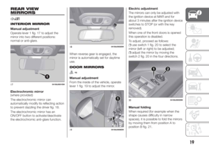 21
21 22
22 23
23 24
24 25
25 26
26 27
27 28
28 29
29 30
30 31
31 32
32 33
33 34
34 35
35 36
36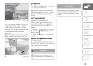 37
37 38
38 39
39 40
40 41
41 42
42 43
43 44
44 45
45 46
46 47
47 48
48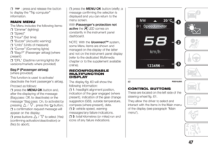 49
49 50
50 51
51 52
52 53
53 54
54 55
55 56
56 57
57 58
58 59
59 60
60 61
61 62
62 63
63 64
64 65
65 66
66 67
67 68
68 69
69 70
70 71
71 72
72 73
73 74
74 75
75 76
76 77
77 78
78 79
79 80
80 81
81 82
82 83
83 84
84 85
85 86
86 87
87 88
88 89
89 90
90 91
91 92
92 93
93 94
94 95
95 96
96 97
97 98
98 99
99 100
100 101
101 102
102 103
103 104
104 105
105 106
106 107
107 108
108 109
109 110
110 111
111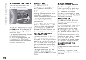 112
112 113
113 114
114 115
115 116
116 117
117 118
118 119
119 120
120 121
121 122
122 123
123 124
124 125
125 126
126 127
127 128
128 129
129 130
130 131
131 132
132 133
133 134
134 135
135 136
136 137
137 138
138 139
139 140
140 141
141 142
142 143
143 144
144 145
145 146
146 147
147 148
148 149
149 150
150 151
151 152
152 153
153 154
154 155
155 156
156 157
157 158
158 159
159 160
160 161
161 162
162 163
163 164
164 165
165 166
166 167
167 168
168 169
169 170
170 171
171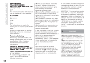 172
172 173
173 174
174 175
175 176
176 177
177 178
178 179
179 180
180 181
181 182
182 183
183 184
184 185
185 186
186 187
187 188
188 189
189 190
190 191
191 192
192 193
193 194
194 195
195 196
196 197
197 198
198 199
199 200
200 201
201 202
202 203
203 204
204 205
205 206
206 207
207 208
208 209
209 210
210 211
211 212
212 213
213 214
214 215
215 216
216 217
217 218
218 219
219 220
220 221
221 222
222 223
223 224
224 225
225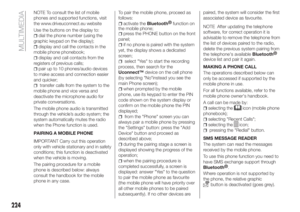 226
226 227
227 228
228 229
229 230
230 231
231 232
232 233
233 234
234 235
235 236
236 237
237 238
238 239
239 240
240 241
241 242
242 243
243