Page 266 of 553
General Information
The following regulatory statement applies to all Radio
Frequency (RF) devices equipped in this vehicle:
This device complies with Part 15 of the FCC Rules and
with Industry Canada license-exempt RSS standard(s).
Operation is subject to the following two conditions:
1. This device may not cause harmful interference.
2. This device must accept any interference received, in-cluding interference that may cause undesired opera-
tion.
NOTE: Changes or modifications not expressly approved
by the party responsible for compliance could void the
user ’s authority to operate the equipment.
Normal (Fixed Speed) Cruise Control Mode
In addition to Adaptive Cruise Control mode, a Normal
(Fixed Speed) Cruise Control mode is available for cruising
at fixed speeds. The Normal (Fixed Speed) Cruise Control
mode is designed to maintain a set cruising speed without
requiring the driver to operate the accelerator. Cruise
Control can only be operated if the vehicle speed is above
20 mph (32 km/h). To change between the different control modes, push the
Adaptive Cruise Control (ACC) on/off button which turns
the ACC and the Normal (Fixed Speed) Cruise Control off.
Pushing the Normal (Fixed Speed) Cruise Control on/off
button will result in turning on (changing to) the Normal
(Fixed Speed) Cruise Control mode.
WARNING!
In the Normal (Fixed Speed) Cruise Control mode, the
system will not react to vehicles ahead. In addition, the
proximity warning does not activate and no alarm will
sound even if you are too close to the vehicle ahead
since neither the presence of the vehicle ahead nor the
vehicle-to vehicle distance is detected. Be sure to
maintain a safe distance between your vehicle and the
vehicle ahead. Always be aware which mode is se-
lected.
264 STARTING AND OPERATING
Page 273 of 553
WARNING ALERTS
Rear Dis- tance
(in/cm) Greater
than
79 inches (200 cm) 79-59 inches
(200-150 cm)
59-47 inches
(150-120 cm)
47-39 inches
(120-100 cm)
39-25 inches
(100-65 cm) 25-12 inches
(65-30 cm) Less than
12 inches (30 cm)
Audible Alert
Chime None Single 1/2-
SecondTone
(for rear
center only) Slow
(for rear
center only) Slow
(for rear
center only) Fast
(for rear
center only) Fast Continuous
Arc — Left Rear None None None None None 2nd
Flashing1st Flashing
Arc —
Center Rear None 6th Solid 5th Solid 4th Solid 3rd
Flashing2nd
Flashing 1st Flashing
Arc — Right Rear None None None None None 2nd
Flashing1st Flashing
Radio
Volume
Reduced No
Yes YesYesYesYes Yes
6
STARTING AND OPERATING 271
Page 275 of 553

Cleaning The ParkSense System
Clean the Rear Park Assist sensors with water, car wash
soap and a soft cloth. Do not use rough or hard cloths. In
washing stations, clean sensors quickly keeping the vapor
jet/high pressure washing nozzles at least 4 inches (10 cm)
from the sensors. Do not scratch or poke the sensors.
Otherwise, you could damage the sensors.
ParkSense System Usage Precautions
NOTE:
•Ensure that the rear bumper is free of snow, ice, mud,
dirt and debris to keep the ParkSense system operating
properly.
• Jackhammers, large trucks, and other vibrations could
affect the performance of ParkSense or render the sys-
tem temporarily unavailable.
• When you turn ParkSense off in DRIVE, the instrument
cluster will display �PARKSENSE OFF� for five seconds.
Furthermore, once you turn ParkSense off, it remains off
until you turn it on again, even if you cycle the ignition.
• When you move the gear selector to the REVERSE
position and ParkSense is turned off, the instrument cluster display will show the “PARKSENSE OFF” mes-
sage for as long as the vehicle is in REVERSE.
• ParkSense will reduce the volume of the radio when it is
sounding an audio tone.
• Clean the ParkSense sensors regularly, taking care not to
scratch or damage them. The sensors must not be
covered with ice, snow, slush, mud, dirt or debris.
Failure to do so can result in the system not working
properly. The ParkSense system might not detect an
obstacle behind the fascia/bumper, or it could provide a
false indication that an obstacle is behind the fascia/
bumper.
• Ensure the ParkSense system is off if objects such as
bicycle carriers, trailer hitches, etc., are placed within 12
inches (30 cm) from the rear fascia/bumper. Failure to
do so can result in the system misinterpreting a close
object as a sensor problem, causing the “PARKSENSE
UNAVAILABLE SERVICE REQUIRED” message to be
shown in the instrument cluster display.6
STARTING AND OPERATING 273
Page 306 of 553
WARNING!
•If anyone in the vehicle could be in danger (e.g., fire
or smoke is visible, dangerous road conditions or
location), do not wait for voice contact from an
Emergency Services Agent. All occupants should exit
the vehicle immediately and move to a safe location.
• Never place anything on or near the vehicle’s oper-
able network and GPS antennas. You could prevent
operable network and GPS signal reception, which
can prevent your vehicle from placing an emergency
call. An operable network and GPS signal reception
is required for the SOS Call system to function
properly.
• The SOS Call system is embedded into the vehicle’s
electrical system. Do not add aftermarket electrical
equipment to the vehicle’s electrical system. This
may prevent your vehicle from sending a signal to
initiate an emergency call. To avoid interference that
can cause the SOS Call system to fail, never add
aftermarket equipment (e.g., two-way mobile radio,
CB radio, data recorder, etc.) to your vehicle’s electri-
cal system or modify the antennas on your vehicle. IF
YOUR VEHICLE LOSES BATTERY POWER FOR
(Continued)
WARNING! (Continued)
ANY REASON (INCLUDING DURING OR AFTER
AN ACCIDENT), THE UCONNECT FEATURES,
APPS AND SERVICES, AMONG OTHERS, WILL
NOT OPERATE.
• Modifications to any part of the SOS Call system
could cause the air bag system to fail when you need
it. You could be injured if the air bag system is not
there to help protect you.
SOS Call System Limitations
Vehicles sold in Mexico DO NOThave SOS Call system
capabilities.
SOS or other emergency line operators in Mexico may not
answer or respond to SOS system calls.
If the SOS Call system detects a malfunction, any of the
following may occur at the time the malfunction is de-
tected, and at the beginning of each ignition cycle:
• The Rearview Mirror light located between the ASSIST
and SOS buttons will continuously be illuminated red.
304 IN CASE OF EMERGENCY
Page 322 of 553
CavityCartridge Fuse Mini-FuseDescription
31 –25 Amp Breaker Power Seats – If Equipped
32 –15 Amp Blue HVAC Module/Cluster
33 –15 Amp Blue Ignition Switch/RF Hub
Module/Steering Column
Lock (300) – If Equipped
34 –10 Amp Red Steering Column Module/
Clock (300)
35 –5 Amp Tan Battery Sensor
36 –15 Amp Blue Electronic Exhaust Valve –
If Equipped
37 –20 Amp Yellow Radio
38 –20 Amp Yellow Power Outlet Inside Arm
Rest/Console Media Hub
40 30 Amp Pink –Fuel Pump (6.2L SRT De-
mon – If Equipped)
41 30 Amp Pink –Fuel Pump (6.2L SRT De-
mon – If Equipped)
42 30 Amp Pink –Rear Defrost
320 IN CASE OF EMERGENCY
Page 342 of 553
WARNING!
•Take care to avoid the radiator cooling fan whenever
the hood is raised. It can start anytime the ignition
switch is ON. You can be injured by moving fan
blades.
• Remove any metal jewelry such as rings, watch
bands and bracelets that could make an inadvertent
electrical contact. You could be seriously injured.
• Batteries contain sulfuric acid that can burn your
skin or eyes and generate hydrogen gas which is
flammable and explosive. Keep open flames or
sparks away from the battery.
1. Apply the parking brake, shift the automatic transmis- sion into PARK and place the ignition in the OFF
position.
2. Turn off the heater, radio, and all unnecessary electrical accessories.
3. If using another vehicle to jump start the battery, park the vehicle within the jumper cable’s reach, apply the
parking brake and make sure the ignition is OFF.
WARNING!
Do not allow vehicles to touch each other as this could
establish a ground connection and personal injury
could result.
Jump Starting Procedure
WARNING!
Failure to follow this jump starting procedure could
result in personal injury or property damage due to
battery explosion.
CAUTION!
Failure to follow these procedures could result in
damage to the charging system of the booster vehicle
or the discharged vehicle.
340 IN CASE OF EMERGENCY
Page 419 of 553
Leather Parts
Mopar Total Clean is specifically recommended for leather
upholstery.
Your leather upholstery can be best preserved by regular
cleaning with a damp soft cloth. Small particles of dirt can
act as an abrasive and damage the leather upholstery and
should be removed promptly with a damp cloth. Stubborn
soils can be removed easily with a soft cloth and Mopar
Total Clean. Care should be taken to avoid soaking your
leather upholstery with any liquid. Please do not use
polishes, oils, cleaning fluids, solvents, detergents, or
ammonia-based cleaners to clean your leather upholstery.
Application of a leather conditioner is not required to
maintain the original condition.
NOTE:If equipped with light colored leather, it tends to
show any foreign material, dirt, and fabric dye transfer
more so than darker colors. The leather is designed for easy
cleaning, and FCA recommends Mopar total care leather
cleaner applied on a cloth to clean the leather seats as
needed.
CAUTION!
Do not use Alcohol and Alcohol-based and/or Ketone
based cleaning products to clean leather seats, as
damage to the seat may result.
Glass Surfaces
All glass surfaces should be cleaned on a regular basis with
Mopar Glass Cleaner, or any commercial household-type
glass cleaner. Never use an abrasive type cleaner. Use
caution when cleaning the inside rear window equipped
with electric defrosters or windows equipped with radio
antennas. Do not use scrapers or other sharp instruments
that may scratch the elements.
When cleaning the rear view mirror, spray cleaner on the
towel or cloth that you are using. Do not spray cleaner
directly on the mirror.
8
SERVICING AND MAINTENANCE 417
Page 437 of 553
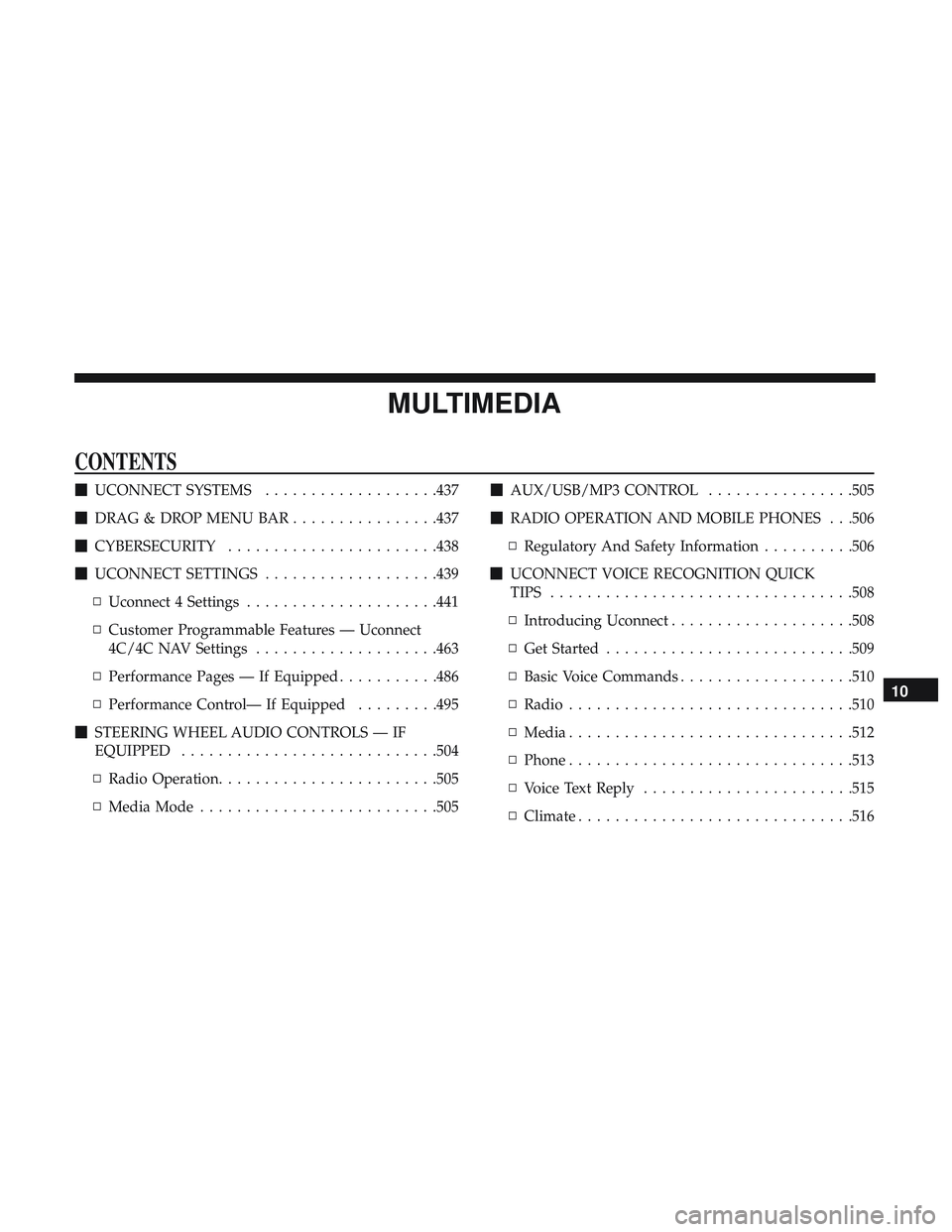
MULTIMEDIA
CONTENTS
�UCONNECT SYSTEMS ...................437
� DRAG & DROP MENU BAR ................437
� CYBERSECURITY .......................438
� UCONNECT SETTINGS ...................439
▫ Uconnect 4 Settings .....................441
▫ Customer Programmable Features — Uconnect
4C/4C NAV Settings ....................463
▫ Performance Pages — If Equipped ...........486
▫ Performance Control— If Equipped .........495
� STEERING WHEEL AUDIO CONTROLS — IF
EQUIPPED ............................504
▫ Radio Operation ........................505
▫ Media Mode ..........................505 �
AUX/USB/MP3 CONTROL ................505
� RADIO OPERATION AND MOBILE PHONES . . .506
▫ Regulatory And Safety Information ..........506
� UCONNECT VOICE RECOGNITION QUICK
TIPS .................................508
▫ Introducing Uconnect ....................508
▫ Get Started .......................... .509
▫ Basic Voice Commands ...................510
▫ Radio ...............................510
▫ Media ...............................512
▫ Phone ...............................513
▫ Voice Text Reply .......................515
▫ Climate ............................. .516
10