Page 158 of 553
 — If Equipped
The Blind Spot Monitoring (BSM) system uses two radar
sensors, located inside the rear bumper fascia, to detect
highway licensable")
AUXILIARY DRIVING SYSTEMS
Blind Spot Monitoring (BSM) — If Equipped
The Blind Spot Monitoring (BSM) system uses two radar
sensors, located inside the rear bumper fascia, to detect
highway licensable vehicles (automobiles, trucks, motor-
cycles, etc.) that enter the blind spot zones from the
rear/front/side of the vehicle.
When the vehicle is started, the BSM warning light will
momentarily illuminate in both outside rear view mirrors
to let the driver know that the system is operational.The BSM system sensors operate when the vehicle is in any
forward gear or REVERSE.
The BSM detection zone covers approximately one lane
width on both sides of the vehicle 12 ft (3.8 m). The zone
length starts at the outside rear view mirror and extends
approximately 10 ft (3 m) beyond the rear bumper of the
vehicle. The BSM system monitors the detection zones on
both sides of the vehicle when the vehicle speed reaches
approximately 6 mph (10 km/h) or higher and will alert
the driver of vehicles in these areas.
Rear Detection Zones
BSM Warning Light
156 SAFETY
Page 281 of 553

PARKVIEW REAR BACK UP CAMERA
Your vehicle is equipped with the ParkView Rear Back Up
Camera that allows you to see an on-screen image of the
rear surroundings of your vehicle whenever the gear
selector is put into REVERSE. The ParkView camera is
located on the rear of the vehicle above the rear license
plate. The image will be displayed in the touchscreen
display along with a caution note to “check entire sur-
roundings” across the top of the screen. After five seconds,
this note will disappear.
NOTE:The ParkView Rear Back Up Camera has program-
mable modes of operation that may be selected through the
Uconnect System. Refer to “Uconnect Settings” in “Multi-
media” for further information. If your vehicle is equipped with the Camera Delay feature
and it is turned on, the rear camera image will be displayed
for up to 10 seconds when the vehicle is shifted out of
REVERSE. However, this feature is canceled if the forward
vehicle speed exceeds 8 mph (13 km/h), the transmission is
shifted into PARK, the vehicle’s ignition is cycled to OFF, or
by pressing the image defeat [X] button.
When the vehicle is shifted out of REVERSE (with Camera
Delay turned off), the rear camera mode is exited and the
last touchscreen appears again.
When enabled, active guide lines are overlaid on the image
to illustrate the width of the vehicle and its projected
backup path based on the steering wheel position. The
active guide lines will show separate zones that will help
indicate the distance to the rear of the vehicle.
Different colored zones indicate the distance to the rear of
the vehicle.
6
STARTING AND OPERATING 279
Page 288 of 553

The GVWR is the total allowabl")
Common Towing Definitions
The following trailer towing related definitions will assist
you in understanding the following information:
Gross Vehicle Weight Rating (GVWR)
The GVWR is the total allowable weight of your vehicle.
This includes driver, passengers, cargo and tongue weight.
The total load must be limited so that you do not exceed
the GVWR. Refer to “Vehicle Loading/Vehicle Certification
Label” in “Starting And Operating” for further informa-
tion.
Gross Trailer Weight (GTW)
The GTW is the weight of the trailer plus the weight of all
cargo, consumables, and equipment (permanent or tempo-
rary) loaded in or on the trailer in its�loaded and ready for
operation� condition.
The recommended way to measure GTW is to put your
fully loaded trailer on a vehicle scale. The entire weight of
the trailer must be supported by the scale.
Gross Combination Weight Rating (GCWR)
The GCWR is the total allowable weight of your vehicle
and trailer when weighed in combination.
Gross Axle Weight Rating (GAWR)
The GAWR is the maximum capacity of the front and rear
axles. Distribute the load over the front and rear axles
evenly. Make sure that you do not exceed either front or
rear GAWR. Refer to “Vehicle Loading/Vehicle Certifica-
tion Label” in “Starting And Operating” for further infor-
mation.
WARNING!
It is important that you do not exceed the maximum
front or rear GAWR. A dangerous driving condition
can result if either rating is exceeded. You could lose
control of the vehicle and have a collision.
Tongue Weight (TW)
The tongue weight is the downward force exerted on the
hitch ball by the trailer. You must consider this as part of
the load on your vehicle.
Trailer Frontal Area
The frontal area is the maximum height multiplied by the
maximum width of the front of a trailer.
286 STARTING AND OPERATING
Page 392 of 553
 — Metric tire sizing is based on U.S.
design standards. P-Metric tires have the letter “P”
molded into the sidewall preceding the size designation.
Example: P215/65R15 95H")
NOTE:
•P (Passenger) — Metric tire sizing is based on U.S.
design standards. P-Metric tires have the letter “P”
molded into the sidewall preceding the size designation.
Example: P215/65R15 95H.
• European — Metric tire sizing is based on European
design standards. Tires designed to this standard have
the tire size molded into the sidewall beginning with the
section width. The letter �P�is absent from this tire size
designation. Example: 215/65R15 96H.
• LT (Light Truck) — Metric tire sizing is based on U.S.
design standards. The size designation for LT-Metric
tires is the same as for P-Metric tires except for the letters
“LT” that are molded into the sidewall preceding the
size designation. Example: LT235/85R16. •
Temporary spare tires are designed for temporary emer-
gency use only. Temporary high pressure compact spare
tires have the letter “T” or “S” molded into the sidewall
preceding the size designation. Example: T145/80D18
103M.
• High flotation tire sizing is based on U.S. design stan-
dards and it begins with the tire diameter molded into
the sidewall. Example: 31x10.5 R15 LT.
390 SERVICING AND MAINTENANCE
Page 393 of 553
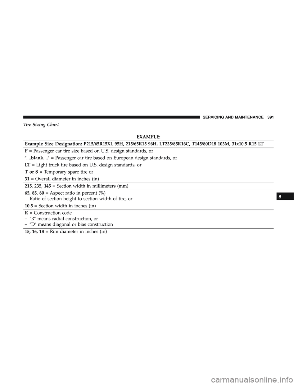
Tire Sizing Chart
EXAMPLE:
Example Size Designation: P215/65R15XL 95H, 215/65R15 96H, LT235/85R16C, T145/80D18 103M, 31x10.5 R15 LT
P = Passenger car tire size based on U.S. design standards, or
�....blank....� = Passenger car tire based on European design standards, or
LT = Light truck tire based on U.S. design standards, or
TorS= Temporary spare tire or
31 = Overall diameter in inches (in)
215, 235, 145 = Section width in millimeters (mm)
65, 85, 80 = Aspect ratio in percent (%)
–Ratio of section height to section width of tire, or
10.5 = Section width in inches (in)
R = Construction code
–�R� means radial construction, or
–�D� means diagonal or bias construction
15, 16, 18 = Rim diameter in inches (in)
8
SERVICING AND MAINTENANCE 391
Page 471 of 553

Setting NameSelectable Options
Active ParkView Backup Camera Guidelines On
Off
NOTE:
The “Active ParkView Backup Camera Guidelines” feature overlays the Rear Backup Camera image with active, or
dynamic, grid lines to help illustrate the width of the vehicle and its project back up path, based on the steering
wheel position when the option is checked. A dashed center line overlay indicates the center of the vehicle to assist
with parking or aligning to a hitch/receiver.
Safety & Driving Assistance
After pressing the “Safety & Driving Assistance” button on
the touchscreen, the following settings will be available:
Setting Name Selectable Options
Forward Collision Warn-
ing On/Off — If Equipped On
Off
NOTE:
Changing the FCW status to “Off” prevents the system from warning you of a possible collision with the vehicle in
front of you.
The FCW system state is kept in memory from one ignition cycle to the next. If the system is turned off, it will re-
main off when the vehicle is restarted.
10
MULTIMEDIA 469