2018 DODGE CHARGER radio
[x] Cancel search: radioPage 53 of 553

Front Heated Seats
The front heated seat control buttons are located within the
climate or controls screen of the touchscreen.
You can choose from HI, LO, or OFF heat settings. The
indicator arrows in touchscreen buttons indicate the level
of heat in use. Two indicator arrows will illuminate for HI,
and one for LO. Turning the heating elements off will
return the user to the radio screen.
•Press the heated seat button
once to turn the HI
setting on.
• Press the heated seat buttona second time to turn
the LO setting on.
• Press the heated seat buttona third time to turn the
heating elements off.
If the HI-level setting is selected, the system will automati-
cally switch to LO-level after approximately 60 minutes of
continuous operation. At that time, the display will change
from HI to LO, indicating the change. The LO-level setting
will turn off automatically after approximately 45 minutes. NOTE:
•
Once a heat setting is selected, heat will be felt within
two to five minutes.
• The engine must be running for the heated seats to
operate.
Vehicles Equipped With Remote Start
On models that are equipped with remote start, the heated
seats can be programmed to come on during a remote start.
This feature can be programmed through the Uconnect
system. Refer to “Uconnect Settings” in “Multimedia” for
further information.
WARNING!
• Persons who are unable to feel pain to the skin
because of advanced age, chronic illness, diabetes,
spinal cord injury, medication, alcohol use, exhaus-
tion or other physical condition must exercise care
when using the seat heater. It may cause burns even
at low temperatures, especially if used for long
periods of time.
(Continued)
3
GETTING TO KNOW YOUR VEHICLE 51
Page 75 of 553
Parade Mode (Daytime Brightness Feature)
Rotate the instrument panel dimmer control upward to the
first detent. This feature brightens all text displays such as
the odometer, instrument cluster display, and radio when
the position lights or headlights are on.
WINDSHIELD WIPERS AND WASHERS
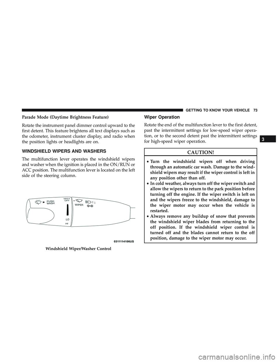
The multifunction lever operates the windshield wipers
and washer when the ignition is placed in the ON/RUN or
ACC position. The multifunction lever is located on the left
side of the steering column.
Wiper Operation
Rotate the end of the multifunction lever to the first detent,
past the intermittent settings for low-speed wiper opera-
tion, or to the second detent past the intermittent settings
for high-speed wiper operation.
CAUTION!
•Turn the windshield wipers off when driving
through an automatic car wash. Damage to the wind-
shield wipers may result if the wiper control is left in
any position other than off.
• In cold weather, always turn off the wiper switch and
allow the wipers to return to the park position before
turning off the engine. If the wiper switch is left on
and the wipers freeze to the windshield, damage to
the wiper motor may occur when the vehicle is
restarted.
• Always remove any buildup of snow that prevents
the windshield wiper blades from returning to the
off position. If the windshield wiper control is
turned off and the blades cannot return to the off
position, damage to the wiper motor may occur.
Windshield Wiper/Washer Control
3
GETTING TO KNOW YOUR VEHICLE 73
Page 104 of 553
GARAGE DOOR OPENER — IF EQUIPPED
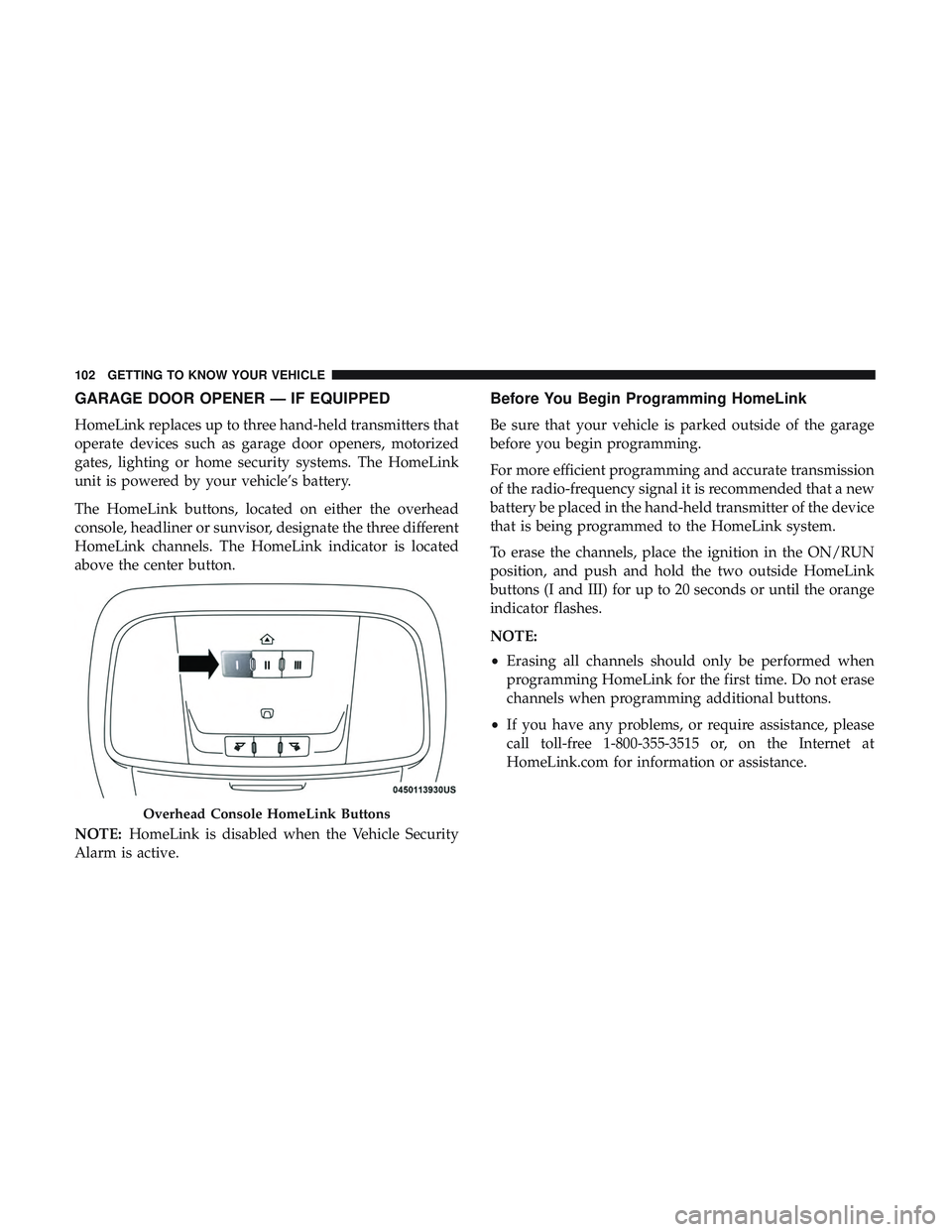
HomeLink replaces up to three hand-held transmitters that
operate devices such as garage door openers, motorized
gates, lighting or home security systems. The HomeLink
unit is powered by your vehicle’s battery.
The HomeLink buttons, located on either the overhead
console, headliner or sunvisor, designate the three different
HomeLink channels. The HomeLink indicator is located
above the center button.
NOTE:HomeLink is disabled when the Vehicle Security
Alarm is active.
Before You Begin Programming HomeLink
Be sure that your vehicle is parked outside of the garage
before you begin programming.
For more efficient programming and accurate transmission
of the radio-frequency signal it is recommended that a new
battery be placed in the hand-held transmitter of the device
that is being programmed to the HomeLink system.
To erase the channels, place the ignition in the ON/RUN
position, and push and hold the two outside HomeLink
buttons (I and III) for up to 20 seconds or until the orange
indicator flashes.
NOTE:
• Erasing all channels should only be performed when
programming HomeLink for the first time. Do not erase
channels when programming additional buttons.
• If you have any problems, or require assistance, please
call toll-free 1-800-355-3515 or, on the Internet at
HomeLink.com for information or assistance.
Overhead Console HomeLink Buttons
102 GETTING TO KNOW YOUR VEHICLE
Page 107 of 553
2. Place the hand-held transmitter 1 to 3 inches (3 to 8 cm)away from the HomeLink button you wish to program
while keeping the HomeLink indicator light in view.
3. Press and hold the HomeLink button you want to program while you press and hold the hand-held trans-
mitter button.
4. Continue to hold both buttons and observe the indicator light. The HomeLink indicator will flash slowly and
then rapidly after HomeLink has received the frequency
signal from the hand-held transmitter. Release both
buttons after the indicator light changes from slow to
rapid.
5. Press and hold the programmed HomeLink button and observe the indicator light.
• If the indicator light stays on constantly, programming
is complete and the garage door/device should acti-
vate when the HomeLink button is pressed.
• To program the two remaining HomeLink buttons,
repeat each step for each remaining button. DO NOT
erase the channels. Reprogramming A Single HomeLink Button (Non-
Rolling Code)
To reprogram a channel that has been previously trained,
follow these steps:
1. Cycle the ignition to the ON/RUN position.
2. Press and hold the desired HomeLink button until the
indicator light begins to flash after 20 seconds. Do not
release the button.
3. Without releasing the button, proceed with “Program- ming A Non-Rolling Code” step 2 and follow all remain-
ing steps.
Canadian/Gate Operator Programming
For programming transmitters in Canada/United States
that require the transmitter signals to “time-out” after
several seconds of transmission.
Canadian radio frequency laws require transmitter signals
to time-out (or quit) after several seconds of transmission –
which may not be long enough for HomeLink to pick up
the signal during programming. Similar to this Canadian
law, some U.S. gate operators are designed to time-out in
the same manner.
3
GETTING TO KNOW YOUR VEHICLE 105
Page 110 of 553
WARNING!
•Vehicle exhaust contains carbon monoxide, a danger-
ous gas. Do not run your vehicle in the garage while
programming the transceiver. Exhaust gas can cause
serious injury or death.
• Your motorized door or gate will open and close
while you are programming the universal trans-
ceiver. Do not program the transceiver if people, pets
or other objects are in the path of the door or gate.
Only use this transceiver with a garage door opener
that has a “stop and reverse” feature as required by
Federal safety standards. This includes most garage
door opener models manufactured after 1982. Do not
use a garage door opener without these safety fea-
tures. Call toll-free 1-800-355-3515 or, on the Internet
at HomeLink.com for safety information or assis-
tance.
General Information
The following regulatory statement applies to all Radio
Frequency (RF) devices equipped in this vehicle:
This device complies with Part 15 of the FCC Rules and
with Innovation, Science and Economic Development
Canada license-exempt RSS standard(s). Operation is sub-
ject to the following two conditions:
1. This device may not cause harmful interference, and
2. This device must accept any interference received, in-
cluding interference that may cause undesired opera-
tion.
NOTE: Changes or modifications not expressly approved
by the party responsible for compliance could void the
user ’s authority to operate the equipment.
108 GETTING TO KNOW YOUR VEHICLE
Page 129 of 553
LaneSense — If Equipped
The instrument cluster display displays the current Lane-
Sense system settings. The information displayed depends
on LaneSense system status and the conditions that need to
be met. For further information, refer to “LaneSense — If
Equipped” in “Starting And Operating.”
Fuel Economy
Two submenu pages; one with Current Value (instanta-
neous calculation of the fuel economy) displayed and one
without the Current Value displayed (toggle theleftor
right arrow button to select one):
• Current Fuel Economy (MPG, L/100 km, or km/L).
• Range To Empty (miles or km).
• Average Fuel Economy (MPG, L/100 km, or km/L).
• The Max and Min values will correspond to the particu-
lar engine requirements.
• Lower end of gauge will be displayed in an amber color
and turn green as Fuel Economy improves.
• Hold the OKbutton to reset average fuel economy
information.
Trip Info
Push and release the upordown arrow button until the
Trip Menu item is displayed in the instrument cluster
display. Toggle the leftorright arrow button to select Trip
A or Trip B. The Trip information will display the follow-
ing:
• Distance – Shows the total distance (mi or km) traveled
for Trip A or Trip B since the last reset.
• Average Fuel Economy – Shows the average fuel
economy (MPG, L/100km or km/L) of Trip A or Trip B
since the last reset.
• Elapsed Time – Shows the total elapsed time of travel
since the last reset.
Hold the OKbutton to reset feature information.
Audio
This menu displays the Audio information of the currently
playing audio source (e.g. FM radio).
Messages
This feature shows the number of stored warning mes-
sages, if any. Pushing the rightorleft arrow button will
allow you to scroll through the stored messages.
4
GETTING TO KNOW YOUR INSTRUMENT PANEL 127
Page 132 of 553
The electrical loads that may be switched off (if equipped),
and vehicle functions which can be affected by load
reduction:
•Heated Seat/Vented Seats/Heated Wheel
• Heated/Cooled Cup Holders — If Equipped
• Rear Defroster And Heated Mirrors
• HVAC System
• 115V AC Power Inverter System
• Audio and Telematics System
Loss of the battery charge may indicate one or more of the
following conditions:
• The charging system cannot deliver enough electrical
power to the vehicle system because the electrical loads
are larger than the capability of charging system. The
charging system is still functioning properly.
• Turning on all possible vehicle electrical loads (e.g.
HVAC to max settings, exterior and interior lights,
overloaded power outlets +12V, 115V AC, USB ports)
during certain driving conditions (city driving, towing,
frequent stopping). •
Installing options like additional lights, upfitter electri-
cal accessories, audio systems, alarms and similar de-
vices.
• Unusual driving cycles (short trips separated by long
parking periods).
• The vehicle was parked for an extended period of time
(weeks, months).
• The battery was recently replaced and was not charged
completely.
• The battery was discharged by an electrical load left on
when the vehicle was parked.
• The battery was used for an extended period with the
engine not running to supply radio, lights, chargers,
+12V portable appliances like vacuum cleaners, game
consoles and similar devices.
130 GETTING TO KNOW YOUR INSTRUMENT PANEL
Page 148 of 553
SAFETY FEATURES
Anti-Lock Brake System (ABS)
The Anti-Lock Brake System (ABS) provides increased
vehicle stability and brake performance under most brak-
ing conditions. The system automatically prevents wheel
lock, and enhances vehicle control during braking.
The ABS performs a self-check cycle to ensure that the ABS
is working properly each time the vehicle is started and
driven. During this self-check, you may hear a slight
clicking sound as well as some related motor noises.
ABS is activated during braking when the system detects
one or more wheels begin to lock. Road conditions such as
ice, snow, gravel, bumps, railroad tracks, loose debris, or
panic stops may increase the likelihood of ABS activa-
tion(s).
You also may experience the following when ABS activates:
•The ABS motor noise (it may continue to run for a short
time after the stop).
• The clicking sound of solenoid valves.
• Brake pedal pulsations.
• A slight drop of the brake pedal at the end of the stop. These are all normal characteristics of ABS.
WARNING!
•
The ABS contains sophisticated electronic equip-
ment that may be susceptible to interference caused
by improperly installed or high output radio trans-
mitting equipment. This interference can cause pos-
sible loss of anti-lock braking capability. Installation
of such equipment should be performed by qualified
professionals.
• Pumping of the Anti-Lock Brakes will diminish their
effectiveness and may lead to a collision. Pumping
makes the stopping distance longer. Just press firmly
on your brake pedal when you need to slow down or
stop.
• The ABS cannot prevent the natural laws of physics
from acting on the vehicle, nor can it increase brak-
ing or steering efficiency beyond that afforded by the
condition of the vehicle brakes and tires or the
traction afforded.
• The ABS cannot prevent collisions, including those
resulting from excessive speed in turns, following
another vehicle too closely, or hydroplaning.
(Continued)
146 SAFETY