Page 187 of 317
185
C4-cactus_en_Chap08_En-cas-de-panne_ed01-2016
The tyre inflation pressures are given on this label.
This
k
it
i
s
i
nstalled
i
n
t
he
s
torage
b
ox,
u
nder
t
he
b
oot
floor.
This
kit
consists
of
a
compressor
and
a
sealant
c
artridge.
It allows the temporary repair
of
a
tyre.
You
are
then
able
to
go
to
the
nearest
garage.
It
is
designed
to
repair
most
punctures
which
c
ould affect the tyre, located on the tyre tread
or
shoulder.
Its
compressor
can
be
used
to
check
and
a
djust
the
pressure
of
the
tyre.
Temporary pu
ncture r epair k it
Access to the kit
List of tools
These tools are specific to your vehicle and can
vary
according to equipment. Do not use them
f
or other purposes.
1.
1
2 V compressor.
C
ontains a sealant cartridge for the
t
emporary repair of a tyre and can also be
u
sed for adjusting tyre pressures.
2.
T
owing eye.
For
more information on towing refer to the
c
orresponding
s
ection.
8
In the event of a breakdown
Page 188 of 317
186
C4-cactus_en_Chap08_En-cas-de-panne_ed01-2016
A. "Sealant" or "Air" position selector.
B. On "I"
/ off "O" s witch.
C.
D
eflation button.
D.
P
ressure gauge (in bars and psi).
E.
C
ompartment
h
ousing:
-
a
cable with adaptor for 12 V socket,
-
v
arious inflation adaptors for
accessories, such as balls,
bicycle tyres...
Description of the kit
The speed limit sticker I must be affixed t o the vehicle's steering wheel to remind
y
ou that a wheel is in temporary use.
Do
not exceed a speed of 50 mph
(
80 km/h) when driving with a tyre
r
epaired using this type of kit.
F.
S
ealant
c
artridge.
G.
W
hite pipe with cap for repair.
H.
B
lack pipe for inflation.
I.
S
peed limit sticker.
In the event of a breakdown
Page 189 of 317
187
C4-cactus_en_Chap08_En-cas-de-panne_ed01-2016
1. Sealing
Repair procedure
Avoid removing any foreign bodies which have penetrated into the tyre.F
U
ncoil the white pipe G
f
ully.
F
U
nscrew the cap from the white pipe.
F
C
onnect the white pipe to the valve of the
tyre to be repaired.
F
S
witch off the ignition.
F
T
urn the selector A to the
"Sealant"
p
osition.
F
C
heck that the switch B is in
position "O" . F
C
onnect the compressor's electric plug to
t
he vehicle's 12 V socket.
F
S
tart the vehicle and leave the engine
r
unning.
Take care, this product is harmful if s
wallowed and causes irritation to the eyes.
Keep this product out of the reach of
children.Do not start the compressor before c onnecting the white pipe to the tyre
v
alve: the sealant product would be
e
xpelled through the pipe.
8
In the event of a breakdown
Page 190 of 317

188
C4-cactus_en_Chap08_En-cas-de-panne_ed01-2016
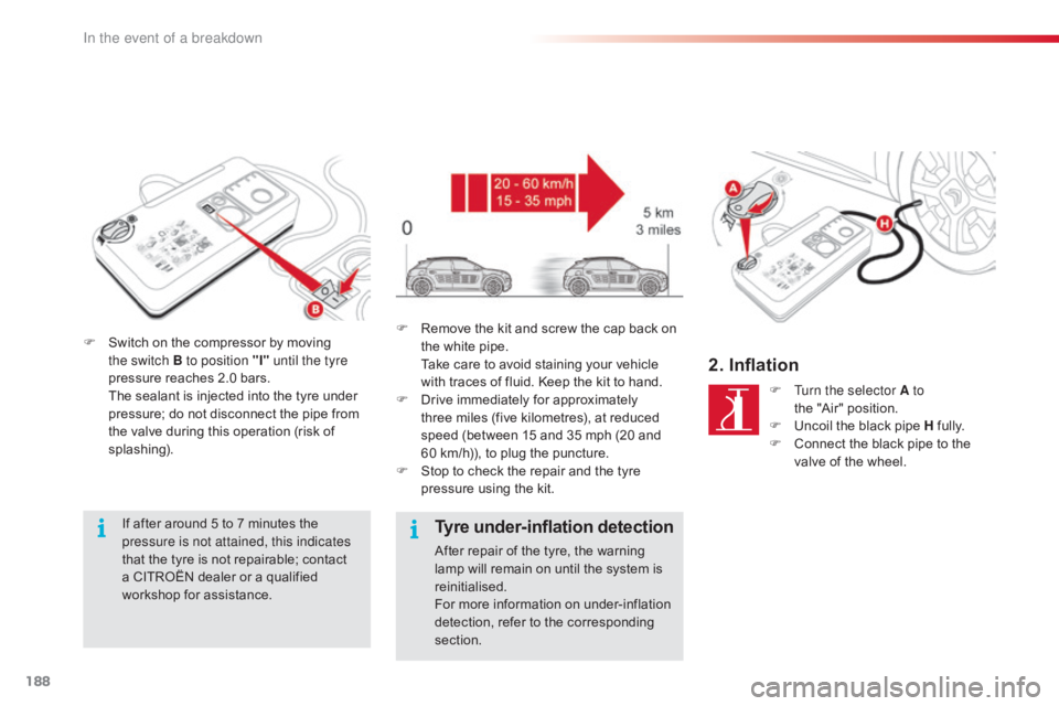
F Switch on the compressor by moving t
he switch B to position "I" until the tyre
pressure
reaches 2.0 bars.
T
he sealant is injected into the tyre under
p
ressure; do not disconnect the pipe from
t
he valve during this operation (risk of
sp
lashing).
If
after around 5 to 7 minutes the
p
ressure is not attained, this indicates
that
the tyre is not repairable; contact
a
CITROËN dealer or a qualified
w
orkshop for assistance. F
R emove the kit and screw the cap back on t
he white pipe.
T
ake care to avoid staining your vehicle
w
ith traces of fluid. Keep the kit to hand.
F
D
rive immediately for approximately
t
hree miles (five kilometres), at reduced
s
peed (between 15 and 35 mph (20 and
6
0 km/h)), to plug the puncture.
F
S
top to check the repair and the tyre
p
ressure using the kit.
Tyre under-inflation detection
After repair of the tyre, the warning lamp will remain on until the system is
r
einitialised.
For
more information on under-inflation
d
etection, refer to the corresponding
s
ection.
2. Inflation
F Turn the selector A to the "Air" position.
F
U
ncoil the black pipe H
f
ully.
F
C
onnect the black pipe to the
v
alve of the wheel.
In the event of a breakdown
Page 191 of 317

189
C4-cactus_en_Chap08_En-cas-de-panne_ed01-2016
Removing the cartridge
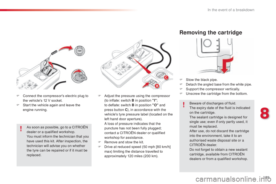
F Stow the black pipe.
F Detach the angled base from the white pipe.F Support the compressor vertically.
F U nscrew the cartridge from the bottom.
Beware
of discharges of fluid.
The
expiry date of the fluid is indicated
o
n the cartridge.
The
sealant cartridge is designed for
s
ingle use; even if only partly used, it
m
ust be replaced.
After
use, do not discard the cartridge
i
nto the environment, take it to an
a
uthorised waste disposal site or a
CITROËN
dealer.
Do
not forget to obtain a new sealant
c
artridge, available from CITROËN
d
ealers or from a qualified workshop.
F
C
onnect
the
compressor's
electric
plug
to
t
he
vehicle's
12
V
socket.
F
S
tart
the
vehicle
again
and
leave
the
e
ngine
r
unning.
As
soon
as
possible,
go
to
a
CITROËN
d
ealer
or
a
qualified
workshop.
You
must
inform
the
technician
that
you
h
ave
used
this
kit.
After
inspection,
the
t
echnician will advise you on whether
the
tyre
can
be
repaired
or
if
it
must
be
r
eplaced. F
A
djust
the
pressure
using
the
compressor
(
to
inflate:
switch
B in position "I" ;
t
o deflate:
switch
B
in position "O" and
press button C ), in accordance with the
vehicle's
t
yre
pressure
label
(located
on
the
l
eft
hand
door
aperture).
A l
oss of pressure indicates that the
puncture
has
not
been
fully
plugged;
c
ontact
a
CITROËN
dealer
or
qualified
w
orkshop
for
assistance.
F
R
emove
and
stow
the
kit.
F
D
rive
at
reduced
speed
(50
mph
[80
km/h]
m
ax)
limiting
the
distance
travelled
to
a
pproximately
120
miles
(200
km).
8
In the event of a breakdown
Page 192 of 317

190
C4-cactus_en_Chap08_En-cas-de-panne_ed01-2016
Checking tyre pressures / inflating accessories
You can also use the compressor, without injecting any product, to:
-
c
heck or adjust the pressure of your tyres,
-
i
nflate other accessories (balls, bicycle
tyres...).
F
T
urn the selector A to the
"Air" position.
F
U
ncoil the black pipe H
f
ully.F
C onnect the compressor's electrical
c
onnector to the vehicle's 12 V socket.
F
S
tart the vehicle and let the engine run.
F
A
djust the pressure using the compressor
(
to inflate: switch B in position "I";
t
o deflate: switch B in position "O" and
press button C ),
according to the vehicle's
t
yre pressure label or the accessory's
p
ressure label.
F
R
emove the kit then stow it.Should
the pressure of one or more
t
yres be adjusted, it is necessary to
r
einitialise the under-inflation detection
system.
For
more information on under-inflation
d
etection, refer to the corresponding
s
ection.
F
C
onnect the black pipe to the valve of the
w
heel or accessory.
I
f necessary, fit one of the adaptors
supplied
with the kit first.
In the event of a breakdown
Page 193 of 317

191
C4-cactus_en_Chap08_En-cas-de-panne_ed01-2016
Spare wheel
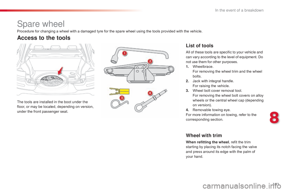
The tools are installed in the boot under the
floor, or may be located, depending on version,
u
nder
t
he
f
ront
p
assenger
sea
t.
Access to the tools
List of tools
All of these tools are specific to your vehicle and
can vary according to the level of equipment. Do n
ot use them for other purposes.
1.
W
heelbrace.
F
or removing the wheel trim and the wheel
bol
ts.
2.
J
ack with integral handle.
F
or raising the vehicle.
3.
W
heel bolt cover removal tool.
F
or removing the wheel bolt covers on alloy
w
heels
o
r
t
he
c
entral
w
heel
c
ap
(
depending
o
n version).
4.
R
emovable towing eye.
For
more information on towing, refer to the
c
orresponding
s
ection.
Procedure
for
changing
a
wheel
with
a
damaged
tyre
for
the
spare
wheel
using
the
tools
provided
with
the vehicle.
Wheel with trim
When refitting the wheel
, refit the trim s
tarting by placing its notch facing the valve
a
nd press around its edge with the palm of
y
our hand.
8
In the event of a breakdown
Page 194 of 317
192
C4-cactus_en_Chap08_En-cas-de-panne_ed01-2016
Taking out the wheel
F Unclip the tool storage box (standard spare w
heel).
F
U
nscrew the central nut.
F
R
emove the fixing parts (nut and bolt).
F
P
ull the spare wheel towards you from the
r
e a r.
F
T
ake the wheel out of the boot.
The spare wheel is installed in the boot under
the
floor.
Depending
on
the
engine,
the
spare
wheel
is
a s
tandard wheel or the "space-saver" type
(BlueHDi
100).
Access to the spare wheel
Putting the wheel back in place
F Put the wheel back in its housing.
F U nscrew the nut on the bolt by a few turns.
F
R
eposition the fixing parts (nut and bolt) in
t
he centre of the wheel.
F
T
ighten fully until the central nut clicks to
r
etain the wheel correctly.
F
C
lip the tool storage box back into place
(
standard
spar
e
w
heel).
In the absence of a wheel in the spare wheel
well,
the fixing parts (nut and bolt) cannot be
r
efitted.
In the event of a breakdown