Page 170 of 696

Sun Screens — If Equipped
Sun screens are available for second and third row seating
windows. The screens store in the sill trim panels, and the
tops of the windows are equipped with hooks that the sun
screens attach to when pulled out.
Gently pull up on the tab to raise the sun screen. Continue
pulling the sun screen until the tab is near the top of the
window.
Once the screen is completely to the top of the window,
extend the top bar of the sun screen over the two hooks
attached to the top of the window.To lower the sun screen, gently lift the tab upward to
disengage the hooks, and feed the screen back into the base
sill.
Power Outlets
Your vehicle is equipped with 12 Volt (15 Amp) power
outlets, and 5 Volt (2.5 Amp) USB power outlets, that can
be used to power cellular phones, small electronics and
other low powered electrical accessories. The power outlets
can be labeled with either a “key” or a “battery” symbol to
indicate how the outlet is powered. Power outlets labeled
with a “key” are powered when the ignition is in the ON orSun Screen Retracted
Sun Screen Extended
168 GETTING TO KNOW YOUR VEHICLE
Page 171 of 696
ACC position, while the outlets labeled with a “battery”
are connected directly to the battery and powered at all
times.
NOTE:
•All accessories connected to the “battery” powered
outlets should be removed or turned off when the
vehicle is not in use to protect the battery against
discharge.
CAUTION!
Power outlets are designed for accessory plugs only.
Do not insert any other object in the power outlets as
this will damage the outlet and blow the fuse. Im-
proper use of the power outlet can cause damage not
covered by your New Vehicle Limited Warranty.
The front power outlet is located at the bottom of the
instrument panel. In addition to the front power outlets, there is also a power
outlet located in the rear cargo area.
The rear power outlet is located in the right rear cargo area.12 Volt Front Power Outlet
3
GETTING TO KNOW YOUR VEHICLE 169
Page 172 of 696
NOTE:The USB outlet in the bottom of the instrument
panel can be switched from “ignition” only to constant
“battery” powered all the time. See an authorized dealer
for details.
WARNING!
To avoid serious injury or death:
• Only devices designed for use in this type of outlet
should be inserted into any 12 Volt outlet.
• Do not touch with wet hands.
(Continued)
Rear Power OutletPower Outlet Fuse Locations
1 — F95A-F95B USB IP 10A
2 — F85 Cigar Lighter 20A
3 — F60 RR Cargo Power Outlet 20A
170 GETTING TO KNOW YOUR VEHICLE
Page 173 of 696

WARNING!(Continued)
•Close the lid when not in use and while driving the
vehicle.
• If this outlet is mishandled, it may cause an electric
shock and failure.
CAUTION!
•Many accessories that can be plugged in draw power
from the vehicle’s battery, even when not in use (i.e.,
cellular phones, etc.). Eventually, if plugged in long
enough, the vehicle’s battery will discharge suffi-
ciently to degrade battery life and/or prevent the
engine from starting.
• Accessories that draw higher power (i.e., coolers,
vacuum cleaners, lights, etc.) will degrade the battery
even more quickly. Only use these intermittently and
with greater caution.
• After the use of high power draw accessories, or long
periods of the vehicle not being started (with acces-
sories still plugged in), the vehicle must be driven a
sufficient length of time to allow the generator to
recharge the vehicle’s battery.
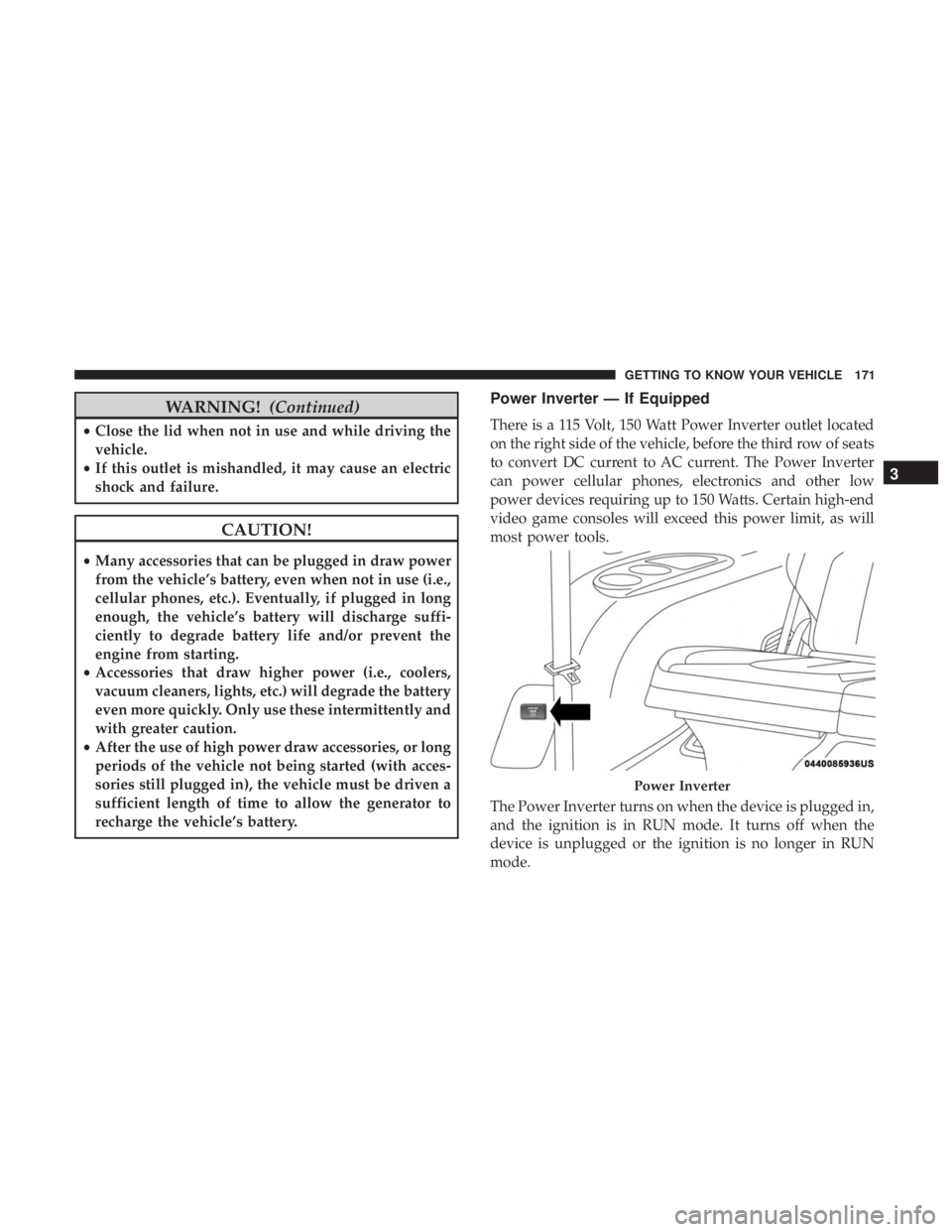
Power Inverter — If Equipped
There is a 115 Volt, 150 Watt Power Inverter outlet located
on the right side of the vehicle, before the third row of seats
to convert DC current to AC current. The Power Inverter
can power cellular phones, electronics and other low
power devices requiring up to 150 Watts. Certain high-end
video game consoles will exceed this power limit, as will
most power tools.
The Power Inverter turns on when the device is plugged in,
and the ignition is in RUN mode. It turns off when the
device is unplugged or the ignition is no longer in RUN
mode.
Power Inverter
3
GETTING TO KNOW YOUR VEHICLE 171
Page 183 of 696

GETTING TO KNOW YOUR INSTRUMENT PANEL
CONTENTS
�INSTRUMENT CLUSTER ..................182
▫ Instrument Cluster Descriptions ............183
� INSTRUMENT CLUSTER DISPLAY ...........185
▫ Instrument Cluster Display Location And
Controls ............................ .185
▫ Oil Life Reset ........................ .187
▫ KeySense Cluster Messages — If Equipped .....188
▫ Instrument Cluster Display Menu Items ......189
▫ Battery Saver On/Battery Saver Mode
Message — Electrical Load Reduction
Actions — If Equipped ..................195
� TRIP COMPUTER .......................197 �
WARNING LIGHTS AND MESSAGES .........197
▫ Red Warning Lights .....................198
▫ Yellow Warning Lights ...................202
▫ Yellow Indicator Lights ...................206
▫ Green Indicator Lights ...................206
▫ Blue Indicator Lights ....................208
▫ White Indicator Lights ...................208
� ONBOARD DIAGNOSTIC SYSTEM — OBD II . . .209
▫ Onboard Diagnostic System (OBD II)
Cybersecurity ........................ .209
� EMISSIONS INSPECTION AND MAINTENANCE
PROGRAMS .......................... .2104
Page 188 of 696

•Down Arrow Button
Push and release the downarrow button to scroll
downward through the Main Menu items.
• Right Arrow Button
Push and release the rightarrow button to access
the information screens or submenu screens of a
main menu item.
• Back/Left Arrow Button
Push and release the leftarrow button to access
the information screens or submenu screens of a
main menu item.
• OK Button
Push the OKbutton to access/select the information
screens or submenu screens of a Main Menu item. Push
and hold the OKbutton for two seconds to reset
displayed/selected features that can be reset. The instrument cluster display (base/premium cluster)
features a driver-interactive display that is located in the
center of the instrument cluster, and may include the
following menu/submenu items:
Speedometer
•
MPH
• km/h
Vehicle Info
• Tire Pressure Monitor
• Coolant Temp
• Battery Voltage
• Trans Temp
• Oil Temp
• Oil Pressure
• Oil Life (Hold OK To Reset)
• Battery Voltage
• Engine Hours — If Equipped
186 GETTING TO KNOW YOUR INSTRUMENT PANEL
Page 191 of 696

Instrument Cluster Display Menu Items
NOTE:The instrument cluster display menu items display
in the center of the instrument cluster. Menu items may
vary depending on your vehicle features.
Speedometer
Push and release the upordown arrow button until
Speedometer is highlighted in the instrument cluster dis-
play. Push and release the OKbutton to toggle between
MPH and km/h.
Vehicle Info
Push and release the upordown arrow button until
Vehicle Info is highlighted in the instrument cluster dis-
play. Push the leftorright arrow button to scroll through
the following information submenus:
Tire Pressure
If tire pressure is OKfor all tires, a vehicle ICON is displayed
with tire pressure values in each corner of the ICON.
If one or more tires have low pressure, “Inflate Tire To XX”
is displayed with the vehicle ICON, and the tire pressure
values in each corner of the ICON with the pressure value
of the low tire displayed in a different color than the other
tire pressure value. If the Tire Pressure system requires service, “Service Tire
Pressure System” is displayed.
Tire PSI is an information only function and cannot be
reset. Refer to “Tire Pressure Monitoring System (TPMS)”
under “Safety” for further information.
Coolant Temperature
Displays the actual coolant temperature.
Transmission Temperature
Displays the actual transmission temperature.
Oil Temperature
Displays the actual oil temperature.
Oil Pressure
Displays the actual oil pressure.
Battery Voltage
Displays the actual battery voltage.
Engine Hours — If Equipped
Displays the number of hours of engine operation.
4
GETTING TO KNOW YOUR INSTRUMENT PANEL 189
Page 197 of 696

Battery Saver On/Battery Saver Mode Message —
Electrical Load Reduction Actions — If Equipped
This vehicle is equipped with an Intelligent Battery Sensor
(IBS) to perform additional monitoring of the electrical
system and status of the vehicle battery.
In cases when the IBS detects charging system failure, or
the vehicle battery conditions are deteriorating, electrical
load reduction actions will take place to extend the driving
time and distance of the vehicle. This is done by reducing
power to or turning off non-essential electrical loads.
Load reduction is only active when the engine is running.
It will display a message if there is a risk of battery
depletion to the point where the vehicle may stall due to
lack of electrical supply, or will not restart after the current
drive cycle.
When load reduction is activated, the message “Battery
Saver On” or “Battery Saver Mode” will appear in the
instrument cluster display.
These messages indicate the vehicle battery has a low state
of charge and continues to lose electrical charge at a rate
that the charging system cannot sustain.NOTE:
•
The charging system is independent from load reduc-
tion. The charging system performs a diagnostic on the
charging system continuously.
• If the Battery Charge Warning Light is on it may indicate
a problem with the charging system. Refer to “Battery
Charge Warning Light” in “Warning Lights And Mes-
sages” located in ”Getting To Know Your Instrument
Panel” for further information.
The electrical loads that may be switched off (if equipped),
and vehicle functions which can be effected by load
reduction:
• Heated Seat/Vented Seats/Heated Wheel
• Heated/Cooled Cup Holders — If Equipped
• Rear Defroster And Heated Mirrors
• HVAC System
• 150W Power Inverter System
• Audio and Telematics System
4
GETTING TO KNOW YOUR INSTRUMENT PANEL 195