Page 12 of 696
INSTRUMENT PANEL
Instrument Panel
1 — Multifunction Lever9 — Switch Panel
2 — Instrument Cluster Display Controls 10 — Electronic Park Brake Switch
3 — Instrument Cluster 11 — Gear Selector
4 — Windshield Wiper Lever 12 — Ignition
5 — Uconnect System 13 — Speed Controls
6 — Glove Compartment 14 — Steering Wheel
7 — Front Center Stack AUX Jack and USB Port 15 — Hood Release
8 — Climate Controls 16 — Headlight Switch
10 GRAPHICAL TABLE OF CONTENTS
Page 215 of 696

SAFETY
CONTENTS
�SAFETY FEATURES ..................... .214
▫ Anti-Lock Brake System (ABS) .............214
▫ Electronic Brake Control System ............215
� AUXILIARY DRIVING SYSTEMS .............223
▫ Blind Spot Monitoring (BSM) — If Equipped . . .223
▫ Forward Collision Warning (FCW) With
Mitigation — If Equipped ................230
▫ Tire Pressure Monitor System (TPMS) ........234
� OCCUPANT RESTRAINT SYSTEMS ..........239
▫ Occupant Restraint Systems Features ........239
▫ Important Safety Precautions ..............239▫
Seat Belt Systems ..................... .241
▫ Supplemental Restraint Systems (SRS) ........256
▫ Child Restraints .......................276
▫ Transporting Pets ..................... .300
� SAFETY TIPS .......................... .300
▫ Transporting Passengers ..................300
▫ Exhaust Gas ..........................301
▫ Safety Checks You Should Make Inside The
Vehicle ............................. .301
▫ Periodic Safety Checks You Should Make
Outside The Vehicle ....................303
5
Page 225 of 696

Towing” in “Starting And Operating” for further informa-
tion. When TSC is functioning, the “ESC Activation/
Malfunction Indicator Light” will flash, the engine power
may be reduced and you may feel the brakes being applied
to individual wheels to attempt to stop the trailer from
swaying. TSC is disabled when the ESC system is in the
“Partial Off” mode.
WARNING!
If TSC activates while driving, slow the vehicle down,
stop at the nearest safe location, and adjust the trailer
load to eliminate trailer sway.
AUXILIARY DRIVING SYSTEMS
Blind Spot Monitoring (BSM) — If Equipped
The Blind Spot Monitoring (BSM) system uses two radar-
based sensors, located inside the rear bumper fascia, to
detect highway licensable vehicles (automobiles, trucks,
motorcycles, etc.) that enter the blind spot zones from the
rear/front/side of the vehicle.When the vehicle is started, the BSM warning light will
momentarily illuminate in both outside rear view mirrors
to let the driver know that the system is operational. The
BSM system sensors operate when the vehicle is in any
forward gear or REVERSE and enters stand-by mode when
the vehicle is in PARK.
The BSM detection zone covers approximately one lane
width on both sides of the vehicle 12 ft (3.8 m). The zone
length starts at the outside rear view mirror and extends
approximately 10 ft (3 m) beyond the rear bumper of the
vehicle. The BSM system monitors the detection zones on
Rear Detection Zones
5
SAFETY 223
Page 443 of 696
Cavity Cartridge FuseBlade FuseDescription
F28B –10 Amp Red USB + AUX Port / Video USB Port
F29 – – Not Used
F30A –15 Amp Blue Media HUB 1&2
F30B –15 Amp Blue PWR Lumbar SW
F31 – – Not Used
F32 20 Amp Blue – ECM
F33 30 Amp Pink –Power Liftgate Module
F34 25 Amp Clear –RR Door Module-LT
F35 25 Amp Clear –Sunroof Control Module
F36 – – Not Used
F37 40 Amp Green –CBC Feed #4 (Exterior Lighting #2)
F38 60 Amp Yellow –Vacuum Cleaner
F39 25 Amp Clear –Rear HVAC Blower Motor
F40 – – Not Used
F41 – – Not Used
F42 40 Amp Green –Folding Seat Module
F43 –20 Amp Yellow Fuel Pump Motor
F44 30 Amp Pink –CBC Feed #1 (Interior Lights)
F45 30 Amp Pink – Power Inverter
F46 30 Amp Pink –Driver Door Module
7
IN CASE OF EMERGENCY 441
Page 480 of 696

4. Connect the opposite end of the negative(-)jumper
cable to the negative post near the windshield cowl
(exposed metal part of the discharged vehicle’s engine).
WARNING!
Do not connect the jumper cable to the negative (-) post
of the discharged battery. The resulting electrical spark
could cause the battery to explode and could result in
personal injury. Only use the specific ground point, do
not use any other exposed metal parts.
5. Start the engine in the vehicle that has the booster battery, let the engine idle a few minutes, and then start
the engine in the vehicle with the discharged battery.
6. Once the engine is started, remove the jumper cables in the reverse sequence:
Disconnecting The Jumper Cables
1. Disconnect the negative (-)end of the jumper cable from
the engine ground of the vehicle with the discharged
battery.
2. Disconnect the opposite end of the negative (-)jumper
cable from the negative (-)post of the booster battery. 3. Disconnect the positive
(+)end of the jumper cable from
the positive (+)post of the booster battery.
4. Disconnect the opposite end of the positive (+)jumper
cable from the positive (+)post of the vehicle with the
discharged battery.
If frequent jump starting is required to start your vehicle
you should have the battery and charging system in-
spected at an authorized dealer.
CAUTION!
Accessories plugged into the vehicle power outlets
draw power from the vehicle’s battery, even when not
in use (i.e., cellular devices, etc.). Eventually, if plugged
in long enough without engine operation, the vehicle’s
battery will discharge sufficiently to degrade battery
life and/or prevent the engine from starting.
REFUELING IN EMERGENCY
The funnel for the Cap-Less Fuel System is located with the
spare tire (if equipped) or in the upper storage bin. If your
vehicle is out of fuel and an auxiliary fuel can is needed,
insert the funnel into the filler neck and proceed to fill the
vehicle.
478 IN CASE OF EMERGENCY
Page 561 of 696

MULTIMEDIA
CONTENTS
�UCONNECT SYSTEMS ...................562
� DRAG & DROP MENU BAR ................562
� CYBERSECURITY .......................563
� UCONNECT SETTINGS ...................564
▫ Customer Programmable Features — Uconnect 4
Settings ............................ .565
▫ Customer Programmable Features — Uconnect
4C/4C NAV Settings ....................591
� STEERING WHEEL AUDIO CONTROLS .......615
▫ Radio Operation ........................615
▫ Media Mode ..........................615
� AUX/USB/MP3 CONTROL ................616
� UCONNECT THEATER — IF EQUIPPED ......617
▫ Uconnect Theater Overview ...............617
▫ Getting Started ........................618 ▫
Accessing The System From The Uconnect
System ............................. .618
▫ Uconnect Theater Controls ................619
▫ Accessing The System From The Uconnect
Theater Rear Screens ....................620
▫ Pairing The Remote .....................621
▫ Unpairing The Remote ...................622
▫ Media Sources ........................ .623
▫ Uconnect Theater Remote Control ...........624
▫ Uconnect Theater Home Screen And Controls . . .625
▫ General Information .....................627
▫ Play A DVD/Blu-ray Or USB Media File From
Uconnect System .......................627
▫ Disc Menu ............................630
▫ Blu-ray Controls – Disc Specific Functions .....630
10
Page 587 of 696

Setting NameSelectable Options
AUX Volume Offset — If Equipped OnOff
NOTE:
This feature provides the ability to tune the audio level for portable devices connected through the AUX input. AutoPlay OnOff
NOTE:
The “AutoPlay” setting, when activated, automatically starts playing music off of a connect device as soon as it is
connected.
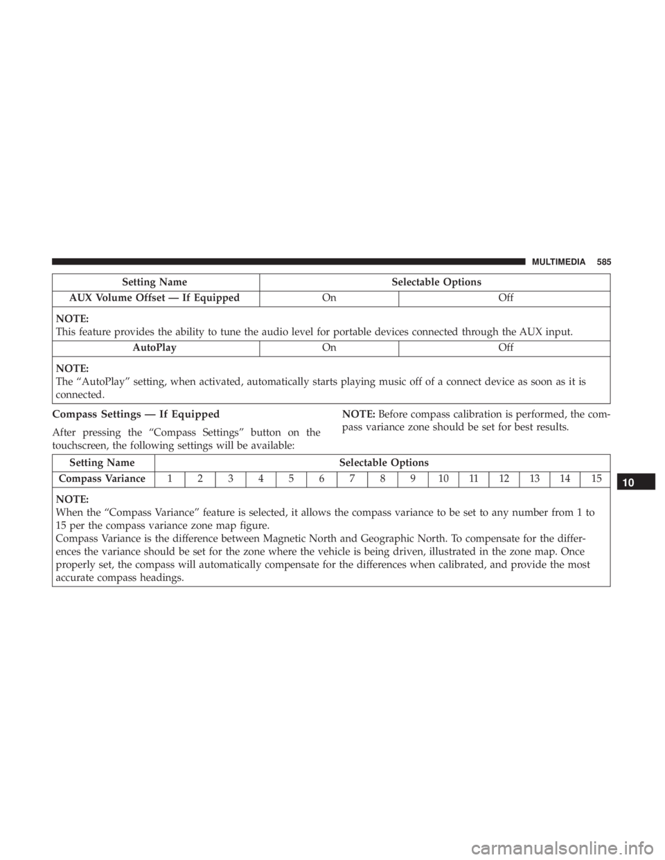
Compass Settings — If Equipped
After pressing the “Compass Settings” button on the
touchscreen, the following settings will be available: NOTE:
Before compass calibration is performed, the com-
pass variance zone should be set for best results.
Setting Name Selectable Options
Compass Variance 1 2 3 4 5 6 7 8 9 10 11 12 13 14 15
NOTE:
When the “Compass Variance” feature is selected, it allows the compass variance to be set to any number from 1 to
15 per the compass variance zone map figure.
Compass Variance is the difference between Magnetic North and Geographic North. To compensate for the differ-
ences the variance should be set for the zone where the vehicle is being driven, illustrated in the zone map. Once
properly set, the compass will automatically compensate for the differences when calibrated, and provide the most
accurate compass headings.
10
MULTIMEDIA 585
Page 612 of 696
Audio
After pressing the “Audio” button on the touchscreen, the
following settings will be available:
Setting NameSelectable Options
Balance/Fade Speaker Icon
NOTE:
When in this display you may adjust the “Balance/Fade” of the audio by pressing and dragging the “Speaker Icon”
toward any location in the box. Equalizer BassMid Treble
NOTE:
When in this display you may adjust the “Bass”, “Mid” and “Treble” settings. Adjust the settings with the “+” and
“–” setting buttons on the touchscreen or by selecting any point on the scale between the “+” and “–” buttons on the
touchscreen. Bass/Mid/Treble also allow you to simply slide your finger up or down to change the setting, as well as
press directly on the desired setting. Speed Adjusted Volume Off12 3
Surround Sound — If Equipped OnOff
AUX Volume Offset — If Equipped +-
NOTE:
This feature provides the ability to tune the audio level for portable devices connected through the AUX input. Auto Play OnOff
610 MULTIMEDIA