Page 446 of 696
Cavity Cartridge FuseBlade FuseDescription
F77A –10 Amp Red RR Entertainment Screen 1 & 2/Media HUB 1 &
2/3rd Row USB Charge Only/2nd Row USB
Charge Only/Vaccum Cleaner SW/3rd Row Re- cline ST SW/LT & RT Stow N Go SW/LT & RT Sliding Door SW Backlight
F77B –10 Amp Red Rain Sensor/Sunroof /CRVMM
F78A –15 Amp Blue Transmission Control Module (TCM)/ E-Shifter
F78B –15 Amp Blue Instrument Cluster
F79 –10 Amp Red ICS/Front And Rear HVAC/ SCCM/ EPB
F80 – – Not Used
F81 – – Not Used
F82 – – Not Used
F83 20 Amp Blue –TT Park Lights — If Equipped
30 Amp Pink –Headlamp Washer Pump — If Equipped
F84 – – Not Used
F85 –20 Amp Yellow Cigar Lighter
F86 – – Not Used
F87 – – Not Used
F88 –20 Amp Yellow Front Heated Seats
F89 –20 Amp Yellow Rear Heated Seats
444 IN CASE OF EMERGENCY
Page 457 of 696

Road Tire Installation
Vehicles Equipped With Wheel Covers
1. Mount the road tire on the axle.
2. To ease the installation process for steel wheels withwheel covers, install two lug nuts on the mounting
studs which are on each side of the valve stem. Install
the lug nuts with the cone shaped end of the nut toward
the wheel. Lightly tighten the lug nuts. 3. Align the valve notch in the wheel cover with the valve
stem on the wheel. Install the cover by hand, snapping
the cover over the two lug nuts. Do not use a hammer or
excessive force to install the cover.
4. Install the remaining lug nuts with the cone shaped end of the nut toward the wheel. Lightly tighten the lug
nuts.
WARNING!
To avoid the risk of forcing the vehicle off the jack, do
not tighten the wheel nuts fully until the vehicle has
been lowered. Failure to follow this warning may
result in serious injury.
5. Lower the vehicle to the ground by turning the jack handle counterclockwise.
6. Finish tightening the lug nuts. Push down on the wrench while at the end of the handle for increased
leverage. Tighten the lug nuts in a star pattern until each
nut has been tightened twice. Refer to “Torque Specifi-
cations” in “Technical Specifications” for proper wheel
lug nut torque. If in doubt about the correct tightness,
have them checked with a torque wrench by an autho-
rized dealer or at a service station.
Tire And Wheel Cover Or Center Cap1 — Valve Stem 4 — Wheel Cover
2 — Valve Notch 5 — Mounting Stud
3 — Wheel Lug Nut
7
IN CASE OF EMERGENCY 455
Page 458 of 696
 check the lug nut torque with atorque wrench to ensure that all lug nuts are properly
seated against the wheel.
Vehicles Without Wheel Covers
1. Mount the road tire on the ax")
7. After 25 miles (40 km) check the lug nut torque with atorque wrench to ensure that all lug nuts are properly
seated against the wheel.
Vehicles Without Wheel Covers
1. Mount the road tire on the axle.
2. Install the remaining lug nuts with the cone shaped endof the nut toward the wheel. Lightly tighten the lug
nuts.
WARNING!
To avoid the risk of forcing the vehicle off the jack, do
not tighten the wheel nuts fully until the vehicle has
been lowered. Failure to follow this warning may
result in serious injury. 3. Lower the vehicle to the ground by turning the jack
handle counterclockwise.
4. Finish tightening the lug nuts. Push down on the wrench while at the end of the handle for increased
leverage. Tighten the lug nuts in a star pattern until each
nut has been tightened twice. Refer to “Torque Specifi-
cations” in the “Technical Specifications” section for
proper wheel lug nut torque. If in doubt about the
correct tightness, have them checked with a torque
wrench by your authorized dealer or at a service station.
5. After 25 miles (40 km) check the lug nut torque with a torque wrench to ensure that all lug nuts are properly
seated against the wheel.
456 IN CASE OF EMERGENCY
Page 491 of 696

SCHEDULED SERVICING
Your vehicle is equipped with an automatic oil change
indicator system. The oil change indicator system will
remind you that it is time to take your vehicle in for
scheduled maintenance.
Based on engine operation conditions, the oil change
indicator message will illuminate. This means that service
is required for your vehicle. Operating conditions such as
frequent short-trips, trailer tow, extremely hot or cold
ambient temperatures will influence when the “Oil Change
Required” message is displayed. Severe Operating Condi-
tions can cause the change oil message to illuminate as
early as 3,500 miles (5,600 km) since last reset. Have your
vehicle serviced as soon as possible, within the next 500
miles (805 km).
Your authorized dealer will reset the oil change indicator
message after completing the scheduled oil change. If a
scheduled oil change is performed by someone other than
your authorized dealer, the message can be reset by
referring to “Instrument Cluster Display” in “Getting To
Know Your Instrument Panel”.NOTE:
Under no circumstances should oil change inter-
vals exceed 10,000 miles (16,000 km), twelve months or 350
hours of engine run time, whichever comes first. The 350
hours of engine run or idle time is generally only a concern
for fleet customers.
Severe Duty All Models
Change Engine Oil at 4,000 miles (6,500 km) or 350 hours of
engine run time if the vehicle is operated in a dusty and off
road environment or is operated predominately at idle or
only very low engine RPM’s. This type of vehicle use is
considered Severe Duty.
Once A Month Or Before A Long Trip:
• Check engine oil level.
• Check windshield washer fluid level.
• Check tire pressure and look for unusual wear or
damage. Rotate tires at the first sign of irregular wear,
even if it occurs before the oil indicator system turns on.
• Check the fluid levels of the coolant reservoir and brake
master cylinder, fill as needed.
• Check function of all interior and exterior lights.
8
SERVICING AND MAINTENANCE 489
Page 517 of 696

Brake Master Cylinder
The fluid in the master cylinder should be checked when
performing under hood services or immediately if the
“Brake Warning Light” is illuminated.
Be sure to clean the top of the master cylinder area before
removing the cap. If necessary, add fluid to bring the fluid
level up to the requirements described on the brake fluid
reservoir. With disc brakes, fluid level can be expected to
fall as the brake pads wear. Brake fluid level should be
checked when pads are replaced. However, low fluid level
may be caused by a leak and a checkup may be needed.
Use only manufacturer’s recommended brake fluid. Refer
to “Fluids And Lubricants” in “Technical Specifications”
for further information.
WARNING!
•Use only manufacturer’s recommended brake fluid.
Refer to “Fluids And Lubricants” in “Technical
Specifications” for further information. Using the
wrong type of brake fluid can severely damage your
brake system and/or impair its performance. The
proper type of brake fluid for your vehicle is also
(Continued)
WARNING! (Continued)
identified on the original factory installed hydraulic
master cylinder reservoir.
• To avoid contamination from foreign matter or mois-
ture, use only new brake fluid or fluid that has been
in a tightly closed container. Keep the master cylin-
der reservoir cap secured at all times. Brake fluid in
a open container absorbs moisture from the air
resulting in a lower boiling point. This may cause it
to boil unexpectedly during hard or prolonged brak-
ing, resulting in sudden brake failure. This could
result in a collision.
• Overfilling the brake fluid reservoir can result in
spilling brake fluid on hot engine parts, causing the
brake fluid to catch fire. Brake fluid can also damage
painted and vinyl surfaces, care should be taken to
avoid its contact with these surfaces.
• Do not allow petroleum based fluid to contaminate
the brake fluid. Brake seal components could be
damaged, causing partial or complete brake failure.
This could result in a collision.
8
SERVICING AND MAINTENANCE 515
Page 520 of 696
 — Metric tire sizing is based on U.S.
design standards. P-Metric tires have the letter “P”
molded into the sidewall preceding the size designation.
Example: P")
Tire MarkingsNOTE:
•P (Passenger) — Metric tire sizing is based on U.S.
design standards. P-Metric tires have the letter “P”
molded into the sidewall preceding the size designation.
Example: P215/65R15 95H.
• European — Metric tire sizing is based on European
design standards. Tires designed to this standard have
the tire size molded into the sidewall beginning with the
section width. The letter �P�is absent from this tire size
designation. Example: 215/65R15 96H.
• LT (Light Truck) — Metric tire sizing is based on U.S.
design standards. The size designation for LT-Metric
tires is the same as for P-Metric tires except for the letters
“LT” that are molded into the sidewall preceding the
size designation. Example: LT235/85R16.
• Temporary spare tires are designed for temporary emer-
gency use only. Temporary high pressure compact spare
tires have the letter “T” or “S” molded into the sidewall
preceding the size designation. Example: T145/80D18
103M.
• High flotation tire sizing is based on U.S. design stan-
dards and it begins with the tire diameter molded into
the sidewall. Example: 31x10.5 R15 LT.
Tire Markings
1 — U.S. DOT Safety
Standards Code (TIN) 4 — Maximum Load
2 — Size Designation 5 — Maximum Pressure
3 — Service Description 6 — Treadwear, Traction
and Temperature Grades
518 SERVICING AND MAINTENANCE
Page 521 of 696
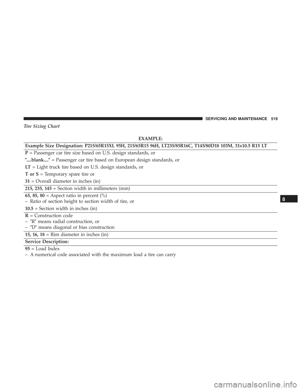
Tire Sizing Chart
EXAMPLE:
Example Size Designation: P215/65R15XL 95H, 215/65R15 96H, LT235/85R16C, T145/80D18 103M, 31x10.5 R15 LT
P = Passenger car tire size based on U.S. design standards, or
�....blank....� = Passenger car tire based on European design standards, or
LT = Light truck tire based on U.S. design standards, or
TorS= Temporary spare tire or
31 = Overall diameter in inches (in)
215, 235, 145 = Section width in millimeters (mm)
65, 85, 80 = Aspect ratio in percent (%)
–Ratio of section height to section width of tire, or
10.5 = Section width in inches (in)
R = Construction code
–�R� means radial construction, or
–�D� means diagonal or bias construction
15, 16, 18 = Rim diameter in inches (in)
Service Description:
95 = Load Index
–A numerical code associated with the maximum load a tire can carry
8
SERVICING AND MAINTENANCE 519
Page 522 of 696
EXAMPLE:
H = Speed Symbol
–A symbol indicating the range of speeds at which a tire can carry a load corresponding to its load index under cer-
tain operating conditions
–The maximum speed corresponding to the speed symbol should only be achieved under specified operating condi-
tions (i.e., tire pressure, vehicle loading, road conditions, and posted speed limits)
Load Identification:
Absence of the following load identification symbols on the sidewall of the tire indicates a Standard Load (SL) tire:
• XL = Extra load (or reinforced) tire, or
• LL = Light load tire or
• C, D, E, F, G = Load range associated with the maximum load a tire can carry at a specified pressure
Maximum Load – Maximum load indicates the maximum load this tire is designed to carry
Maximum Pressure – Maximum pressure indicates the maximum permissible cold tire inflation pressure for this tire
520 SERVICING AND MAINTENANCE