Page 358 of 614

WARNING!
Drivers must be careful when performing parallel or
perpendicular parking maneuvers even when using
the ParkSense Active Park Assist system. Always
check carefully behind and in front of your vehicle,
look behind and in front of you, and be sure to check
for pedestrians, animals, other vehicles, obstructions,
and blind spots before backing up and moving for-
ward. You are responsible for safety and must continue
to pay attention to your surroundings. Failure to do so
can result in serious injury or death.
CAUTION!
•The ParkSense Active Park Assist system is only a
parking aid and it is unable to recognize every
obstacle, including small obstacles. Parking curbs
might be temporarily detected or not detected at all.
Obstacles located above or below the sensors will
not be detected when they are in close proximity.
• The vehicle must be driven slowly when using the
ParkSense Active Park Assist system in order to be
able to stop in time when an obstacle is detected. It is
(Continued)
CAUTION! (Continued)
recommended that the driver looks over his/her
shoulder when using the ParkSense Active Park
Assist system.
LANESENSE — IF EQUIPPED
LaneSense Operation
The LaneSense system is operational at speeds above
37 mph (60 km/h) and below 105 mph (169 km/h). It uses
a forward looking camera to detect lane markings and
measure vehicle position within the lane boundaries.
When both lane markings are detected and the driver
unintentionally drifts out of the lane (no turn signal
applied), the LaneSense system provides a haptic warning
in the form of torque applied to the steering wheel to
prompt the driver to remain within the lane boundaries.
The LaneSense system will also provide a visual warning
through the instrument cluster display to prompt the
driver to remain within the lane boundaries.
The driver may manually override the haptic warning by
applying torque into the steering wheel at any time.
356 STARTING AND OPERATING
Page 359 of 614

When only a single lane marking is detected and the driver
unintentionally drifts across that lane marking (no turn
signal applied), the LaneSense system provides a visual
warning through the instrument cluster display to prompt
the driver to remain within the lane. When only a single
lane marking is detected, a haptic (torque) warning will not
be provided.
NOTE:When operating conditions have been met, the
LaneSense system will monitor if the driver ’s hands are on
the steering wheel and provides an audible and visual
warning to the driver when the driver ’s hands are not
detected on the steering wheel. The system will cancel if
the driver does not return their hands to the wheel.
Turning LaneSense On Or Off
The LaneSense button is located on the switch
panel below the Uconnect display.
To turn the LaneSense system on, push the LaneSense
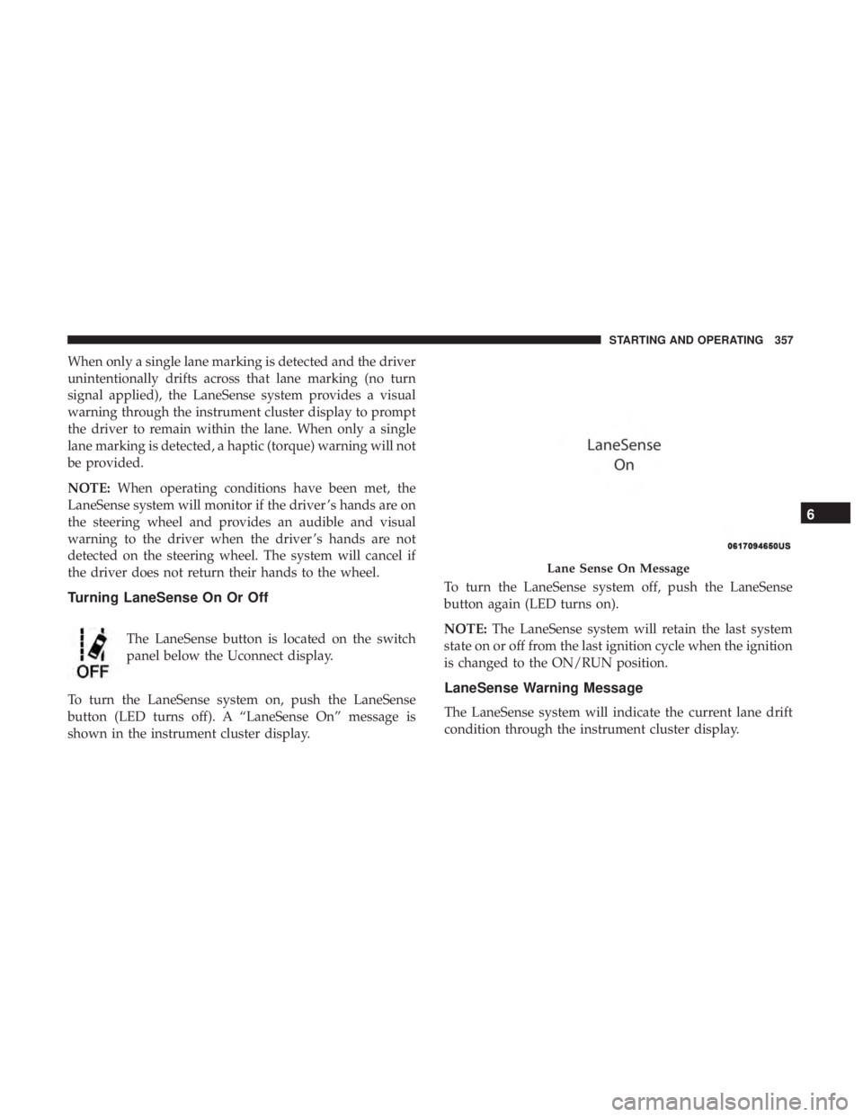
button (LED turns off). A “LaneSense On” message is
shown in the instrument cluster display. To turn the LaneSense system off, push the LaneSense
button again (LED turns on).
NOTE:
The LaneSense system will retain the last system
state on or off from the last ignition cycle when the ignition
is changed to the ON/RUN position.
LaneSense Warning Message
The LaneSense system will indicate the current lane drift
condition through the instrument cluster display.
Lane Sense On Message
6
STARTING AND OPERATING 357
Page 360 of 614

Instrument Cluster Display
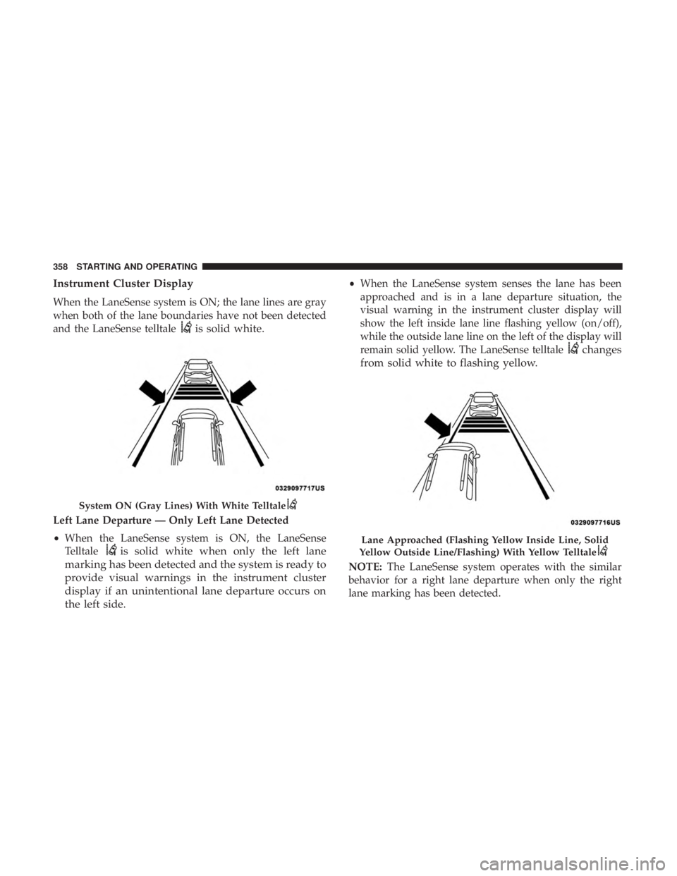
When the LaneSense system is ON; the lane lines are gray
when both of the lane boundaries have not been detected
and the LaneSense telltale
is solid white.
Left Lane Departure — Only Left Lane Detected
•When the LaneSense system is ON, the LaneSense
Telltale
is solid white when only the left lane
marking has been detected and the system is ready to
provide visual warnings in the instrument cluster
display if an unintentional lane departure occurs on
the left side.
• When the LaneSense system senses the lane has been
approached and is in a lane departure situation, the
visual warning in the instrument cluster display will
show the left inside lane line flashing yellow (on/off),
while the outside lane line on the left of the display will
remain solid yellow. The LaneSense telltale
changes
from solid white to flashing yellow.
NOTE: The LaneSense system operates with the similar
behavior for a right lane departure when only the right
lane marking has been detected.
System ON (Gray Lines) With White Telltale
Lane Approached (Flashing Yellow Inside Line, Solid
Yellow Outside Line/Flashing) With Yellow Telltale
358 STARTING AND OPERATING
Page 361 of 614

Left Lane Departure — Both Lane Lines Detected
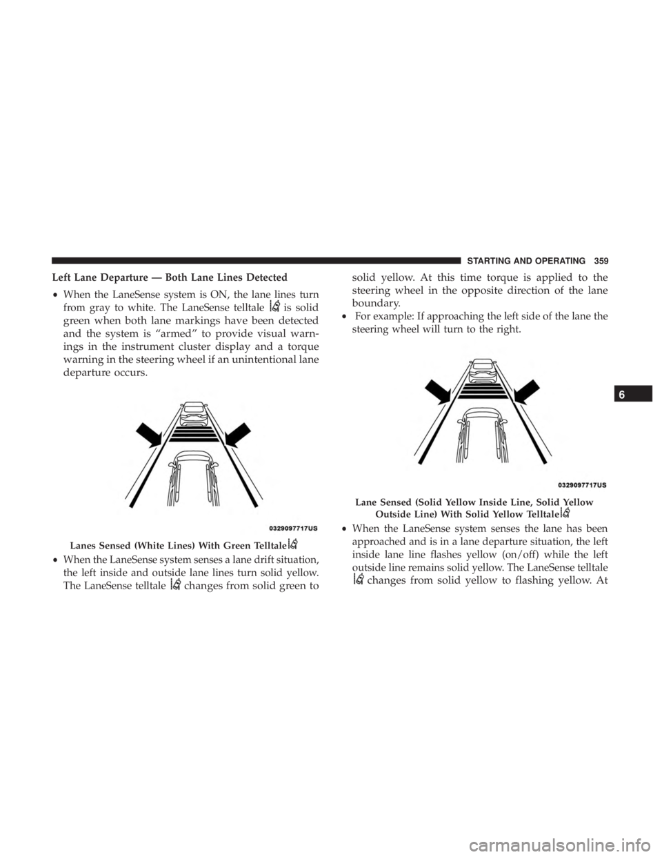
•When the LaneSense system is ON, the lane lines turn
from gray to white. The LaneSense telltale
is solid
green when both lane markings have been detected
and the system is “armed” to provide visual warn-
ings in the instrument cluster display and a torque
warning in the steering wheel if an unintentional lane
departure occurs.
• When the LaneSense system senses a lane drift situation,
the left inside and outside lane lines turn solid yellow.
The LaneSense telltale
changes from solid green to solid yellow. At this time torque is applied to the
steering wheel in the opposite direction of the lane
boundary.
•
For example: If approaching the left side of the lane the
steering wheel will turn to the right.
• When the LaneSense system senses the lane has been
approached and is in a lane departure situation, the left
inside lane line flashes yellow (on/off) while the left
outside line remains solid yellow. The LaneSense telltale
changes from solid yellow to flashing yellow. At
Lanes Sensed (White Lines) With Green Telltale
Lane Sensed (Solid Yellow Inside Line, Solid Yellow
Outside Line) With Solid Yellow Telltale
6
STARTING AND OPERATING 359
Page 369 of 614
REFUELING THE VEHICLE
1. Put the vehicle in the PARK postion.
2. Press the fuel filler door release button (located in thedriver’s door in the upper map pocket).
3. The button press will initiate a sequence of events to depressurize the fuel system. A message will display in
the cluster letting you know when the vehicle is ready to
be fueled. NOTE:
•After pushing the release button you will have 20 min-
utes to fuel the vehicle, beyond 20 minutes you will
need to press the release button again.
• The fuel door could take up to 15 seconds to open. It
may take longer to open in some situations, such as
high ambient temperatures.
• If you hear a hissing sound when the nozzle is inserted
into the filler pipe, wait to begin fueling the vehicle
until after the hissing sound stops.
Fuel Filler Door Release Switch
Instrument Cluster Message
6
STARTING AND OPERATING 367
Page 386 of 614
BULB REPLACEMENT
Replacement Bulbs
Interior Bulbs
LampsBulb Number
Center & Rear Dome Lamp LED (Serviced At Authorized Dealer)
Center & Rear Reading Lamps LED (Serviced At Authorized Dealer)
Front Door Courtesy Lamp LED (Serviced At Authorized Dealer)
Front Header Reading Lamps – If Equipped LED (Serviced At Authorized Dealer)
Instrument Cluster Lamps LED (Serviced At Authorized Dealer)
Liftgate Lamp(s) LED (Serviced At Authorized Dealer)
Overhead Console Reading Lamps LED (Serviced At Authorized Dealer)
Removable Console Lamp – If Equipped LED (Serviced At Authorized Dealer)
Visor Vanity Lamps 6501966
384 IN CASE OF EMERGENCY
Page 398 of 614
CavityCartridge Fuse Blade FuseDescription
F56A –10 Amp RedFRT. & RR HVAC CTRL/
OCM / ESL
F56B – B. EPS / ESC - Electric Sta-
bility Ctr
F57 –20 Amp Yellow PIM - Main Power Supply
F58 ––Not Used
F59 ––Not Used
F60 –20 Amp Yellow Rear Cargo APO
F61 ––Not Used
F62 –20 Amp Yellow PIM-Main PWR Supply
F63 –5 Amp TanHV Elect Coolant HTR En-
able
F64 ––Not Used
F65 ––Not Used
F66 –15 Amp Blue Instrument Panel Cluster
(IPC) / SGW
F67 –10 Amp Red HALF / PTS / Drivers As-
sist System Module(DASM)
F68 ––Not Used
396 IN CASE OF EMERGENCY
Page 400 of 614
CavityCartridge Fuse Blade FuseDescription
F77A –10 Amp Red Rear Entertainment / Me-
dia HUB / 3RD & 2ND
Row USB CHRG / Vacuum Cleaner SW Backlight /3RD Row Recliner SW
Backlight / 2ND Row Stow N Go SW Backlight /
LT&RT Sliding Door Back- light
F77B – B. Sunroof / Rain sensor /
Rear View Mirror / PIM
F78A –15 Amp Blue Transmission control Mod-
ule (TCM) / E-Shifter /ESM
F78B – Instrument Cluster
F79A –10 Amp Red ICS / Frt & Rr HVAC /
EPB Sw / SCCM
F79B – Not Used
F80 –5 Amp Tan OBCM
F81 –5 Amp Tan APM
F82 ––Not Used
F83 30 Amp Pink –Trans Oil Pump 1
398 IN CASE OF EMERGENCY