Page 161 of 260

Engagement/Disengagement
To turn the system off, push the Park
Sensors System switch located to the
left of the headlight switch. The indicator
light within the switch will illuminate
when the system is turned off. Pushing
the switch a second time will turn the
system back on, and the indicator light
will turn off.
The indicator light within the Park
Sensors System switch will also be on in
case of system failure. If the switch is
pushed with a system failure, the
indicator light will flash for
approximately five seconds. The light will
then stay on constantly.
Note:When the ignition is cycled to ON,
the Park Sensors system keeps the last
state when the engine was stopped
(activated or deactivated) in its memory. System Activation/Deactivation
When the REVERSE gear is engaged and
the system is on, the front and rear
sensors are activated. If the vehicle
moves from REVERSE to a forward gear,
the rear sensors are deactivated, while
the front sensors remain active until the
speed of 9 mph (15 km/h) is exceeded.
Note:
In certain operating conditions, the
system could start detecting an obstacle
only after the vehicle has moved slightly
(a few inches).
Acoustic Signal
In the presence of an obstacle at the
front or the rear of the vehicle, an
acoustic signal with variable frequency
will sound:
The acoustic signal increases in
frequency as the distance between the
vehicle and the obstacle decreases.
The acoustic signal becomes
continuous when the distance between
the vehicle and the obstacle is less than
11 inches (30 cm), and stops if the
distance increases.
The acoustic signal is constant if the
distance between the vehicle and the
obstacle is unchanged.
Note: If the sensors detect several front
and rear obstacles, the closest obstacle
is considered. An intermittent signal will
sound if the obstacles are at the same
distance (front and rear). When the system emits an acoustic
signal, the volume of the Information and
Entertainment System, if activated, is
automatically lowered.
Indication On Display
The driver can select the type of warning
they would like to be displayed through
the Information and Entertainment
System. To access the function on the
main menu, select in the following order:
1. “Settings.”
2. “Driver Assistance.”
3. “ParkSense.”
4. “Mode.”
5. “Sound-Display.”
Visual Indications
The system indicates the presence of an
obstacle by displaying a single red arc in
the detected areas, in relation to the
distance of the object and the position of
the vehicle.
If the obstacle is detected in the front or
rear central area, a single red arc will be
displayed as the obstacle approaches,
first constant, then flashing, in addition
to an acoustic signal.
If the obstacle is detected in the front or
rear left and/or right area, a single red
flashing arc will be shown in the
corresponding area on the display and
the system will emit an acoustic signal,
either at frequent intervals or constantly.
07176S0052EMPark Sensors System On/Off Switch
159
Page 162 of 260

If several obstacles are detected
simultaneously in the front and rear area,
the display will show all of them,
regardless of the area in which they were
detected.
In general, the vehicle is closer to the
obstacle when a single or several flashing
arcs are shown on the display and the
acoustic signal becomes continuous.
It is not possible to exit from the display
screen while the vehicle is in REVERSE.
Fault Indication
Parking sensor faults, if any, will be
indicated by a message on the display on
the instrument cluster. Refer to "Warning
Lights And Messages" in "Getting To
Know Your Instrument Panel" for further
information.
Messages On The Display
In case of system failure, a dedicated
message appears on the instrument
cluster for about five seconds.
Cleaning The Front Or Rear Sensors:
If the display shows a message requiring
the sensors to be cleaned, make sure that
the outer surface and the underside of
the front and rear bumpers are free of
debris (e.g. snow, mud, ice, etc.). Once
these areas are clear, cycle the ignition to
STOP. Then, return it to ON mode. If the
message is still displayed, contact you
authorized dealer.
Audio System Not Available : If the
display shows a message that the audio
system is not available, it means that the
acoustic signal will be emitted by the
instrument panel, and not through the
vehicles speakers.
Note: Some conditions may influence
the performance of the Park Sensors
System:
Reduced sensor sensitivity could be
due to the presence of ice, snow, mud, or
thick paint on the surface of the sensor.
The sensors may detect a false
obstacle (echo interference) due to
mechanical interference, for example
when washing the vehicle or in extreme
weather.
The signals sent by the sensors can
be altered by the presence of ultrasonic
systems (e.g. pneumatic brake systems
of trucks or pneumatic drills) near the
vehicle.
System performance can be
influenced by the position of the
sensors. For example, due to a change in
the ride setting (caused by wear to the
shock absorbers or suspension), by
changing tires, overloading the vehicle or
operations that require the vehicle to be
lowered.
Be sure not to place bumper stickers
or other adhesives over the sensors as
this will affect system performance.
Warning!
Drivers must be careful when backing up
even when using the Parking Sensor system.
Always check carefully behind your vehicle,
and be sure to check for pedestrians,
animals, other vehicles, obstructions, or
blind spots before backing up. You are
responsible for the safety of your
surroundings and must continue to pay
attention while backing up. Failure to do so
can result in serious injury or death.
Caution!
The Parking Sensor system is only a
parking aid and it is unable to recognize
every obstacle, including small obstacles.
Parking curbs might be temporarily detected
or not detected at all. Obstacles located
above or below the sensors will not be
detected when they are in close proximity
The vehicle must be driven slowly when
using the Parking Sensor system in order to
be able to stop in time when an obstacle is
detected. It is recommended that the driver
looks over his/her shoulder when using the
Parking Sensor system.
160
STARTING AND OPERATING
Page 163 of 260
 SYSTEM — IF EQUIPPED
Description
The Lane Departure Warning system uses
a forward looking camera located on the
windshield to detect lane markings and
measure vehicle po")
LANE DEPARTURE WARNING
(LDW) SYSTEM — IF EQUIPPED
Description
The Lane Departure Warning system uses
a forward looking camera located on the
windshield to detect lane markings and
measure vehicle position within the lane
boundaries.
When one or both lane limits are detected
and the vehicle passes over one without
an activated turn signal, the system emits
a visual as well as an audible signal.
If the vehicle continues to go beyond the
line of the lane without any intervention
from the driver, the surpassed line will
light up on the display (left or right) to
urge the driver to bring the vehicle back
into the limits of the lane.
Caution!
Do not tamper with nor operate on the
camera. Do not close the openings in the
aesthetic cover located under the interior
rear view mirror. In the event of a failure of
the camera, contact your authorized dealer.
The camera may have limited or absent
operation due to weather conditions such
as: heavy rain, hail, thick fog, heavy snow,
formation of ice layers on the windshield.
Camera operation may also be
compromised by the presence of dust,
condensation, dirt or ice on the windshield, by traffic conditions (e.g. vehicles that are
driving not aligned with yours, vehicle
driving in a transverse or opposite way on
the same lane, bend with a small radius of
curvature), by road surface conditions and
by driving conditions (e.g. off-road driving).
Make sure the windshield is always clean.
Use specific detergents and clean cloths to
avoid scratching the windshield. The camera
operation may also be limited or absent in
some driving, traffic and road surface
conditions.
If the windshield must be replaced due to
scratches, chipping or breakage, contact
exclusively your authorized dealer. Do not
replace the windshield on your own. It is
advisable to replace the windshield if it is
damaged in the area of the camera.
System Activation/Deactivation
The system is activated/deactivated by
pushing the button located on the end of
the multifunction lever. Note:
When the engine is started, the
system maintains the operating mode
that was selected when it was turned
OFF.
Activation Conditions
Once turned on, the system becomes
active only if the following conditions are
met:
The vehicle speed is above 37 mph
(60 km/h).
The lane limit lines are visible at least
on one side.
There are suitable visibility conditions.
The road is straight or with wide radius
bends.
A suitable distance is kept from the
vehicle in front.
The turn signal is not active.
07226S0001EMLane Departure Warning System Activation/Deactivation Button
161
Page 164 of 260

Symbols And Messages On The Display
The Lane Departure Warning system
advises the driver when the vehicle
leaves the driving lane by showing
symbols and messages on the instrument
cluster display.
When the system is active and the lane
limits have not been detected, the display
shows a grey vehicle icon with two grey
lines.Exiting A Lane With Detection Of A
Single Limit
When the system is active and only, for
example, the left lane limit has been
detected, the detected lane illuminates in
white on the display; the system is ready
to provide visual warnings on the display
in the event of unintentional exiting of
the lane (turn signal not activated) to the
left.
When the system detects that the vehicle
has approached the lane line and is about
to pass it, the left line on the display
illuminates in yellow.
The system operates in the same way,
but mirrored, in the event of exiting the
right lane when only the right lane limit
has been detected.
Exiting A Lane With Detection Of Both
Limits
When the system is active, both lane lines
on the display illuminate in white to
indicate the successful detection of both
limits.
07226S0002EMVehicle Changing Lanes
07226S0007EMLane Limits Not Detected
07226S0003EMLeft Lane Limit Detected
07226S0004EMLeft Lane Limit Approached
07226S0005EMBoth Lane Limits Detected
162
STARTING AND OPERATING
Page 165 of 260
.
As the Lane Departure Warning system
detects t")
When lane limits are detected, the
system is ready to provide indications in
case the driver unintentionally leaves the
lane (turn signal not activated).
As the Lane Departure Warning system
detects the lane limits while the vehicle is
in motion, it will adjust the display
accordingly (from white to yellow and
vice versa, and increase their thickness).
If a line is crossed, the driver is alerted by
an audible signal as well as the visual
indication in the instrument cluster. The
signal is emitted through the speakers on
the side of the lane limit which is being
crossed (eg. if the vehicle is exceeding
the left line of the lane, the audible signal
will come from the speakers on the left of
the vehicle).
Changing The System Settings
The system's sensitivity can be set
through the Information and
Entertainment System. Sensitivity “High”
or “Low” can be selected.To access the function, from the main
menu select the following in order:
1. “Settings.”
2. “Safety.”
3. “Lane Departure Warning.”
4. “Sensitivity.”
Limited Operation Warning
If a message appears on the display, a
condition limiting the Lane Departure
Warning system operation may have
occurred. This could be an obstruction of
the camera view, or a fault in the system.
If an obstruction is detected, clean the
area of the windshield by the interior rear
view mirror.
Although the vehicle can still be driven in
normal conditions, the system may not
function properly.
When the conditions limiting the system
are corrected, it will go back to normal
operation. Should a fault persist, contact
your authorized dealer.
System Failure Warning
If the system turns off and the warning
light
appears on the display, it means
that there is a system fault.
In this case, it is still possible to drive the
vehicle, but you are advised to contact
your authorized dealer as soon as
possible.
REAR BACK-UP CAMERA /
DYNAMIC GRIDLINES
Description
The Rear Back-Up Camera is located just
under the vehicle’s trunk lid, above the
rear license plate.
When the vehicle is in REVERSE, the
Information and Entertainment System
display will show the area behind the
vehicle, as seen by the Rear Back-Up
Camera, along with a warning message.
07226S0006EMRight Lane Limit Approached
07186S0001EMRear Back-Up Camera Location
07186S000218Rear Back-Up Camera Display163
Page 166 of 260

Rear Back-Up Camera Features
To activate the Rear Back-Up Camera
features, select “Settings” from the
Main Menu of the Information and
Entertainment System.
Under “Driver Assistance” the following
features can be selected:
View
Camera Delay
Camera Guidelines
Selecting “View” will activate the camera
view on the display.
Selecting “Camera Delay” will allow the
camera view to remain on the display
shortly after the vehicle is no longer in
REVERSE, followed by the previously
active screen.
Selecting “Camera Guidelines” will
activate the display of the dynamic
guidelines that indicate the route of the
vehicle while in REVERSE.
Warning!
Drivers must be careful when backing up
even when using the Rear Back-Up Camera.
Always check carefully behind your vehicle,
and be sure to check for pedestrians,
animals, other vehicles, obstructions, or
blind spots before backing up. You are
responsible for the safety of your
surroundings and must continue to pay
attention while backing up. Failure to do so
can result in serious injury or death.
Caution!
To avoid vehicle damage, Rear Back-Up
Camera should only be used as a parking
aid. The Rear Back-Up Camera is unable to
view every obstacle or object in your drive
path.
To avoid vehicle damage, the vehicle
must be driven slowly when using the Rear
Back-Up Camera to be able to stop in time
when an obstacle is seen. It is recommended
that the driver look frequently over his/her
shoulder when using the Rear Back-Up
Camera.
Symbols And Messages On The Display
Indications On The Display
Through the Information and
Entertainment System settings, by
activating the "Camera Guidelines"
feature, guidelines can be seen on the
rear camera display. If activated, the
guidelines are positioned on the image to
highlight the width of the vehicle and the
expected reverse path based on the
steering wheel position.
A superimposed central line indicates the
center of the vehicle to assist in rear
parking maneuvers. The various colored
areas indicate the distance from the rear
of the vehicle. The table below shows the approximate
distances for each area:
Area
Distance from the
rear of the vehicle
Red 0–11.8
inches
(0–30 cm)
Yellow 11.8 inches to 3.3 feet
(30 cm–1 m)
Green 3.3 feet or more
(1mormore)
Messages On The Display
If the trunk lid is lifted, the camera will
not detect any obstacle behind the
vehicle. The display will show a dedicated
warning message.
Make sure the trunk lid is closed by
pushing next to the lock until it clicks.
Important Notes
Ice, snow or mud on the surface of the
camera may reduce its sensitivity. It is
important to keep the camera surface
clean, and free from debris.
When parking, be aware of obstacles
that may be above or under the camera
range.
164
STARTING AND OPERATING
Page 167 of 260

REFUELING THE VEHICLE
Refueling The Vehicle
Before refueling, make sure that the fuel
type is correct.
Also, stop the engine before refueling.
Note:An inefficient catalytic converter
leads to harmful exhaust emissions, thus
contributing to air pollution.
Caution!
Never introduce leaded fuel to the tank,
even in small amounts in an emergency, as
this would damage the catalytic converter
beyond repair.
Refueling Capacity
To ensure that you fill the tank
completely, top off twice after the first
click of the fuel nozzle.
Further top-off could cause faults in the
fuel feeding system.
Refueling Procedure
The fuel filler door is unlocked when the
central door locking system is unlocked.
It is automatically locked when the
central locking system is applied. Opening The Fuel Filler Door
To refuel proceed as follows:
1. Open fuel filler door by pressing on
the point shown by the arrow.
2. Remove the fuel filler cap.
3. Insert the fuel nozzle fully into the
filler pipe.
4. When the fuel nozzle “clicks” or shuts
off, before removing the nozzle, wait for
at least 10 seconds in order for the fuel
to flow inside the tank.
5. Remove the fuel filler nozzle, tighten
the gas cap about ¼ turn until you hear
one click. This is an indication that cap is
properly tightened.
The label indicates the fuel type
(UNLEADED FUEL = gasoline).
Emergency Fuel Door Opening
In the event of an emergency the fuel
filler door can be opened by operating
from inside the trunk.
Proceed as follows:
1. Open the trunk and locate the
emergency fuel filler release cap on the
inside lining.
2. Open the cap, and pull the cord inside
to unlock the fuel filler door.
3. Open the fuel filler door by pressing
on it (see the previous instructions).
07206S0001EMFuel Door
07206S0002EMFuel Door Label
165
Page 168 of 260

Warning!
Never have any smoking materials lit in or
near the vehicle when the fuel door is open
or the tank is being filled.
Never add fuel when the engine is running.
This is in violation of most state and federal
fire regulations and may cause the MIL to
turn on.
A fire may result if gasoline is pumped
into a portable container that is inside of a
vehicle. You could be burned. Always place
gas containers on the ground while filling.
Note: If the filler compartment is
washed with a pressure washer, keep it at
a distance of at least 8 inches (20 cm).
VEHICLE LOADING
Certification Label
As required by National Highway Traffic
Safety Administration regulations, your
vehicle has a certification label affixed to
the driver's side door or pillar.
This label contains the month and year of
manufacture, Gross Vehicle Weight
Rating (GVWR), Gross Axle Weight
Rating (GAWR) front and rear, and
Vehicle Identification Number (VIN).
A Month-Day-Hour (MDH) number is
included on this label and indicates the
Month, Day and Hour of manufacture.
The bar code that appears on the bottom
of the label is your VIN.
Gross Vehicle Weight Rating
(GVWR)
The GVWR is the total permissible
weight of your vehicle including driver,
passengers, vehicle, options and cargo.
The label also specifies maximum
capacities of front and rear axle systems
(GAWR). Total load must be limited so
GVWR and front and rear GAWR are not
exceeded.
Payload
The payload of a vehicle is defined as the
allowable load weight a truck can carry,
including the weight of the driver, all
passengers, options and cargo.
Gross Axle Weight Rating (GAWR)
The GAWR is the maximum permissible
load on the front and rear axles. The load
must be distributed in the cargo area so
that the GAWR of each axle is not
exceeded.
Each axle GAWR is determined by the
components in the system with the
lowest load carrying capacity (axle,
springs, tires or wheels). Heavier axles or
suspension components sometimes
specified by purchasers for increased
durability does not necessarily increase
the vehicle's GVWR.
Tire Size
The tire size on the Vehicle Certification
Label represents the actual tire size on
your vehicle. Replacement tires must be
equal to the load capacity of this tire size.
Rim Size
This is the rim size that is appropriate for
the tire size listed.
Inflation Pressure
This is the cold tire inflation pressure for
your vehicle for all loading conditions up
to full GAWR.
166
STARTING AND OPERATING
 1
1 2
2 3
3 4
4 5
5 6
6 7
7 8
8 9
9 10
10 11
11 12
12 13
13 14
14 15
15 16
16 17
17 18
18 19
19 20
20 21
21 22
22 23
23 24
24 25
25 26
26 27
27 28
28 29
29 30
30 31
31 32
32 33
33 34
34 35
35 36
36 37
37 38
38 39
39 40
40 41
41 42
42 43
43 44
44 45
45 46
46 47
47 48
48 49
49 50
50 51
51 52
52 53
53 54
54 55
55 56
56 57
57 58
58 59
59 60
60 61
61 62
62 63
63 64
64 65
65 66
66 67
67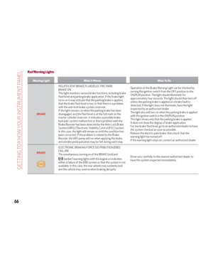 68
68 69
69 70
70 71
71 72
72 73
73 74
74 75
75 76
76 77
77 78
78 79
79 80
80 81
81 82
82 83
83 84
84 85
85 86
86 87
87 88
88 89
89 90
90 91
91 92
92 93
93 94
94 95
95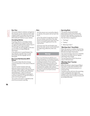 96
96 97
97 98
98 99
99 100
100 101
101 102
102 103
103 104
104 105
105 106
106 107
107 108
108 109
109 110
110 111
111 112
112 113
113 114
114 115
115 116
116 117
117 118
118 119
119 120
120 121
121 122
122 123
123 124
124 125
125 126
126 127
127 128
128 129
129 130
130 131
131 132
132 133
133 134
134 135
135 136
136 137
137 138
138 139
139 140
140 141
141 142
142 143
143 144
144 145
145 146
146 147
147 148
148 149
149 150
150 151
151 152
152 153
153 154
154 155
155 156
156 157
157 158
158 159
159 160
160 161
161 162
162 163
163 164
164 165
165 166
166 167
167 168
168 169
169 170
170 171
171 172
172 173
173 174
174 175
175 176
176 177
177 178
178 179
179 180
180 181
181 182
182 183
183 184
184 185
185 186
186 187
187 188
188 189
189 190
190 191
191 192
192 193
193 194
194 195
195 196
196 197
197 198
198 199
199 200
200 201
201 202
202 203
203 204
204 205
205 206
206 207
207 208
208 209
209 210
210 211
211 212
212 213
213 214
214 215
215 216
216 217
217 218
218 219
219 220
220 221
221 222
222 223
223 224
224 225
225 226
226 227
227 228
228 229
229 230
230 231
231 232
232 233
233 234
234 235
235 236
236 237
237 238
238 239
239 240
240 241
241 242
242 243
243 244
244 245
245 246
246 247
247 248
248 249
249 250
250 251
251 252
252 253
253 254
254 255
255 256
256 257
257 258
258 259
259