Page 97 of 192
WARNING
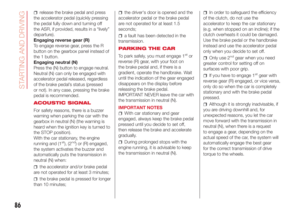
23)Halogen bulbs must be handled holding the metal part only. Touching the transparent part of the bulb with your fingers may reduce the
intensity of the emitted light and even reduce the lifespan of the bulb. In the event of accidental contact, wipe the bulb with a cloth moistened
with alcohol and let the bulb dry.
24)Where possible, it is advisable to have bulbs changed at an Abarth Dealership. The correct operation and direction of the exterior lights
are absolutely essential for the safety of the car and of compliance with the law.
95
Page 98 of 192

REPLACING AN
EXTERIOR BULB
For the type of bulb and power rating,
see paragraph "Replacing a bulb".
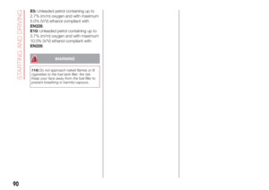
FRONT LIGHT CLUSTERS
The front light clusters contain side
lights, dipped headlights, main beam
headlights and direction indicator bulbs.
Access to the direction indicator
bulbs
Working from the engine compartment,
remove the rubber cap 1 fig. 82.
Access to the main beam headlight
bulbs
Rotate the cap 2 fig. 82 anticlockwise.Access to the daytime running light
(DRL) and main beam headlight
bulbs
Completely steer the wheels and open
guard door 3 fig. 83 (on the wheel
arch at the level of the lights) then
remove the rubber cap 4 fig. 83.
DIRECTION INDICATORS
Front
To replace the bulb, proceed as follows:
turn the protection cap 1 fig. 82
anticlockwise and remove it;
turn the bulb holder 1 fig. 84
anticlockwise and remove it;
remove the pressure-fitted bulb and
replace it;
refit the bulb holder 1 by turning it
clockwise and locking it correctly;
insert the protection cap and turn it
clockwise.Side
IMPORTANT The intervention must be
carried out taking all precautions
necessary to avoid damaging the
bodywork (use a sufficiently rigid and
appropriately thick plastic card).
To replace the bulb, proceed as follows:
apply leverage at the point indicated
by the arrows 1 and 2, in such a way
as to compress the fixing clip and
remove the light fig. 85
1
2
82AB0A0309C
3
4
83AB0A0089C
84AB0A0361C
85AB0A0310C
96
IN AN EMERGENCY
Page 99 of 192

turn the bulb holder anticlockwise,
extract the press-fitted bulb and
replace it;
refit the bulb holder in the lens, then
position the light, ensuring that the
fastening clip clicks into place.
DIPPED HEADLIGHTS
To replace the bulb, proceed as follows:
turn the protection cap 2 fig. 82
anticlockwise and remove it;
disconnect the connector 1 fig. 86
and release the bulb holder;
extract the bulb and replace it;
refit the bulb in its seat and
reconnect the connector;
refit the protection cap in its housing
and turn clockwise.
117)
MAIN BEAM HEADLIGHTS
To replace the bulb, proceed as
follows:
remove the protective rubber cap
mentioned above;
release the two bulb holding clips 1
fig. 87;
extract the bulb and replace it;
fit the new bulb, making the outline
of the metallic part coincide with the
grooves on the reflector, then reattach
the bulb holding clips;
refit the rubber cap.
SIDE LIGHTS/DAYTIME
RUNNING LIGHTS
To replace the bulb, proceed as follows:
remove the protective rubber cap
mentioned above;
turn the bulb holder 2 fig. 87
anticlockwise and remove it;
remove the pressure-fitted bulb and
replace it;
refit the bulb holder 2 by turning it
clockwise and locking it correctly;
refit the rubber cap.
FRONT FOG LIGHTS
(where provided)
For replacing these bulbs, contact an
Abarth Dealership.
REAR LIGHT CLUSTERS
To replace the bulb proceed as follows:
open the tailgate;
unscrew the two fastening screws 1
fig. 88 and extract the light cluster
axially without rotating it;
remove the bulb holder from its
housing releasing it from the locking
tabs 2;
extract the bulbs by pushing them
slightly and turning them anticlockwise.
1
86AB0A0311C
2
1
87AB0A0093C
21
1
22
22
2
88AB0A0313C
97
Page 100 of 192

The bulbs are arranged as follows fig.
89:
1: side / brake light;
2: direction indicators.
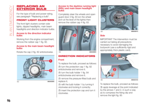
REVERSING LIGHT/REAR
FOG LIGHT
For bulb replacement, contact an
Abarth Dealership.
THIRD BRAKE LIGHTS
To replace the bulb proceed as follows:
remove the two guard caps and
unscrew the two fastening screws 1 fig.
90;
remove the assembly;
disconnect the electrical connector
2 fig. 91;
press the retaining device 3 fig. 91
and open the bulb holder;
remove the press-fitted bulb to be
replaced and replace it;
close the bulb holder making sure
the retaining device is correctly locked;
screw in the two fastening screws
and reinstall the guard caps.
NUMBER PLATE LIGHTS
To replace the bulbs, proceed as
follows:
apply pressure to the point shown
by the arrow fig. 92 and remove the
lens;
change the bulb, releasing it from
the side contacts;
fit the new bulb and make sure that
it is correctly clamped between the
contacts;
then refit the lens.
WARNING
117)Due to the high power supply
voltage, gas discharge bulbs (Xenon)
should only be replaced by specialised
personnel: danger of death! Contact
an Abarth Dealership.
1
2
89AB0A0314C
11
90AB0A0097C
91AB0A0098C
92AB0A0099C
98
IN AN EMERGENCY
Page 101 of 192

REPLACING FUSES
GENERAL INFORMATION
Fuses protect the electrical system:
they intervene (blow) in the event of a
failure or improper action on the
system.
118) 119) 120) 121) 122) 123)
To facilitate fuse replacement, use the
pliers hooked inside the fuse box lid on
the dashboard left-hand side.
Refer to the tables on the following
pages to identify the protective fuse.
FUSE LOCATION
Dashboard fuse box
To access the fuse you must remove
the press-fit cover 5 fig. 93.
The 5 A fuse for door mirror demisting
is located in the diagnosis socket
area, as shown in fig. 94.The fuse box shown in fig. 96 is located
in the lower area next to the pedal
unit.
Engine compartment
junction box
The fuse box is located on the right
side of the engine compartment, next
to the battery. To access the fuses,
proceed as follows:
Fully tighten the screw 1 fig. 95;
at the same time slowly rotate the
screw anticlockwise, until resistance is
encountered (do not overtighten);
slowly release the screw;
opening is indicated by the entire
screw head coming out of its housing;
remove cover 2, sliding it upwards
on the side guides, as indicated in
the figure;
after replacing the fuse, refit the
cover, making sure that it is closed
properly.
The number identifying the electrical
component corresponding to each fuse
is shown on the cover fig. 97.
25)
93AB0A0291C
94AB0A0317C
12
95AB0A0375C
99
Page 102 of 192
DASHBOARD FUSE BOX
DEVICE PROTECTED FUSE AMPERE
Headlight alignment corrector F13
5(*)
Diagnosis socket, Uconnect, climate control, EOBD F36 15
Brake light switch, instrument panel node F37 5
Central door locking F38 15
Windscreen/rear window washer pump F43 15
Driver's side electric windows F47 20
(*) (where provided)
96AB0A0106C
100
IN AN EMERGENCY
Page 103 of 192
DEVICE PROTECTED FUSE AMPERE
Passenger side electric window F48 20
Parking sensor, controls backlighting F49 5
Climate control, brake lights, clutch, electric sunroof, electric
mirrorsF51 7.5
Instrument panel node F53 5
101
Page 104 of 192
ENGINE COMPARTMENT JUNCTION BOX
DEVICE PROTECTEDFUSE AMPERE
HI-FIF02 20
Climate control electric fanF08 30
Headlight washersF09 30
HornsF10 10
Main-beam headlightsF14
10/15
(*)
Electric roof motorF15 20
(*) Only for versions equipped with Xenon gas discharge lamps
97AB0A0319C
102
IN AN EMERGENCY