Page 57 of 130

Instrument and control functions
4-36
1
2
345
6
7
8
9
10
11
12
EAU58081
Fuel tank breat her hose and
overflow hoseBefore operating the motorcycle:
Check each hose connection.
Check each hose for cracks or
damage, and replace if necessary.
Make sure that the end of each
hose is not blocked, and clean if
necessary.
Make sure that the end of each
hose is positioned outside of the
cowling.
Make sure that each hose is rout-
ed through the clamp or guide.
EAU13434
Catalytic converterThis model is equipped with a catalytic
converter in the exhaust system.
WARNING
EWA10863
The exhaust system is hot after op-
eration. To prevent a fire hazard or
burns:
Do not park the vehicle near
possible fire hazards such as
grass or other materials that
easily burn.
Park the vehicle in a place
where pedestrians or children
are not likely to touch the hot
exhaust system.
Make sure that the exhaust sys-
tem has cooled down before do-
ing any maintenance work.
Do not allow the engine to idle
more than a few minutes. Long
idling can cause a build-up ofheat.
NOTICE
ECA10702
Use only unleaded gasoline. The use
of leaded gasoline will cause unre- pairable damage to the catalytic
converter.
1. Clamp
2. Fuel tank overflow hose
3. Fuel tank breather hose
1
2
3
BX4-9-E0.book 36 ページ 2016年12月1日 木曜日 午後8時7分
Page 58 of 130
Instrument and control functions
4-37
1
2
34
5
6
7
8
9
10
11
12
EAU66570
SeatsPassenger seat
To remove the passenger seat1. Insert the key into the seat lock, and then turn it clockwise.
2. Lift the front of the passenger seat and pull it forward.
To install the passenger seat1. Insert the projection on the rear of the passenger seat into the seat
holder as shown, and then push
the front of the seat down to lock it
in place. 2. Remove the key.
Rider seat
To remove the rider seat
1. Remove the passenger seat.
2. Pull up the corners on the rear of the rider seat as shown, remove
the bolts with the hexagon wrench
located under the passenger seat,
and then pull the seat off. To install the rider seat
1. Insert the projections into the seat
holders as shown, then place the
seat in the original position.
1. Seat lock
2. Unlock.
12
1. Projection
2. Seat holder
1
2
1. Bolt
1. Hexagon wrench
1
1
BX4-9-E0.book 37 ページ 2016年12月1日 木曜日 午後8時7分
Page 59 of 130

Instrument and control functions
4-38
1
2
345
6
7
8
9
10
11
12
2. Install the bolts with the hexagon
wrench.
3. Insert the hexagon wrench back into its holder.
4. Install the passenger seat.
TIPMake sure that the seats are properlysecured before riding.
EAU67156
CCU (for equipped models)The CCU (communication control unit)
connects to the vehicle’s CAN (control-
ler area network) and has a GPS re-
ceiver to enable the recording of
vehicle and riding data (see “Logging”
on page 4-21). Logging data and YRC
setting data can be accessed when a
smartphone or tablet is connected to
the CCU wireless network.TIPFrom the Google© or Apple© applica-
tion store, download the “Y-TRAC” ap-
plication to make use of the logging
data and the “YRC Setting” applicationto remotely adjust the YRC settings.
To connect to the CCU wireless net-work1. Remove the screws, move the GPS receiver, and then remove
the seat cover as shown. 2. Note down the CCU serial num-
ber.
3. Turn the key to “ON” and approach the vehicle with a wireless capable
1. Projection
2. Seat holder
1
2
1. Screw
2. Seat cover
3. GPS receiver
1. CCU serial number1
1
2
3
1
BX4-9-E0.book 38 ページ 2016年12月1日 木曜日 午後8時7分
Page 60 of 130

Instrument and control functions
4-39
1
2
34
5
6
7
8
9
10
11
12 smartphone or tablet.
4. Connect to the wireless network “YAMAHA MOTOR CCU” by in-
putting the CCU serial number as
the password.
5. Install the seat cover and GPS re- ceiver to the original position, and
then install the screws.
TIPSince all CCU-equipped models put out
a similarly named wireless network,
have only one vehicle turned on at atime to avoid confusion.
EAU66920
Document storageA document storage space is located
under panel C. (See page 7-9.)
When storing the owner’s manual or
vehicle registration and insurance doc-
uments in the document storage space,
be sure to wrap them in a plastic bag so
that they will not get wet. When wash-
ing the vehicle, avoid letting water enter
the document storage space.NOTICE
ECA22540
Do not place heat-sensitive items in
the document storage space. This
space can get hot when the engine
is running or when the vehicle is in
direct sunlight.
1. Document storage space
2. Panel C
1
2
BX4-9-E0.book 39 ページ 2016年12月1日 木曜日 午後8時7分
Page 61 of 130

Instrument and control functions
4-40
1
2
345
6
7
8
9
10
11
12
EAU47261
Rear view mirrorsThe rear view mirrors of this vehicle can
be folded forward for parking in narrow
spaces. Fold the mirrors back to their
original position before riding.
WARNING
EWA14372
Be sure to fold the rear view mirrors
back to their original position beforeriding.
EAU66474
Adjusting the front forkNOTICE
ECA22471
Use extra care to avoid scratch-
ing the gold-anodized finish
when making suspension ad-
justments.
To avoid damaging the suspen-
sion’s internal mechanisms, do
not attempt to turn beyond themaximum or minimum settings.
For YZF-R1
This model is equipped with adjustable
suspension. The spring preload, re-
bound damping force, and compres-
sion damping force of each leg can be
adjusted.WARNING
EWA10181
Always adjust both fork legs equal-
ly, otherwise poor handling and lossof stability may result.
Spring preload
To increase the spring preload and
thereby harden the suspension, turn the adjusting nut on each fork in direc-
tion (a). To decrease the spring preload
and thereby soften the suspension,
turn the adjusting nut on each fork in di-
rection (b).
Rebound damping force
To increase the rebound damping force
and thereby harden the rebound damp-
1. Riding position
2. Parking position11
2 22
2
1. Spring preload adjusting nutSpring preload setting:Minimum (soft):
0 turn(s) in direction (a)*
Standard: 9 turn(s) in direction (a)*
Maximum (hard): 15 turn(s) in direction (a)*
* With the adjusting nut fully turned in
direction (b)
1
(a) (b)
BX4-9-E0.book 40 ページ 2016年12月1日 木曜日 午後8時7分
Page 62 of 130
. To decrease the re-
bound damping force and thereby soft-
en the rebound")
Instrument and control functions
4-41
1
2
34
5
6
7
8
9
10
11
12 ing, turn the adjusting bolt on each fork
leg in direction (a). To decrease the re-
bound damping force and thereby soft-
en the rebound damping, turn the
adjusting bolt on each fork leg in direc-
tion (b).
Compression damping force
To increase the compression damping force and thereby harden the compres-
sion damping, turn the adjusting bolt on
each fork leg in direction (a). To de-
crease the compression damping force
and thereby soften the compression
damping, turn the adjusting bolt on
each fork leg in direction (b).
TIP
Although the total number of clicks
of a damping force adjusting
mechanism may not exactly match
the above specifications due to
small differences in production, the
actual number of clicks always
represents the entire adjusting
range. To obtain a precise adjust-
ment, check the number of clicks
and modify the minimum and stan-
dard specifications as necessary.
When turning the damping force
adjusting bolt in direction (a), the 0
click position and the 1 click posi-tion may be the same.
For YZF-R1M
This model is is equipped with ÖHLINS
electronic racing suspension.
The compression and rebound damp-
ing forces are electronically adjusted.
(See ERS on page 4-19.)
Spring preload
The spring preload adjustment is per-
formed manually. 1. Turn the vehicle off.
1. Rebound damping force adjusting boltRebound damping setting: Minimum (soft):
14 click(s) in direction (b)*
Standard: 7 click(s) in direction (b)*
Maximum (hard): 0 click(s) in direction (b)*
* With the adjusting bolt fully turned in
direction (a)
1
(a) (b)
1. Compression damping force adjusting boltCompression damping setting:
Minimum (soft):
23 click(s) in direction (b)*
Standard: 17 click(s) in direction (b)*
Maximum (hard): 0 click(s) in direction (b)*
* With the adjusting bolt fully turned in
direction (a)
1
(a) (b)
BX4-9-E0.book 41 ページ 2016年12月1日 木曜日 午後8時7分
Page 63 of 130

Instrument and control functions
4-42
1
2
345
6
7
8
9
10
11
12
2. Slide the rubber cover back at
each coupler.
3. Remove the coupler on each front fork. NOTICE: To prevent dam-
aging the couplers, do not use
sharp tools or excessive
force.
[ECA22770]
4. To increase the spring preload and thereby harden the suspension,
turn the adjusting bolt on each fork
leg in direction (a). To decrease
the spring preload and thereby
soften the suspension, turn the ad-
justing bolt on each fork leg in di-
rection (b). 5. Attach the coupler on each fork.
6. Slide the rubber cover to the origi-
nal position.
EAU66493
Adjusting th e shock absorber
assembly
WARNING
EWA10222
This shock absorber assembly con-
tains highly pressurized nitrogen
gas. Read and understand the fol-
lowing information before handling
the shock absorber assembly.
Do not tamper with or attempt to
open the cylinder assembly.
Do not subject the shock ab-
sorber assembly to an open
flame or other high heat source.
This may cause the unit to ex-
plode due to excessive gas
pressure.
Do not deform or damage the
cylinder in any way. Cylinder
damage will result in poor
damping performance.
Do not dispose of a damaged or
worn-out shock absorber as-
sembly yourself. Take the shock
absorber assembly to a Yamahadealer for any service.
1. Rubber cover
2. Coupler
2
1
1. Spring preload adjusting boltSpring preload setting: Minimum (soft):
0 turn(s) in direction (a)*
Standard: 5 turn(s) in direction (a)*
Maximum (hard): 15 turn(s) in direction (a)*
* With the adjusting nut fully turned in
direction (b)
1
(a) (b)
BX4-9-E0.book 42 ページ 2016年12月1日 木曜日 午後8時7分
Page 64 of 130

Instrument and control functions
4-43
1
2
34
5
6
7
8
9
10
11
12
NOTICE
ECA10102
To avoid damaging the mechanism,
do not attempt to turn beyond themaximum or minimum settings.
For YZF-R1:
This model is equipped with adjustable
suspension. The spring preload, re-
bound damping force, fast compres-
sion damping force, and slow
compression damping force can be ad-
justed.
Spring preload 1. Loosen the locknut.
2. To increase the spring preload and thereby harden the suspension,
turn the adjusting ring in direction
(a). To decrease the spring pre-
load and thereby soften the sus-
pension, turn the adjusting ring in
direction (b).
The spring preload setting is deter-
mined by measuring distance A.
The longer distance A is, the high-
er the spring preload; the shorter
distance A is, the lower the spring preload.
Use the special wrench includ-
ed in the owner’s tool kit to
make the adjustment.
3. Tighten the locknut to the specifiedtorque. NOTICE: Always tighten
the locknut against the adjust-
ing ring, and then tighten the
locknut to the specified
torque.
[ECA22760]
Rebound damping force
To increase the rebound damping force
and thereby harden the rebound damp-
ing, turn the adjusting screw in direction
(a). To decrease the rebound damping
force and thereby soften the rebound
damping, turn the adjusting screw in di-
rection (b).
1. Spring preload adjusting ring
2. Locknut
1. Distance A
(a) (b)1
2
1
Spring preload:
Minimum (soft):Distance A = 77.5 mm (3.05 in)
Standard:
Distance A = 79.0 mm (3.11 in)
Maximum (hard): Distance A = 85.5 mm (3.37 in)
Tightening torque: Locknut:25 N·m (2.5 kgf·m, 18 lb·ft)
BX4-9-E0.book 43 ページ 2016年12月1日 木曜日 午後8時7分
 1
1 2
2 3
3 4
4 5
5 6
6 7
7 8
8 9
9 10
10 11
11 12
12 13
13 14
14 15
15 16
16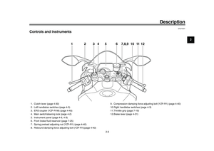 17
17 18
18 19
19 20
20 21
21 22
22 23
23 24
24 25
25 26
26 27
27 28
28 29
29 30
30 31
31 32
32 33
33 34
34 35
35 36
36 37
37 38
38 39
39 40
40 41
41 42
42 43
43 44
44 45
45 46
46 47
47 48
48 49
49 50
50 51
51 52
52 53
53 54
54 55
55 56
56 57
57 58
58 59
59 60
60 61
61 62
62 63
63 64
64 65
65 66
66 67
67 68
68 69
69 70
70 71
71 72
72 73
73 74
74 75
75 76
76 77
77 78
78 79
79 80
80 81
81 82
82 83
83 84
84 85
85 86
86 87
87 88
88 89
89 90
90 91
91 92
92 93
93 94
94 95
95 96
96 97
97 98
98 99
99 100
100 101
101 102
102 103
103 104
104 105
105 106
106 107
107 108
108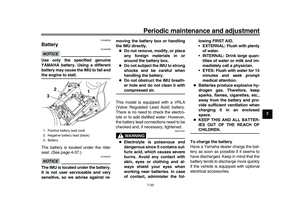 109
109 110
110 111
111 112
112 113
113 114
114 115
115 116
116 117
117 118
118 119
119 120
120 121
121 122
122 123
123 124
124 125
125 126
126 127
127 128
128 129
129