Page 49 of 114

Instrument and control functions
3-34
1
234
5
6
7
8
9
10
11
12
The spring preload setting is deter-
mined by measuring distance A, shown
in the illustration. The shorter distance
A is, the higher the spring preload; the
longer distance A is, the lower the
spring preload.
Rebound damping force
The rebound damping force is adjusted
on the right front fork leg only.
To increase the rebound damping force
and thereby harden the rebound damp-
ing, turn the adjusting screw in direction
(a). To decrease the rebound damping
force and thereby soften the rebound
damping, turn the adjusting screw in di-
rection (b).
TIP
Although the total number of clicks
of a damping force adjusting
mechanism may not exactly match
the above specifications due to
small differences in production, the
actual number of clicks always
represents the entire adjusting
range. To obtain a precise adjust-
ment, check the number of clicks
of each damping force adjusting
mechanism and to modify the
specifications as necessary.
When turning a damping force ad-
juster in direction (a), the 0 click
position and the 1 click positionmay be the same.
1. Spring preload adjusting bolt
1. Distance A
1
1
(a)
(b)
(a)
(b)
1
Spring preload setting:
Minimum (soft):Distance A = 19.0 mm (0.75 in)
Standard:
Distance A = 16.0 mm (0.63 in)
Maximum (hard): Distance A = 4.0 mm (0.16 in)1. Rebound damping force adjusting screw
1
(a)
(b)
Rebound damping setting:
Minimum (soft):12 click(s) in direction (b)*
Standard:
7 click(s) in direction (b)*
Maximum (hard): 1 click(s) in direction (b)*
* With the adjusting screw fully turned in direction (a)
2PP-9-E3.book 34 ページ 2016年9月13日 火曜日 午前9時7分
Page 50 of 114

Instrument and control functions
3-35
1
23
4
5
6
7
8
9
10
11
12
EAU57940
Adjusting th e shock absorber
assemblyThis shock absorber assembly is
equipped with a spring preload adjust-
ing ring and a rebound damping force
adjusting screw.NOTICE
ECA10102
To avoid damaging the mechanism,
do not attempt to turn beyond themaximum or minimum settings.
Spring preload
To increase the spring preload and
thereby harden the suspension, turn
the adjusting ring in direction (a). To de-
crease the spring preload and thereby
soften the suspension, turn the adjust-
ing ring in direction (b).
Align the appropriate notch in the
adjusting ring with the position in-
dicator on the shock absorber.
Use the special wrench and the
extension bar included in the own-
er’s tool kit to make the adjust-
ment. Rebound damping force
To increase the rebound damping force
and thereby harden the rebound damp-
ing, turn the adjusting screw in direction
(a). To decrease the rebound damping
force and thereby soften the rebound
damping, turn the adjusting screw in di-
rection (b).
1. Spring preload adjusting ring
2. Special wrench
3. Extension bar
4. Position indicatorSpring preload setting:
Minimum (soft):1
Standard:
4
Maximum (hard): 7
7654321
1(b) (a)
4
2
3
1. Rebound damping force adjusting screwRebound damping setting:
Minimum (soft):
3 turn(s) in direction (b)*
Standard: 1 1/2 turn(s) in direction (b)*
Maximum (hard): Adjusting screw fully turned in di-
rection (a)
* With the adjusting screw fully turned in direction (a)
1 (a)(b)
2PP-9-E3.book 35 ページ 2016年9月13日 火曜日 午前9時7分
Page 51 of 114

Instrument and control functions
3-36
1
234
5
6
7
8
9
10
11
12
TIPTo obtain a precise adjustment, it is ad-
visable to check the actual total number
of turns of the damping force adjusting
mechanism. This adjustment range
may not exactly match the specifica-
tions listed due to small differences inproduction.
WARNING
EWA10222
This shock absorber assembly con-
tains highly pressurized nitrogen
gas. Read and understand the fol-
lowing information before handling
the shock absorber assembly.
Do not tamper with or attempt to
open the cylinder assembly.
Do not subject the shock ab-
sorber assembly to an open
flame or other high heat source.
This may cause the unit to ex-
plode due to excessive gas
pressure.
Do not deform or damage the
cylinder in any way. Cylinder
damage will result in poor
damping performance.
Do not dispose of a damaged or worn-out shock absorber as-
sembly yourself. Take the shock
absorber assembly to a Yamaha
dealer for any service.
EAU63080
Luggage strap holdersThere are ten luggage strap holders,
eight below the passenger seat and
one on each passenger footrest.1. Luggage strap holder
1
1
1
2PP-9-E3.book 36 ページ 2016年9月13日 火曜日 午前9時7分
Page 52 of 114

Instrument and control functions
3-37
1
23
4
5
6
7
8
9
10
11
12
EAU15306
SidestandThe sidestand is located on the left side
of the frame. Raise the sidestand or
lower it with your foot while holding the
vehicle upright.TIPThe built-in sidestand switch is part of
the ignition circuit cut-off system, which
cuts the ignition in certain situations.
(See the following section for an expla-
nation of the ignition circuit cut-off sys-tem.)
WARNING
EWA10242
The vehicle must not be ridden with
the sidestand down, or if the sides-
tand cannot be properly moved up
(or does not stay up), otherwise the
sidestand could contact the ground
and distract the operator, resulting
in a possible loss of control.
Yamaha’s ignition circuit cut-off
system has been designed to assist
the operator in fulfilling the respon-
sibility of raising the sidestand be-
fore starting off. Therefore, check
this system regularly and have a Yamaha dealer repair it if it does not
function properly.
EAU54491
Ignition circuit
cut-off systemThe ignition circuit cut-off system (com-
prising the sidestand switch, clutch
switch and neutral switch) has the fol-
lowing functions.
It prevents starting when the trans-
mission is in gear and the sides-
tand is up, but the clutch lever is
not pulled.
It prevents starting when the trans-
mission is in gear and the clutch le-
ver is pulled, but the sidestand is
still down.
It cuts the running engine when the
transmission is in gear and the sid-
estand is moved down.
Periodically check the operation of the
ignition circuit cut-off system according
to the following procedure.
2PP-9-E3.book 37 ページ 2016年9月13日 火曜日 午前9時7分
Page 53 of 114

Instrument and control functions
3-38
1
234
5
6
7
8
9
10
11
12
With the engine turned off:
1. Move the sidestand down.
2. Make sure that the start/engine stop switch is set to “ ”.
3. Turn the key on.
4. Shift the transmission into the neutral position.
5. Push the “ ” side of the start/engine stop switch.
Does the engine start?
With the engine still running:
6. Move the sidestand up.
7. Keep the clutch lever pulled.
8. Shift the transmission into gear.
9. Move the sidestand down.
Does the engine stall?
After the engine has stalled:
10. Move the sidestand up.
11. Keep the clutch lever pulled.
12. Push the “ ” side of the start/engine stop switch.
Does the engine start?
The system is OK. The motorcycle can be ridden.
YES NO YES NO YES NO
The neutral switch may not be working correctly.
The motorcycle should not be ridden until
checked by a Yamaha dealer.
The clutch switch may not be working correctly.
The motorcycle should not be ridden until
checked by a Yamaha dealer.The sidestand switch may not be working correctly.
The motorcycle should not be ridden until
checked by a Yamaha dealer. The vehicle must be placed on the center-
stand during this inspection.If a malfunction is noted, have a Yamaha
dealer check the system before riding.
WARNING
2PP-9-E3.book 38 ページ 2016年9月13日 火曜日 午前9時7分
Page 54 of 114

Instrument and control functions
3-39
1
23
4
5
6
7
8
9
10
11
12
EAU49453
Auxiliary DC jack
WARNING
EWA14361
To prevent electrical shock or
short-circuiting, make sure that the
cap is installed when the auxiliaryDC jack is not being used.NOTICE
ECA15432
The accessory connected to the
auxiliary DC jack should not be used
with the engine turned off, and the
load must never exceed 24 W (2A),
otherwise the fuse may blow or thebattery may discharge.
This vehicle is equipped with an auxilia-
ry DC jack.
A 12-V accessory connected to the
auxiliary DC jack can be used when the
key is in the “ON” position and should
only be used when the engine is run-
ning.
To use the auxiliary DC jack 1. Turn the key to “OFF”.
2. Remove the auxiliary DC jack cap. 3. Turn the accessory off.
4. Insert the accessory plug into the
auxiliary DC jack.
5. Turn the key to “ON”, and then start the engine. (See page 5-1.)
6. Turn the accessory on.
EAU70641
Auxiliary DC connectorThis vehicle is equipped with an auxilia-
ry DC connector. Consult your Yamaha
dealer before installing any accesso-
ries.
1. Auxiliary DC jack cap
1. Auxiliary DC jack
11
2PP-9-E3.book 39 ページ 2016年9月13日 火曜日 午前9時7分
Page 55 of 114

4-1
1
2
345
6
7
8
9
10
11
12
For your safety – pre-operation checks
EAU15599
Inspect your vehicle each time you use it to make sure the vehicle is in safe operating condition. Always follow the inspection
and maintenance procedures and schedules described in the Owner’s Manual.
WARNING
EWA11152
Failure to inspect or maintain the vehicle properly increases the possibility of an accident or equipment damage.
Do not operate the vehicle if you find any problem. If a problem cannot be corrected by the procedures provided inthis manual, have the vehicle inspected by a Yamaha dealer.
Before using this vehicle, check the following points:
ITEM CHECKS PAGE
Fuel Check fuel level in fuel tank.
Refuel if necessary.
Check fuel line for leakage.
Check fuel tank breather hose and overflow hose for obstructions, cracks or
damage, and check hose connections. 3-25, 3-27
Engine oil Check oil level in engine.
If necessary, add recommended oil to specified level.
Check vehicle for oil leakage. 6-11
Coolant Check coolant level in reservoir.
If necessary, add recommended coolant to specified level.
Check cooling system for leakage. 6-14
Front brake Check operation.
If soft or spongy, have Yamaha dealer bleed hydraulic system.
Check brake pads for wear.
Replace if necessary.
Check fluid level in reservoir.
If necessary, add specified brake fluid to specified level.
Check hydraulic system for leakage. 6-22, 6-23
2PP-9-E3.book 1 ページ 2016年9月13日 火曜日 午前9時7分
Page 56 of 114

For your safety – pre-operation checks
4-2
1
2
34
5
6
7
8
9
10
11
12
Rear brake Check operation.
If soft or spongy, have Yamaha dealer bleed hydraulic system.
Check brake pads for wear.
Replace if necessary.
Check fluid level in reservoir.
If necessary, add specified brake fluid to specified level.
Check hydraulic system for leakage. 6-22, 6-23
Clutch Check operation.
Lubricate cable if necessary.
Check lever free play.
Adjust if necessary. 6-21
Throttle grip Make sure that operation is smooth.
Check throttle grip free play.
If necessary, have Yamaha dealer adjust throttle grip free play and lubricate cable
and grip housing. 6-17, 6-27
Control cables Make sure that operation is smooth.
Lubricate if necessary. 6-27
Drive chain Check chain slack.
Adjust if necessary.
Check chain condition.
Lubricate if necessary. 6-25, 6-26
Wheels and tires Check for damage.
Check tire condition and tread depth.
Check air pressure.
Correct if necessary. 6-18, 6-20
Brake and shift pedals Make sure that operation is smooth.
Lubricate pedal pivoting points if necessary. 6-28
Brake and clutch levers Make sure that operation is smooth.
Lubricate lever pivoting points if necessary. 6-28
Centerstand, sidestand Make sure that operation is smooth.
Lubricate pivots if necessary. 6-29
Chassis fasteners Make sure that all nuts, bolts
and screws are properly tightened.
Tighten if necessary. —
ITEM CHECKS PAGE
2PP-9-E3.book 2 ページ 2016年9月13日 火曜日 午前9時7分
 1
1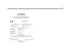 2
2 3
3 4
4 5
5 6
6 7
7 8
8 9
9 10
10 11
11 12
12 13
13 14
14 15
15 16
16 17
17 18
18 19
19 20
20 21
21 22
22 23
23 24
24 25
25 26
26 27
27 28
28 29
29 30
30 31
31 32
32 33
33 34
34 35
35 36
36 37
37 38
38 39
39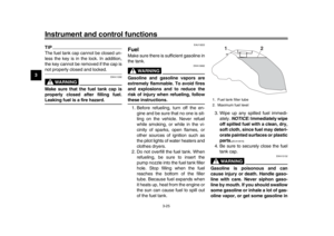 40
40 41
41 42
42 43
43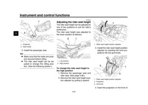 44
44 45
45 46
46 47
47 48
48 49
49 50
50 51
51 52
52 53
53 54
54 55
55 56
56 57
57 58
58 59
59 60
60 61
61 62
62 63
63 64
64 65
65 66
66 67
67 68
68 69
69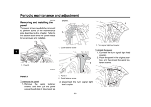 70
70 71
71 72
72 73
73 74
74 75
75 76
76 77
77 78
78 79
79 80
80 81
81 82
82 83
83 84
84 85
85 86
86 87
87 88
88 89
89 90
90 91
91 92
92 93
93 94
94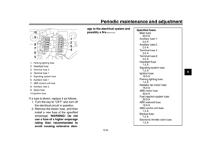 95
95 96
96 97
97 98
98 99
99 100
100 101
101 102
102 103
103 104
104 105
105 106
106 107
107 108
108 109
109 110
110 111
111 112
112 113
113