Page 516 of 584

||
MAINTENANCE AND SERVICING
514
H8 AGM battery with strap
•When replacing the start battery anAbsorbed Glass Mat (AGM) must be used.
•When replacing the start battery, a new bat-tery with the same specifications and dimen-sions must be used. The battery should onlybe replaced by a trained and qualified Volvoservice technician.
Related information
•Jump starting (p. 395)
•Battery symbols (p. 516)
Support battery
Vehicles equipped with Start/Stop are equippedwith two 12-volt batteries.
In addition to a heavy-duty start battery, modelswith Start/Stop also have a support battery thatprovides extra current during the Start/Stopfunction's start sequence.
The following table shows the specifications forthe support battery:
Current (V)12
Cold start capacity (ColdCranking Amperes -CCA) (A)170
Dimensions, L×W×H in.(mm)5.9×3.5×5.1(150×90×130)
Capacity (Ah)10
•When replacing the start battery or supportbattery in a vehicle with Start/Stop, anAbsorbed Glass Mat (AGM) must be used.
•The greater the current consumption in thevehicle, the more the generator has to oper-ate and the battery is charged. This increasesfuel consumption.
•When the start battery's charge is below theminimum permitted level, the Start/Stopfunction will be disabled.
When the Start/Stop function is temporarily disa-bled due to high current consumption:
•The engine will auto-start, even if the brakepedal is depressed.
The support battery does not normally requiredmore service than the start battery. If questionsarise, consult a Volvo retailer or trained and quali-fied Volvo service technician.
CAUTION
When connecting an external start battery ora battery charger, the Start/Stop function maybe temporarily disabled if the negative termi-nal on the vehicle's start battery is used toconnect an external start battery or a batterycharger. Only the negative connection pointin the engine compartment may be used as aground point.
Page 517 of 584
MAINTENANCE AND SERVICING
515
NOTE
If the start battery is completely dischargedand the vehicle has no normal electrical func-tions, and the engine is then started using anauxiliary battery or battery charger, theStart/Stop function will be activated. Theengine can then be auto-stopped but may notauto-start again due to an insufficient chargelevel in the start battery.
To help ensure auto-start, the start batteryshould be charged first. At a temperature ofapprox. 60 °F (15 °C), the battery should becharged for at least 1 hour, preferably usingan external battery charger. At lower tempera-tures, the battery should be charged for3–4 hours.
If a charger is not available, it is advisable todisable the Start/Stop function until the bat-tery is sufficiently recharged.
Related information
•Start battery (p. 512)
Hybrid battery
The vehicle's electric motor is powered by arechargeable, maintenance-free, lithium-ionhybrid battery.
The vehicle cannot be started if the hybridbattery is completely discharged.
WARNING
The vehicle's hybrid battery may only be serv-iced or replaced by a trained and qualifiedVolvo service technician.
Battery coolant
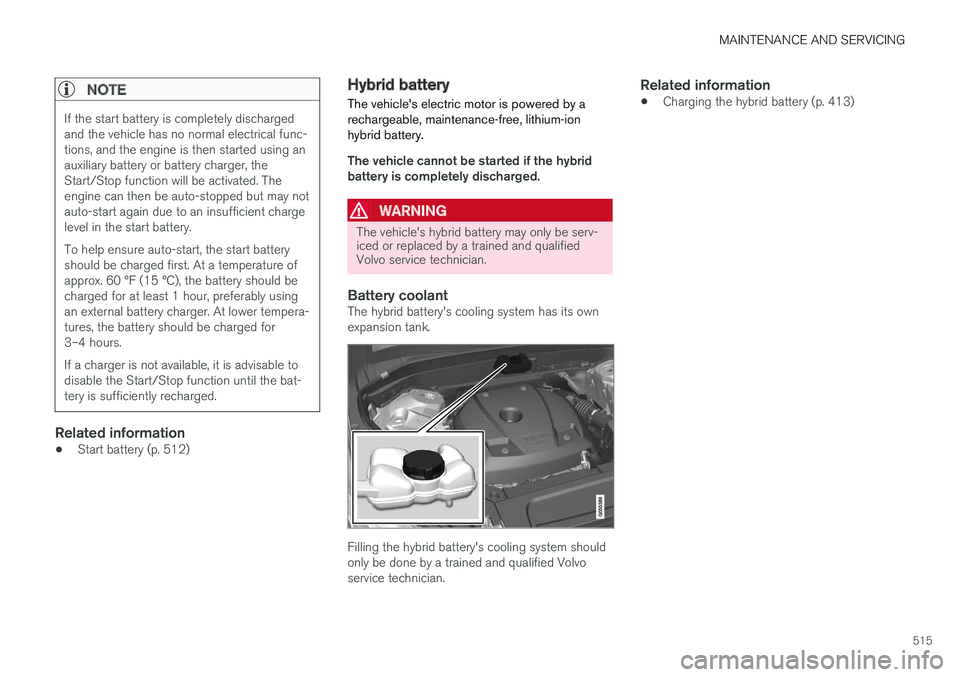
The hybrid battery's cooling system has its ownexpansion tank.
Filling the hybrid battery's cooling system shouldonly be done by a trained and qualified Volvoservice technician.
Related information
•Charging the hybrid battery (p. 413)
Page 518 of 584

MAINTENANCE AND SERVICING
516
Battery symbols
There are information and warning symbols onthe battery.
Wear protective goggles.
See the owner's manual foradditional information.
Keep batteries away fromchildren.
Batteries contain corrosiveacid.
Avoid smoking, openflames, and/or sparks.
Risk of explosion
Recycle properly
NOTE
A used battery should be disposed of in anenvironmentally responsible manner. Consultyour Volvo retailer or take the battery to arecycling station.
Related information
•Start battery (p. 512)
Fuses
The fuses help protect the vehicle's electricalcomponents from overloading or short circuits.
WARNING
Never use metal objects or fuses with higheramperage than those stated on the lists offuses. Doing so could seriously damage oroverload the vehicle's electrical system.
Orange wires may only be handled by trainedand authorized Volvo service technicians orlicensed electricians.
A number of component in the vehicle usedhigh voltage electrical current and can be verydangerous to touch.
Do not touch any components that are notclearly described in this owner's information.
If an electrical component fails to function, thismay be due to a blown fuse. If the same fuseblows repeatedly, this indicates a problem withthe component, which should be inspected by atrained and qualified Volvo service technician.
Page 519 of 584

MAINTENANCE AND SERVICING
517
Location of the fuseboxes
Engine compartment
Under the glove compartment
Cargo compartment
Related information
•Replacing fuses (p. 517)
•Fuses in the cargo compartment (p. 527)
•Fuses in the engine compartment (p. 518)
•Fuses in the passenger compartment(p. 523)
Replacing fuses
The fuses help protect the vehicle's electricalcomponents from overloading or short circuits.
Fuse replacement
1. See the list of fuse boxes for their locations.
2. Pull the fuse straight out and examine it fromthe side to see if the curved metal wire in thefuse is intact.
3. If the wire is broken, insert a new fuse of thesame color and amperage (written on thefuse).
WARNING
Never use metal objects or fuses with higheramperage than those stated on the followingpages. Doing so could seriously damage oroverload the vehicle's electrical system.
Related information
•Fuses (p. 516)
•Fuses in the cargo compartment (p. 527)
•Fuses in the engine compartment (p. 518)
•Fuses in the passenger compartment(p. 523)
Page 520 of 584
MAINTENANCE AND SERVICING
518
Fuses in the engine compartment
The fuses in the engine compartment help pro-tect electrical components such as engine andbrake functions.
Page 521 of 584
MAINTENANCE AND SERVICING
}}
519
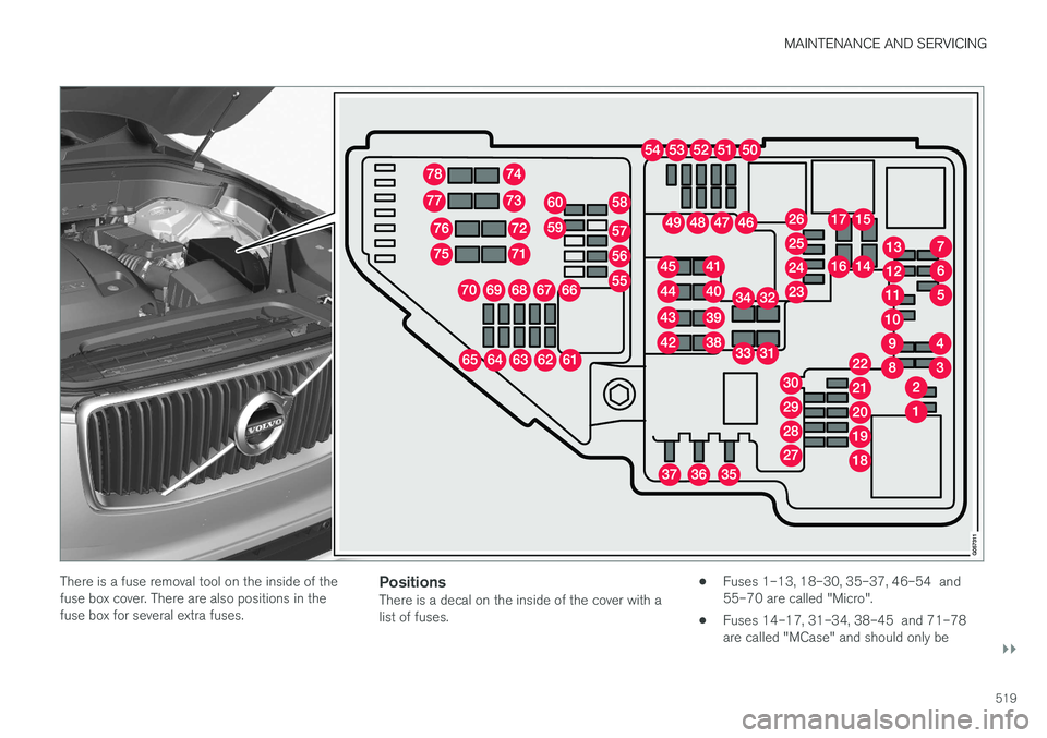
There is a fuse removal tool on the inside of thefuse box cover. There are also positions in thefuse box for several extra fuses.
Positions
There is a decal on the inside of the cover with alist of fuses.
•Fuses 1–13, 18–30, 35–37, 46–54 and55–70 are called "Micro".
•Fuses 14–17, 31–34, 38–45 and 71–78are called "MCase" and should only be
Page 522 of 584
![VOLVO XC90 TWIN ENGINE HYBRID 2017 Owners Manual ||
MAINTENANCE AND SERVICING
* Option/accessory, for more information, see Introduction.520
replaced by a trained and qualified Volvoservice technician.
Function[A]
Converter for controlling feed toth](/manual-img/45/59300/w960_59300-521.png "VOLVO XC90 TWIN ENGINE HYBRID 2017 Owners Manual ||
MAINTENANCE AND SERVICING
* Option/accessory, for more information, see Introduction.520
replaced by a trained and qualified Volvoservice technician.
Function[A]
Converter for controlling feed toth")
||
MAINTENANCE AND SERVICING
* Option/accessory, for more information, see Introduction.520
replaced by a trained and qualified Volvoservice technician.
Function[A]
Converter for controlling feed tothe rear axle electric motor5
––
––
Control module for actuator forengaging/changing gears5
High Voltage Coolant Heatercontrol module5
Control module for: A/C, chargemodule, heat exchanger cut-offvalve, cut-off valve for coolantthrough the climate system
5
Hybrid battery control module;high-voltage converter for com-bined high-voltage generator/starter motor with 500 V–12 Vvoltage converter
5
––
Converter for controlling feed tothe rear axle electric motor10
Function[A]
Hybrid battery control modulefor high-voltage converter forcombined high-voltage genera-tor/starter motor with 500 V–12V voltage converter
10
Charging module5
Cut-off valve for hybrid batterycoolant; coolant pump 1 forhybrid battery
10
Coolant pump for electric drivesystem10
Hybrid component cooling fan25
––
––
––
––
––
––
––
––
Function[A]
Front USB socket*5
12-volt socket in the front tun-nel console15
12-volt socket on the rear side
of the tunnel consoleA
12-volt socket in the tunnel con-
sole between the rear seats B
15
12-volt socket in the cargo com-partment
USB sockets for iPad holdersB
15
––
––
––
––
Heated windshield* driver sideShunt
Heated windshield* driver side40
Headlight washers*25
Windshield washer25
––
Page 523 of 584
![VOLVO XC90 TWIN ENGINE HYBRID 2017 Owners Manual MAINTENANCE AND SERVICING
}}
* Option/accessory, for more information, see Introduction.521
Function[A]
Horn20
Alarm siren*5
Brake system control module(valves, parking brake)40
Windshield wipers30
Ta](/manual-img/45/59300/w960_59300-522.png "VOLVO XC90 TWIN ENGINE HYBRID 2017 Owners Manual MAINTENANCE AND SERVICING
}}
* Option/accessory, for more information, see Introduction.521
Function[A]
Horn20
Alarm siren*5
Brake system control module(valves, parking brake)40
Windshield wipers30
Ta")
MAINTENANCE AND SERVICING
}}
* Option/accessory, for more information, see Introduction.521
Function[A]
Horn20
Alarm siren*5
Brake system control module(valves, parking brake)40
Windshield wipers30
Tailgate window washer25
Heated windshield*, passengerside40
––
Brake system control module(ABS pump)40
––
Heated windshield*, passengersideShunt
Feed when ignition is switchedon to: engine control module,transmission components, elec-trical power steering, centralelectrical module
5
Exterior vehicle sound (certainmarkets)5
Passenger side headlight7,5
Function[A]
––
––
––
Air bags; Occupant Weight Sen-sor (OWS)5
Driver side headlight7.5
Accelerator pedal sensor5
Transmission control module;Gear selector control module15
Engine control module5
––
––
––
––
Engine control module; Actuator;Turbo-charger valve20
Solenoids; Valves; Engine cool-ing system thermostat10
Vacuum regulators; Valve7.5
Function[A]
Spoiler shutter control module;Radiator shutter control module;Fuel leakage detection
5
––
Heated oxygen sensors (frontand rear)15
Oil pump solenoid; A/C mag-netic coupling; heated oxygensensor (center)
15
––
Engine control module20
Ignition coils; Spark plugs15
––
––
Transmission oil pump controlmodule30
Vacuum pump control module40
Transmission actuator25
––