Page 108 of 640

1083-1. Key information
NOTICE
■To prevent key damage
● Do not drop the keys, subject them to strong shocks or bend them.
● Do not expose the keys to high temperatures for long periods of time.
● Do not get the keys wet or wash them in an ultrasonic washer, etc.
● Do not attach metallic or magnetic materials to the keys or place the keys
close to such materials.
● Do not disassemble the keys.
● Do not attach a sticker or anything else to the surface of the electronic key.
● Do not place the keys near objects that produce magnetic fields, such as
TVs, audio systems and induction cooker s, or medical electrical equip-
ment, such as low-frequency therapy equipment.
■ Carrying the electronic key on your person (type D)
Carry the electronic key 10 cm (3.9 in.) or more away from electric appli-
ances that are turned on. Radio waves emitted from electric appliances
within 10 cm (3.9 in.) of the electronic key may interfere with the key, caus-
ing the key to not function properly.
■ In case of a smart entry & start system malfunction or other key-related
problems (type D)
Take your vehicle with all the electronic keys provided with your vehicle to
your Toyota dealer.
■ When an electronic key is lost (type D)
If the electronic key remains lost, the risk of vehicle theft increases signifi-
cantly. Visit your Toyota dealer immediately with all remaining electronic
keys that was provided with your vehicle.
Page 114 of 640

1143-2. Opening, closing and locking the doors
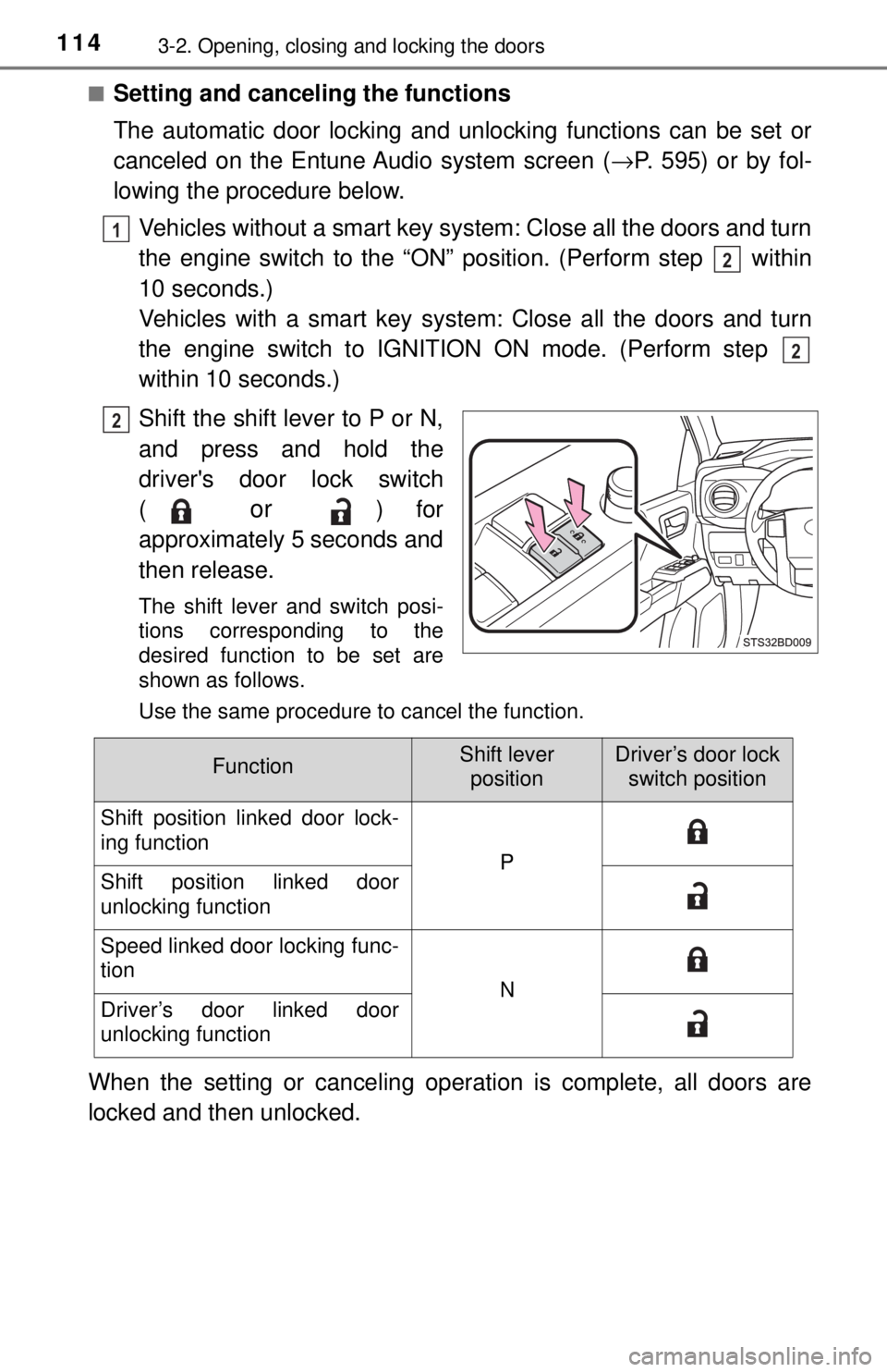
■Setting and canceling the functions
The automatic door locking and unlocking functions can be set or
canceled on the Entune Audio system screen (→P. 595) or by fol-
lowing the procedure below.
Vehicles without a smart key system: Close all the doors and turn
the engine switch to the “ON” position. (Perform step within
10 seconds.)
Vehicles with a smart key syst em: Close all the doors and turn
the engine switch to IGNITION ON mode. (Perform step
within 10 seconds.)
Shift the shift lever to P or N,
and press and hold the
driver's door lock switch
(
or ) for
approximately 5 seconds and
then release.
The shift lever and switch posi-
tions corresponding to the
desired function to be set are
shown as follows.
Use the same procedure to cancel the function.
When the setting or canceling operation is complete, all doors are
locked and then unlocked.
1
2
2
2
FunctionShift lever positionDriver’s door lock switch position
Shift position linked door lock-
ing function
PShift position linked door
unlocking function
Speed linked door locking func-
tion
NDriver’s door linked door
unlocking function
Page 124 of 640

1243-2. Opening, closing and locking the doors
■Conditions affecting operation
The smart key system uses weak radio waves. In the following situations, the
communication between the electronic key and the vehicle may be affected,
preventing the smart key system, wireless remote control and engine immobi-
lizer system from operating properly. (Ways of coping: →P. 557)
● When the electronic key battery is depleted
● Near a TV tower, electric power plant, gas station, radio station, large dis-
play, airport or other facility that generates strong radio waves or electrical
noise
● When carrying a portable radio, cellular phone, cordless phone or other
wireless communication device
● When the electronic key is in contact with, or is covered by the following
metallic objects
• Cards to which aluminum foil is attached
• Cigarette boxes that have aluminum foil inside
• Metallic wallets or bags
• Coins
• Hand warmers made of metal
• Media such as CDs and DVDs
● When multiple electronic keys are in the vicinity
● When other wireless keys (that emit radio waves) are being used nearby
● When carrying the electronic key together with the following devices that
emit radio waves
• Another vehicle’s electronic key or a wireless key that emits radio waves
• Personal computers or personal digital assistants (PDAs)
• Digital audio players
• Portable game systems
● If window tint with a metallic content or metallic objects are attached to the
back window
● When the electronic key is placed near a battery charger or electronic
devices
Page 189 of 640
1894-2. Driving procedures
4
Driving
Engine (ignition) switch (vehicles without a
smart key system)
Automatic transmission
Check that the parking brake is set.
Check that the shift lever is set in P.
Firmly depress the brake pedal.
Turn the engine switch to the “S TART” position to start the engine.
Manual transmission
Check that the parking brake is set.
Check that the shift lever is set in N.
Firmly depress the clutch pedal.
Turn the engine switch to the “START” position to start the engine.
“LOCK”
The steering wheel is locked and
the key can be removed. (Vehicles
with an automatic transmission:
The key can be removed only
when the shift lever is in P.)
“ACC”
Some electrical components such
as the audio system can be used.
“ON”
All electrical components can be used.
“START”
For starting the engine.
Starting the engine
Changing the engine switch positions
1
2
3
4
1
2
3
4
1
2
3
4
Page 193 of 640
1934-2. Driving procedures
4
Driving
Stop the vehicle.
Set the parking brake (→P. 205), and shift the shift lever to P.
Press the engine switch.
Release the brake pedal and check that the display on the instru-
ment cluster is off.
Modes can be changed by pressing the engine switch with brake
pedal released. (The mode changes ea ch time the switch is pressed.)
Off
*
The emergency flashers can be
used.
ACCESSORY mode
Some electrical components such
as the audio system can be used.
“ACCESSORY” will be displayed
on the multi-information display.
IGNITION ON mode
All electrical components can be
used.
“IGNITION ON” will be displayed
on the multi-information display.
*: If the shift lever is in a position other than P when turning off the
engine, the engine switch will be
turned to ACCESSORY mode, not
to off.
Stopping the engine
Changing engine switch modes
1
2
3
4
1
2
3
Page 227 of 640

2274-5. Using the driving support systems
4
Driving
●The shape of the obstacle may prevent the sensor from detecting it. Pay
particular attention to the following obstacles:
• Wires, fences, ropes, etc.
• Cotton, snow and other materials that absorb sound waves
• Sharply-angled objects
• Low obstacles
• Tall obstacles with upper sections projecting outwards in the direction of
your vehicle
● The following situations may occur during use.
• Depending on the shape of the obstacle and other factors, the detection
distance may shorten, or detection may be impossible.
• Obstacles may not be detected if they are too close to the sensor.
• There will be a short delay between obstacle detection and display. Even at slow speeds, there is a possibility that the obstacle will come within the
sensor’s detection areas before the display is shown and the warning
beep sounds.
• Thin posts or objects lower than the sensor may not be detected for colli- sion when approached, even if they have been detected once.
• It might be difficult to hear beeps due to the volume of audio system or air flow noise of air conditioning system.
■ If a message is displayed on the multi-information display
→P. 529
■ Customization
Settings (e.g. buzzer volume) can be changed.
(Customizable features →P. 595)
■ Certification (Canada only)
This ISM device complies with Canadian ICES-001.
Page 229 of 640

2294-5. Using the driving support systems
4
Driving
Rear view monitor system
Vehicles with Entune Audio Plus or Entune Premium Audio
(Audio system types: →P. 284)
Refer to the “NAVIGATION AND MULTIMEDIA SYSTEM
OWNER’S MANUAL”.
Vehicles with Entune Au dio (Audio system types: →P. 284)
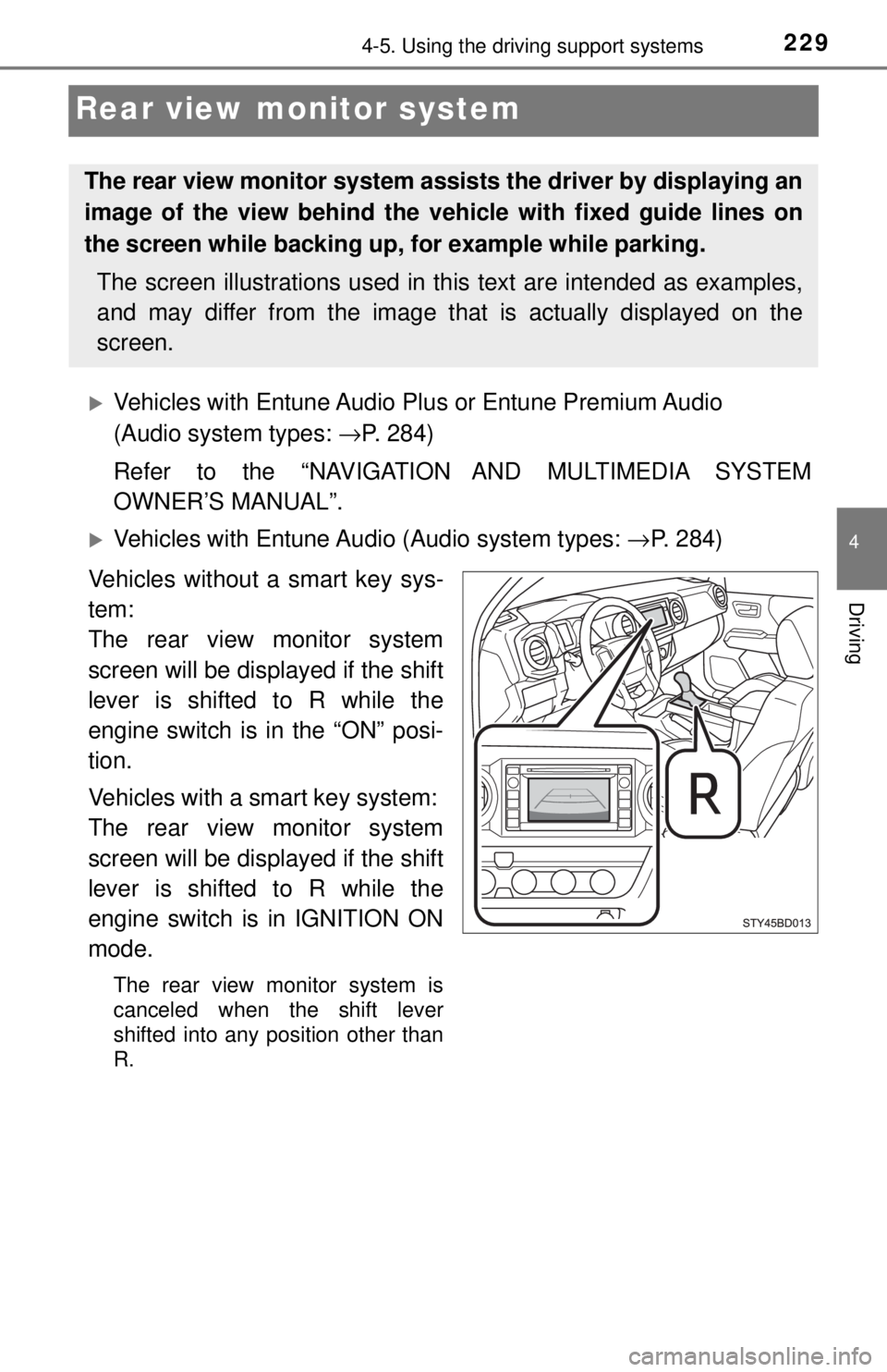
Vehicles without a smart key sys-
tem:
The rear view monitor system
screen will be displayed if the shift
lever is shifted to R while the
engine switch is in the “ON” posi-
tion.
Vehicles with a smart key system:
The rear view monitor system
screen will be displayed if the shift
lever is shifted to R while the
engine switch is in IGNITION ON
mode.
The rear view monitor system is
canceled when the shift lever
shifted into any position other than
R.
The rear view monitor system assists the driver by displaying an
image of the view behind the veh icle with fixed guide lines on
the screen while backing up, for example while parking.
The screen illustrations used in this text are intended as examples,
and may differ from the image that is actually displayed on the
screen.
Page 240 of 640

2404-5. Using the driving support systems
Rear Cross Traffic Alert buzzer (R ear Cross Traffic Alert function
only)
When a vehicle approaching from the right or left rear of the vehicle is
detected, a buzzer sounds from behind the left-hand rear pillar.
■ The outside rear view mi rror indicators visibility
When under strong sunlight, the outside rear view mirror indicator may be dif-
ficult to see.
■ Rear Cross Traffic Alert buzzer hearing
Rear Cross Traffic Alert function may be difficult to hear over noises such as
high audio volume.
■ When there is a malfunction in the Blind Spot Monitor system
If a system malfunction is detected due to any of the following reasons,\
warn-
ing light will be turned on (vehicles without a multi-information display) or
messages will be displayed (vehicles with a multi-information display):
( →P. 517, 530)
● There is a malfunction with the sensors
● The sensors have become dirty
● The outside temperature is extremely high or low
● The sensor voltage has become abnormal
■ Certification for the B lind Spot Monitor system
For vehicles sold in the U.S.A.
FCC ID: OAYSRR2A
This device complies with part 15 of the FCC Rules. Operation is subject to
the following two conditions:
(1) This device may not cause harmful interference, and
(2) this device must accept any interference received, including interference
that may cause undesired operation.
FCC Warning
Changes or modifications not expressly approved by the party responsible for
compliance could void the user’s authority to operate the equipment.
For vehicles sold in Canada
Applicable law: Canada 310
This device complies with Industry Canada licence-exempt RSS standard(s).
Operation is subject to the following two conditions: (1) this device may not
cause interference, and (2) this device must accept any interference, includ-
ing interference that may cause undesired operation of the device.
Frequency bands: 24.05 – 24.25 GHz
Output power: less than 20 milliwatts
3