2017 TOYOTA MIRAI ESP
[x] Cancel search: ESPPage 45 of 464

451-1. For safe use
1
For safety and security
MIRAI_OM_USA_OM62023U■
SRS airbag deployment conditions (S RS side and curtain shield airbags)
● The SRS side and curtain shield airbags will deploy in the event of an
impact that exceeds the set threshold level (the level of force corresponding
to the impact force produced by an approximately 3300 lb. [1500 kg] vehi\
cle
colliding with the vehicle cabin from a direction perpendicular to the vehicle
orientation at an approximate speed of 12 - 18 mph [20 - 30 km/h]).
● The SRS curtain shield airbags will deploy in the event of vehicle rollover.
● The SRS side and curtain shield airbags may also deploy in the event of a
severe frontal collision.
■ Conditions under which the SRS airbags may deploy (inflate), other than
a collision
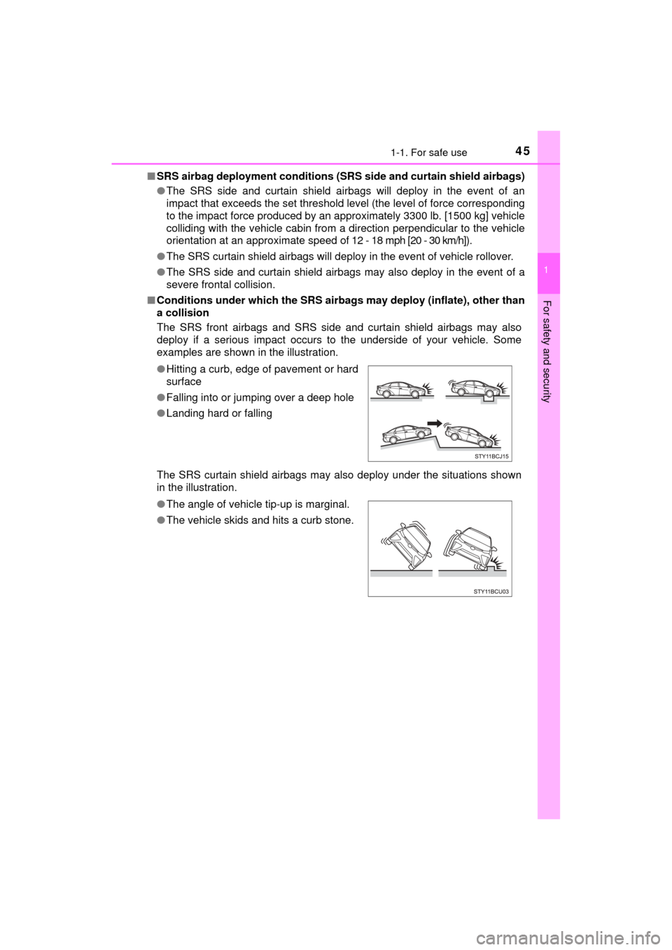
The SRS front airbags and SRS side and curtain shield airbags may also
deploy if a serious impact occurs to the underside of your vehicle. Some
examples are shown in the illustration.
The SRS curtain shield airbags may also deploy under the situations shown
in the illustration. ●Hitting a curb, edge of pavement or hard
surface
● Falling into or jumping over a deep hole
● Landing hard or falling
● The angle of vehicle tip-up is marginal.
● The vehicle skids and hits a curb stone.
Page 73 of 464

731-2. Theft deterrent system
1
For safety and security
MIRAI_OM_USA_OM62023U
■System maintenance
The vehicle has a maintenance-free type immobilizer system.
■ Conditions that may cause the system to malfunction
●If the grip portion of the key is in contact with a metallic object
● If the key is in close proximity to or touching a key registered to the security
system (key with a built-in transponder chip) of another vehicle
■ Certification for the immobilizer system
FCC ID: NI4TMIMB-3
This device complies with part 15 of the FCC Rules. Operation is subject to
the following two conditions: (1) This device may not cause harmful interfer-
ence, and (2) this device must accept any interference received, including
interference that may cause undesired operation.
Changes or modifications not expressly approved by the party responsible for
compliance could void the user’s authority to operate the equipment.
WARNING
■ Certifications for the immobilizer system
Changes or modifications not expressly approved by the party responsible
for compliance could void the user’s authority to operate the equipment.
NOTICE
■To ensure the system operates correctly
Do not modify or remove the system. If modified or removed, the proper
operation of the system cannot be guaranteed.
Page 88 of 464

882. Fuel cell vehicle
MIRAI_OM_USA_OM62023U■
Power output restriction
When the power output is restricted, the vehicle may fail to accelerate or even
decelerate, even though the accelerator pedal is depressed. If a safe driving
speed cannot be maintained, stop the vehicle in a safe place away from the
traffic. This may be caused by the following conditions:
●The coolant temperature may be too high. This can be caused by driving
conditions such as repeated sudden acceleration and deceleration, continu-
ous driving on an incline, continuous driving at high altitudes with a high
load, etc. In such situations, the power output restriction indicator (amber) is
displayed on the main display, “High FC Temperature Reduced Power” is
displayed on the multi-information display, and the power output is
restricted. Once the coolant returns to normal temperature, the power out-
put will return to normal. ( →P. 377)
● The remaining fuel may be low. After the low fuel warning indicator comes
on, the output power will be gradually restricted in order to extend the possi-
ble driving distance. Once getting to this point, the remaining driving dis-
tance possible is short. Immediately refill the vehicle with hydrogen.
● On cold days, the low fuel warning indicator comes on faster than usual and
the output power is restricted.
■ Vehicle proximity notification system
In the following cases, the vehicle proximity notification system may be diffi-
cult to hear for people around.
●In very noisy areas
● In wind or rain
Also, because the vehicle proximity notification system is located in the front
of the vehicle, it may be more difficult to hear from the rear of the vehicle
compared to the front.
■ Electromagnetic waves (EMF)
●High-voltage parts and cables in fuel cell vehicles have an electromagne\
tic
shielding configuration, and therefore emit approximately the same amount
of electromagnetic waves as conventional gasoline-powered vehicles or
home electronic appliances.
● Your vehicle may cause sound interference in some third party-produced
radio parts.
■ Traction battery
The traction battery has a limited service life. The lifespan of the traction bat-
tery can change according to driving style and driving conditions.
Page 125 of 464

1254-2. Opening, closing and locking the doors
4
Operation of each component
MIRAI_OM_USA_OM62023U■
Conditions affecting the operation of the smart key system or wireless
remote control
→P. 134
■ Customization
Settings (e.g. unlocking function using a key) can be changed.
(Customizable features: →P. 435)
WARNING
■To prevent an accident
Observe the following precautions while driving the vehicle.
Failure to do so may result in a door opening and an occupant falling out,
resulting in death or serious injury.
● Ensure that all doors are properly closed and locked.
● Do not pull the inside handle of the doors while driving.
Be especially careful for the front doors, as the doors may be opened
even if the inside lock buttons are in locked position.
● Set the rear door child-protector locks when children are seated in the rear
seats.
■ When opening or closing a door
Check the surroundings of the vehicle such as whether the vehicle is on an
incline, whether there is enough space for a door to open and whether a
strong wind is blowing.
When opening or closing the door, hold the door handle tightly to prepare
for any unpredictable movement.
■ When using the wireless remote control and operating the power win-
dows
Operate the power window after checking to make sure that there is no pos-
sibility of any passenger having any of their body parts caught in the win-
dow. Also, do not allow children to operate the wireless remote control. It is
possible for children and other passengers to get caught in the power win-
dow.
Page 132 of 464

1324-2. Opening, closing and locking the doors
MIRAI_OM_USA_OM62023U■
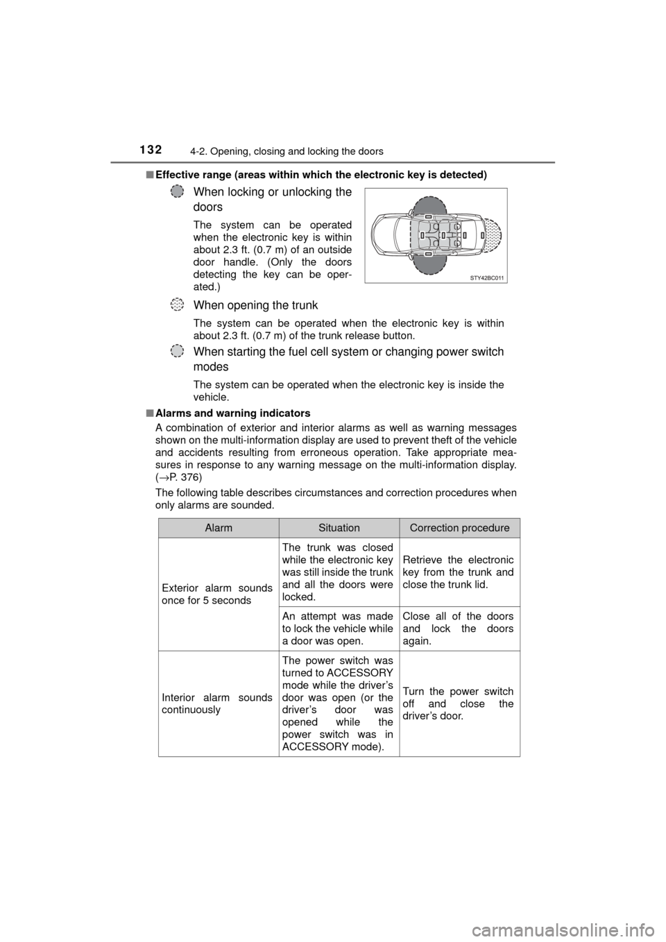
Effective range (areas within whic h the electronic key is detected)
■ Alarms and warning indicators
A combination of exterior and interior alarms as well as warning messages
shown on the multi-information display are used to prevent theft of the vehicle
and accidents resulting from erroneous operation. Take appropriate mea-
sures in response to any warning message on the multi-information display.
(→P. 376)
The following table describes circumstances and correction procedures when
only alarms are sounded.
When locking or unlocking the
doors
The system can be operated
when the electronic key is within
about 2.3 ft. (0.7 m) of an outside
door handle. (Only the doors
detecting the key can be oper-
ated.)
When opening the trunk
The system can be operated when the electronic key is within
about 2.3 ft. (0.7 m) of the trunk release button.
When starting the fuel cell system or changing power switch
modes
The system can be operated when the electronic key is inside the
vehicle.
AlarmSituationCorrection procedure
Exterior alarm sounds
once for 5 seconds The trunk was closed
while the electronic key
was still inside the trunk
and all the doors were
locked.
Retrieve the electronic
key from the trunk and
close the trunk lid.
An attempt was made
to lock the vehicle while
a door was open. Close all of the doors
and lock the doors
again.
Interior alarm sounds
continuously The power switch was
turned to ACCESSORY
mode while the driver’s
door was open (or the
driver’s door was
opened while the
power switch was in
ACCESSORY mode).Turn the power switch
off and close the
driver’s door.
Page 137 of 464

1374-2. Opening, closing and locking the doors
4
Operation of each component
MIRAI_OM_USA_OM62023U■
Certification for the smart key system
FCC ID: NI4TMLF12-6
FCC ID: HYQ23AAB
FCC ID: HYQ14FBA
NOTE:
This device complies with part 15 of the FCC Rules. Operation is subject to
the following two conditions: (1) This device may not cause harmful interfer-
ence, and (2) this device must accept any interference received, including
interference that may cause undesired operation.
FCC WARNING:
Changes or modifications not expressly approved by the party responsible for
compliance could void the user's authority to operate the equipment.
WARNING
■ Caution regarding interfer ence with electronic devices
● People with implantable cardiac pacemakers, cardiac resynchronization
therapy-pacemakers or implantable card ioverter defibrillators should keep
away from the smart key system antennas. ( →P. 132)
The radio waves may affect the operation of such devices. If necessary,
the entry function can be disabled. Ask your Toyota dealer for details, such
as the frequency of radio waves and timing of the emitted radio waves.
Then, consult your doctor to see if you should disable the entry function.
● User of any electrical medical device other than implantable cardiac pace-
makers, cardiac resynchronization therapy-pacemakers or implantable
cardioverter defibrillators should consult the manufacturer of the devic\
e for
information about its operation under the influence of radio waves.
Radio waves could have unexpected effects on the operation of such
medical devices.
Ask your Toyota dealer for details for disabling the entry function.
Page 146 of 464

1464-3. Adjusting the seats
MIRAI_OM_USA_OM62023U
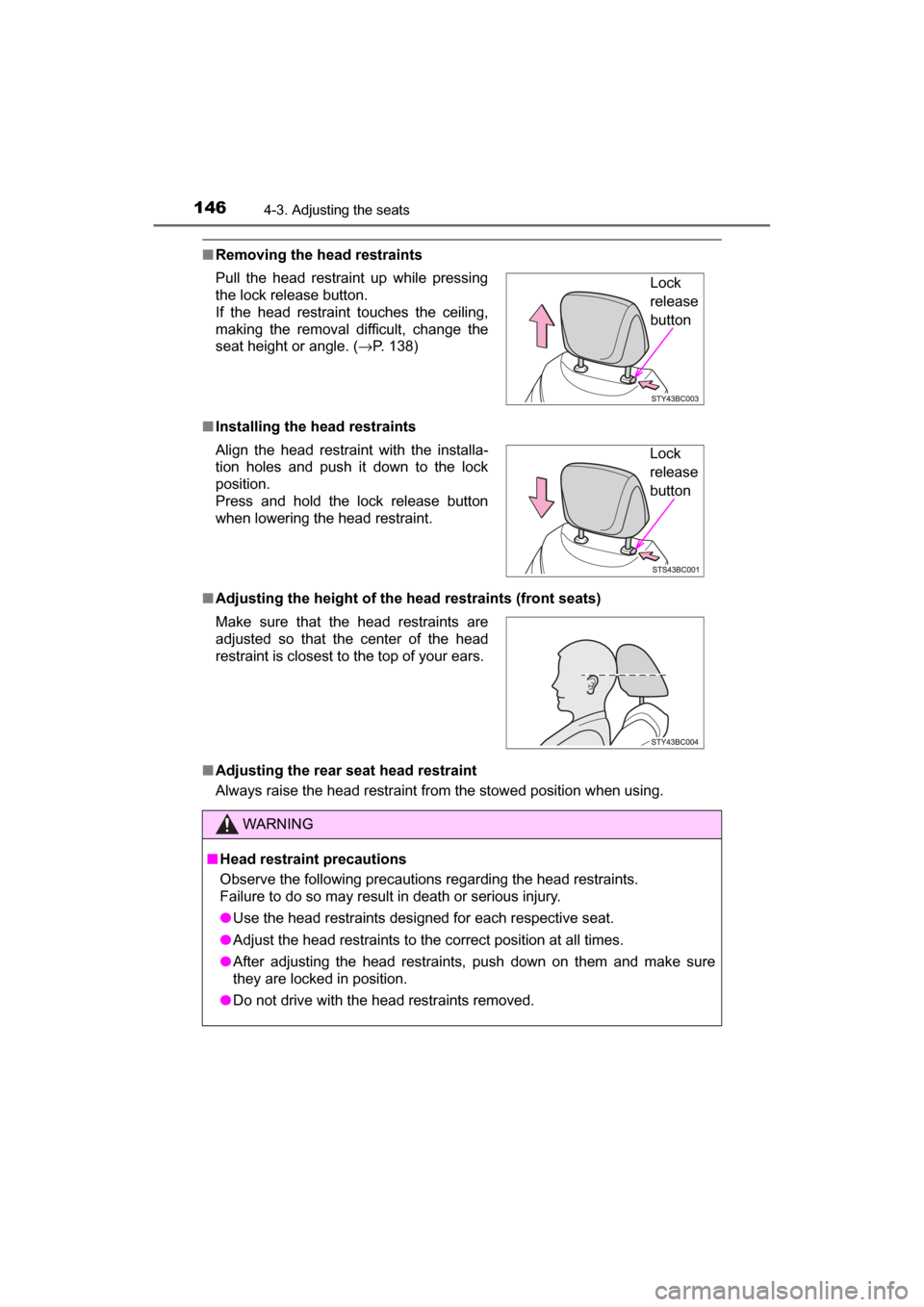
■Removing the head restraints
■ Installing the head restraints
■ Adjusting the height of the head restraints (front seats)
■ Adjusting the rear seat head restraint
Always raise the head restraint from the stowed position when using. Pull the head restraint up while pressing
the lock release button.
If the head restraint touches the ceiling,
making the removal difficult, change the
seat height or angle. ( →P. 138)
Align the head restraint with the installa-
tion holes and push it down to the lock
position.
Press and hold the lock release button
when lowering the head restraint.
Make sure that the head restraints are
adjusted so that the center of the head
restraint is closest to the top of your ears.
WARNING
■ Head restraint precautions
Observe the following precautions regarding the head restraints.
Failure to do so may result in death or serious injury.
● Use the head restraints designed for each respective seat.
● Adjust the head restraints to the correct position at all times.
● After adjusting the head restraints, push down on them and make sure
they are locked in position.
● Do not drive with the head restraints removed.
Lock
release
button
Lock
release
button
Page 149 of 464

1494-4. Adjusting the steering wheel and mirrors
4
Operation of each component
MIRAI_OM_USA_OM62023U
Inside rear view mirror
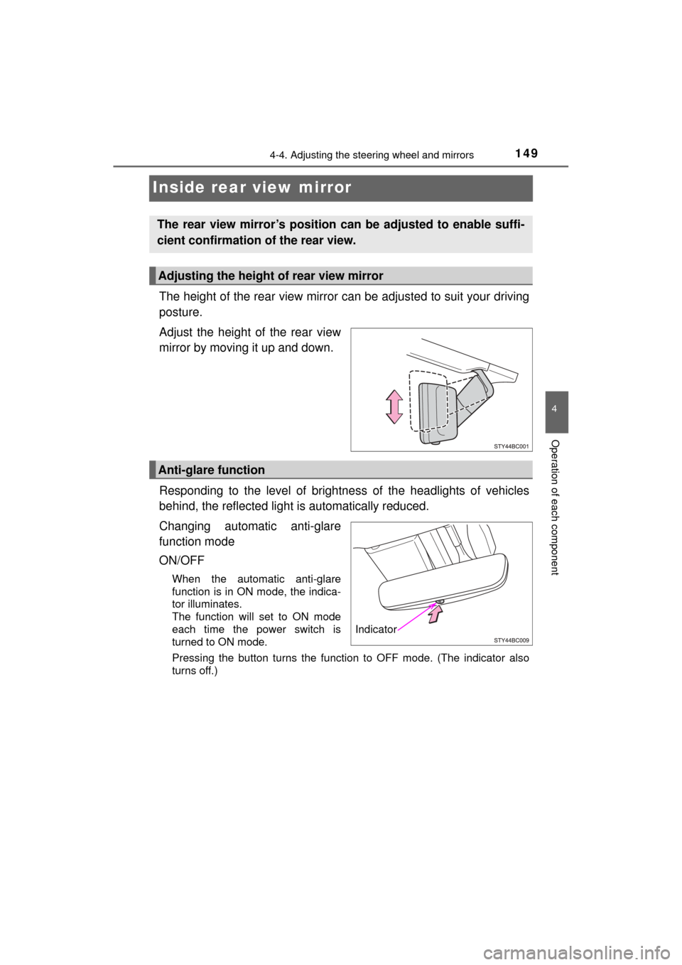
The height of the rear view mirror can be adjusted to suit your driving
posture.
Adjust the height of the rear view
mirror by moving it up and down.
Responding to the level of brightne ss of the headlights of vehicles
behind, the reflected light is automatically reduced.
Changing automatic anti-glare
function mode
ON/OFF
When the automatic anti-glare
function is in ON mode, the indica-
tor illuminates.
The function will set to ON mode
each time the power switch is
turned to ON mode.
Pressing the button turns the function to OFF mode. (The indicator also
turns off.)
The rear view mirror’s position can be adjusted to enable suffi-
cient confirmation of the rear view.
Adjusting the height of rear view mirror
Anti-glare function
Indicator