2017 SUBARU LEGACY tow
[x] Cancel search: towPage 511 of 610

Maintenance and service/Engine hood
To open the hood:
1. If the wiper blades are lifted off the
windshield, return them to their original
positions.
2. Pull the hood lock release knob under
the instrument panel.
3. Release the secondary hood lock by
moving the lever between the front grille
and the hood toward the left.
4. Lift up the hood.
To close the hood:
1. Lower the hood to a height of approxi-
mately 5.9 in (15 cm) above its closed
position and then throw it down.
2. After closing the hood, be sure the
hood is securely locked.
If this does not close the hood, release it
from a slightly higher position.
WARNING
Always check that the hood is
properly locked before you start
driving. If it is not, it might fly open
while the vehicle is moving and
block your view, which may cause
an accident and serious bodily in-
jury.
11-8
Page 514 of 610

Engine oil
CAUTION
.If the level gauge is not pulled out
easily, twist the level gauge right
and left, then pull it out. Other-
wise, you may be injured acci-
dentally straining yourself.
. Use only engine oil with the
recommended grade and vis-
cosity.
. Be careful not to spill engine oil
when adding it. If oil touches the
exhaust pipe, it may cause a bad
smell, smoke, and/or a fire. If
engine oil gets on the exhaust
pipe, be sure to wipe it off.
& Engine oil consumption
Some engine oil will be consumed while
driving. The rate of consumption can be
affected by such factors as transmission
type, driving style, terrain and tempera-
ture. Under the following conditions, oil
consumption can be increased and thus
require refilling between maintenance
intervals:
. When the engine is new and within the
break-in period .
When the engine oil is of lower quality
. When the incorrect oil viscosity is used
. When engine brakin g is employed
(repeatedly)
. When the engine is operated at high
engine speeds (for extended periods of
time)
. When the engine is operated under
heavy loads (for extended periods of time)
. When towing a trailer (Outback)
. When the engine idles for extended
periods of time
. When the vehicle is operated in stop
and go and/or heavy traffic situations
. When the vehicle is used under severe
thermal conditions
. When the vehicle accelerates and
decelerates frequently
Under these or similar conditions, you
should check your oil at least every 2nd
fuel fill-up and change your engine oil
more frequently. Different drivers in the
same car may experience different results.
If your oil consumption rate is greater than
expected, contact your authorized
SUBARU retailer who may perform a test
under controlled conditions.
& Checking the oil level
1. Park the vehicle on a level surface and
stop the engine. If you check the oil level
just after stopping the engine, wait a few
minutes for the oil to drain back into the oil
pan before checking the level.
2.5 L models
1) Oil level gauge
2) Oil filler cap
3) Oil filter
Maintenance and service/Engine oil
–CONTINUED –
11-11
Page 539 of 610
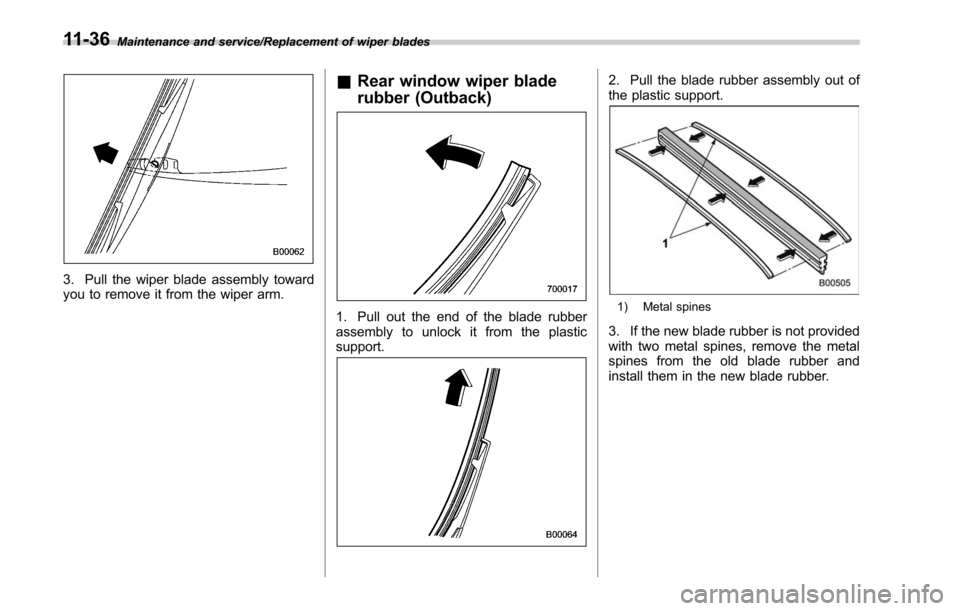
Maintenance and service/Replacement of wiper blades
3. Pull the wiper blade assembly toward
you to remove it from the wiper arm.
&Rear window wiper blade
rubber (Outback)
1. Pull out the end of the blade rubber
assembly to unlock it from the plastic
support.
2. Pull the blade rubber assembly out of
the plastic support.
1) Metal spines
3. If the new blade rubber is not provided
with two metal spines, remove the metal
spines from the old blade rubber and
install them in the new blade rubber.
11-36
Page 583 of 610
Consumer information and Reporting safety defects/Tire information
.To maximize the life of each tire
and ensure that the tires wear
uniformly, it is best to rotate the
tires every 7,500 miles (12,000 km).
Rotating the tires involves switch-
ing the front and rear tires on the
right-hand side of the vehicle and
similarly switching the front and
rear tires on the left-hand side of
the vehicle. (Each tire must be kept
on its original side of the vehicle.)
Replace any damaged or unevenly
worn tire at the time of rotation.
After tire rotation, adjust the tire
pressures and make sure the wheel
nuts are correctly tightened. For
information about the tightening
torque and tightening sequence
for the wheel nuts, refer to “Flat
tires ”F 9-5.
& Vehicle load limit –how to
determine
The load capacity of your vehicle is
determined by weight, not by avail-
able cargo space. The load limit of
your vehicle is shown on the
vehicle placard attached to the driver
’s side B-pillar. Locate the
statement “The combined weight
of occupants and cargo should
never exceed XXX kg or XXX lbs ”
on your vehicle ’s placard.
Thevehicleplacardalsoshows
seating capacity of your vehicle.
The total load capacity includes the
total weight of driver and all pas-
sengers and their belongings, any
cargo, any optional equipment such
as a trailer hitch, roof rack or bike
carrier, etc., and the tongue load of
a trailer. Therefore cargo capacity
can be calculated by the following
method.
Cargo capacity = Load limit −(total
weight of occupants + total weight
of optional equipment + tongue
load of a trailer (if applicable))
For towing capacity information and
weight limits, refer to “Trailer towing
(Outback) ”F 8-22.
! Calculating total and load ca-
pacities varying seating con-
figurations
Calculate the available load capa-
city as shown in the following
examples:
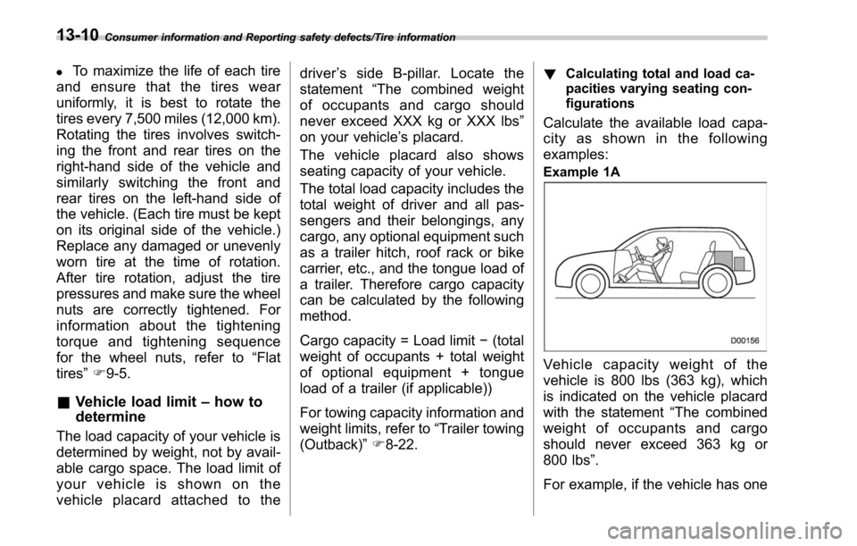
Example 1A
Vehicle capacity weight of the
vehicle is 800 lbs (363 kg), which
is indicated on the vehicle placard
with the statement “The combined
weight of occupants and cargo
should never exceed 363 kg or
800 lbs ”.
For example, if the vehicle has one
13-10
Page 584 of 610
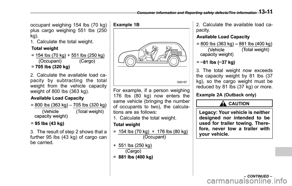
occupant weighing 154 lbs (70 kg)
plus cargo weighing 551 lbs (250
kg).
1.Calculate the total weight.
2.Calculate the available load ca-
pacity by subtracting the total
weight from the vehicle capacity
weight of 800 lbs (363 kg).
3.The result of step 2 shows that a
further 95 lbs (43 kg) of cargo can
be carried.
Example 1B
For example, if a person weighing
176 lbs (80 kg) now enters the
same vehicle (bringing the number
of occupants to two), the calcula-
tions are as follows:
1.Calculate the total weight.
2.Calculate the available load ca-
pacity.
3.The total weight now exceeds
the capacity weight by 81 lbs (37
kg), so the cargo weight must be
reduced by 81 lbs (37 kg) or more.
Example 2A (Outback only)
CAUTION
Legacy: Your vehicle is neither
designed nor intended to be
used for trailer towing. There-
fore, never tow a trailer with
your vehicle.
Consumer information and Reporting safety defects/Tire information
–CONTINUED –13-11
Page 585 of 610
Consumer information and Reporting safety defects/Tire information
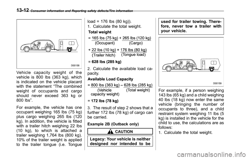
Vehicle capacity weight of the
vehicle is 800 lbs (363 kg), which
is indicated on the vehicle placard
with the statement“The combined
weight of occupants and cargo
should never exceed 363 kg or
800 lbs ”.
For example, the vehicle has one
occupant weighing 165 lbs (75 kg)
plus cargo weighing 265 lbs (120
kg). In addition, the vehicle is fitted
with a trailer hitch weighing 22 lbs
(10 kg), to which is attached a
trailer weighing 1,764 lbs (800 kg).
10% of the trailer weight is applied
to the trailer tongue (i.e. Tongue load = 176 lbs (80 kg)).
1.Calculate the total weight.
2.Calculate the available load ca-
pacity.
3.The result of step 2 shows that a
further 172 lbs (78 kg) of cargo can
be carried.
Example 2B (Outback only)
CAUTION
Legacy: Your vehicle is neither
designed nor intended to be used for trailer towing. There-
fore, never tow a trailer with
your vehicle.
For example, if a person weighing
143 lbs (65 kg) and a child weighing
40 lbs (18 kg) now enter the same
vehicle (bringing the number of
occupants to three), and a child
restraint system weighing 11 lbs (5
kg) is installed in the vehicle for the
child to use, the calculations are as
follows:
1.Calculate the total weight.
13-12
Page 587 of 610
Consumer information and Reporting safety defects/Uniform tire quality grading standards
.Tire could separate from its rim.
&Steps for Determining Cor-
rect Load Limit
1.Locate the statement “The com-
bined weight of occupants and
cargo should never exceed XXX
kg or XXX lbs. ”on your vehicle ’s
placard.
2.Determine the combined weight
of the driver and passengers that
will be riding in your vehicle.
3.Subtract the combined weight of
the driver and passengers from
XXX kg or XXX lbs.
4.The resulting figure equals the
available amount of cargo and
luggage load capacity. For exam-
ple, if the “XXX ”amount equals
1,400 lbs (635 kg) and there will be
five 150 lbs (68 kg) passengers in
your vehicle, the amount of avail-
able cargo and luggage load capa-
city is 650 lbs (1,400 −750 (5 6
150) = 650 lbs).
5.Determine the combined weight
of luggage and cargo being loaded on the vehicle. That weight may not
safely exceed the available cargo
and luggage load capacity calcu-
lated in Step 4.
6.If your vehicle will be towing a
trailer, load from your trailer will be
transferred to your vehicle. Consult
this manual to determine how this
reduces the available cargo and
luggage load capacity of your ve-
hicle.
Uniform tire quality grading
standards
This information indicates the rela-
tive performance of passenger car
tires in the area of treadwear,
traction, and temperature resis-
tance. This is to aid the consumer
in making an informed choice in the
purchase of tires.
Quality grades can be found where
applicable on the tire sidewall be-
tween tread shoulder and maxi-
mum section width. For example:
Treadwear 200 Traction AA Tem-
perature A
The quality grades apply to new
pneumatic tires for use on passen-
ger cars. However, they do not
apply to deep tread, winter type
snow tires, space-saver or tempor-
ary use spare tires, tires with
nominal rim diameters of 12 inches
or less, or to some limited produc-
tion tires.
All passenger car tires must con-
13-14
Page 595 of 610
14-6Index
H
Hands-free phone system........................................... 5-71
Hazard warning flasher ........................................... 3-8, 9-2
Head restraint adjustment Front seat ............................................................... 1-8
Rear seat .............................................................. 1-14
Headlight .................................................................. 3-47
Beam leveler ......................................................... 3-54
Bulb wattage ....................................................... 12-14
Control switch ........................................................ 3-46
Flasher ................................................................. 3-53
Indicator light ......................................................... 3-32
Welcome lighting function ....................................... 3-48
Heated Steering Wheel system .................................... 3-83
High beam assist function ........................................... 3-49
Indicator light ......................................................... 3-31
Warning indicator ................................................... 3-31
High beam indicator light ............................................ 3-31
High/low beam change (dimmer) .................................. 3-49
Hill descent control ..................................................... 7-40
Indicator. ............................................................... 3-32
Hill Holder ................................................................. 7-45
Indicator light ......................................................... 3-22
Switch .................................................................. 7-46
Hill start assist ........................................................... 7-48
To activate/deactivate ............................................. 7-50
HomeLink
®........................................................ 3-63, 3-69
Hook Coat ..................................................................... 6-12
Convenient ............................................................ 6-14
Convenient tie-down ............................................... 6-19 Shopping bag
........................................................ 6-13
Towing and tie-down ............................................... 9-14
Horn ........................................................................\
. 3-83
Hose and connections ............................................... 11-14
I
Ignition switch ............................................................. 3-4
Light ...................................................................... 3-5
Illumination brightness control ...................................... 3-55
Immobilizer ................................................................. 2-4
Indicator light (security indicator light) ........................ 3-30
Indicator light BSD/RCTA OFF ..................................................... 3-32
Cruise control ........................................................ 3-31
Cruise control set ................................................... 3-32
Door open ............................................................. 3-23
Electronic parking brake .......................................... 3-21
Front fog light ......................................................... 3-32
Headlight ............................................................... 3-32
High beam ............................................................. 3-31
High beam assist .................................................... 3-31
Hill descent control ................................................. 3-32
Hill Holder ............................................................. 3-22
Immobilizer ............................................................ 3-30
Security ................................................................. 3-30
Select lever/Gear position ........................................ 3-31
Steering responsive fog lights OFF ... ........................ 3-32
Turn signal ............................................................ 3-31
Vehicle Dynamics Control OFF ................................. 3-25
Vehicle Dynamics Control operation .. ........................ 3-24
X-mode ................................................................. 3-32