2017 SUBARU LEGACY driver seat adjustment
[x] Cancel search: driver seat adjustmentPage 37 of 610

Seat, seatbelt and SRS airbags/Front seats
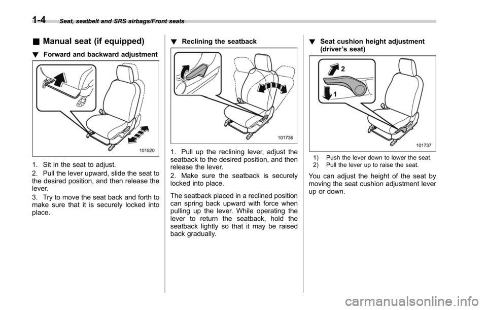
&Manual seat (if equipped)
! Forward and backward adjustment
1. Sit in the seat to adjust.
2. Pull the lever upward, slide the seat to
the desired position, and then release the
lever.
3. Try to move the seat back and forth to
make sure that it is securely locked into
place. !
Reclining the seatback
1. Pull up the reclining lever, adjust the
seatback to the desired position, and then
release the lever.
2. Make sure the seatback is securely
locked into place.
The seatback placed in a reclined position
can spring back upward with force when
pulling up the lever. While operating the
lever to return the seatback, hold the
seatback lightly so that it may be raised
back gradually. !
Seat cushion height adjustment
(driver ’s seat)1) Push the lever down to lower the seat.
2) Pull the lever up to raise the seat.
You can adjust the height of the seat by
moving the seat cushion adjustment lever
up or down.
1-4
Page 41 of 610

Seat, seatbelt and SRS airbags/Front seats
NOTE
.If the registered seat position cannot
be retrieved after performing the pre-
vious procedures, try the following
procedures.
(1) Press the “SET ”button on the
driver ’s door.
(2) Press the “
”button on the
access key or touch the door lock
sensor to lock the doors.
(3) Perform the prior procedures
again.
. If the keyless access function is
disabled, the seat position cannot be
retrieved by gripping the driver ’s door
handle. However, the seat position can
still be retrieved by pressing the “
”
button on the access key. For informa-
tion about how to enable/disable the
keyless access function, refer to “Dis-
abling keyless access function” F2-18.
. If a new position is registered for the
same access key, the previously regis-
tered seat position is deleted.
! Clearing the registered seat
position with access key
1. Close the driver ’s door.
2. While holding the access key and
pressing the “SET”button, press the “
”
button on the access key. A chirp will sound, and the registered seat
position will be cleared.
&
Head restraint adjustment
WARNING
. Never drive the vehicle with the
head restraints removed because
they are designed to reduce the
risk of serious neck injury in the
event that the vehicle is struck
from the rear. Also, never install
the head restraints the opposite
way around. Doing so will pre-
vent the head restraints from
functioning as intended. There-
fore, when you remove the head
restraints, you must reinstall all
head restraints correctly to pro-
tect vehicle occupants.
. All occupants, including the dri-
ver, should not operate a vehicle
or sit in a vehicle ’s seat until the
head restraints are placed in their
proper positions in order to mini-
mize the risk of neck injury in the
event of a crash.
Both the driver ’s seat and front passen-
ger ’s seat are equipped with head re-
straints. Both head restraints are adjusta-
ble in the following ways. !
Head restraint height adjustment
1) Head restraint
2) Release button
To raise:
Pull the head restraint up.
To lower:
Push the head restraint down while
pressing the release button on the top of
the seatback.
To remove:
While pressing the release button, pull out
the head restraint.
To install:
Install the head restraint into the holes that
are located on the top of the seatback until
the head restraint locks. Press and hold
the release button to lower the head
restraint.
1-8
Page 379 of 610

Starting and operating/Preparing to drive
.A vehiclefails the OBDII inspection if
the “CHECK ENGINE ”warning light is not
properly operating (light is illuminated or is
not working due to a burned out bulb) or
there is one or more diagnostic trouble
codes stored in the vehicle’ s computer.
. A state emission inspection may reject
(not pass or fail) a vehicle if the number of
OBDII system readiness monitors “NOT
READY ”is greater than one. If the
vehicle’ s battery has been recently re-
placed or disconnected, the OBDII system
inspection may indicate that the vehicle is
not ready for the emission test. Under this
condition, the vehicle driver should be
instructed to drive his/her vehicle for a few
days to reset the readiness monitors and
return for an emission re-inspection.
. Owners of rejected or failing vehicles
should contact their SUBARU Dealer for
service.
Some states still use dynamometers in
their emission inspection program. A
dynamometer is a treadmill or roller-like
testing device that allows your vehicle ’s
wheels to turn while the vehicle remains in
one place. Prior to your vehicle being put
on a dynamometer, tell your emission
inspector
not to place your SUBARU
AWD vehicle on a two-wheel dynam-
ometer. Otherwise, serious transmis-
sion damage will result. The U.S. Environmental Protection
Agency (EPA) and states using two-wheel
dynamometers in their emission testing
program have EXEMPTED SUBARU
AWD vehicles from the portion of the
testing program that involves a two-wheel
dynamometer. There are some states that
use four-wheel dynamometers in their
testing program. When properly used, this
equipment should not damage a SUBARU
AWD vehicle.
Under no circumstances should the rear
wheels be jacked off the ground, nor
should the driveshaft be disconnected for
state emission testing.
Preparing to drive
You should perform the following checks
and adjustments every day before you
start driving.
1. Check that all windows, mirrors, and
lights are clean and unobstructed.
2. Check the appearance and condition
of the tires. Also check tires for proper
inflation.
3. Look under the vehicle for any sign of
leaks.
4. Check that the hood, trunk (Legacy)
and rear gate (Outback) are fully closed.
5. Check the adjustment of the seat.
6. Check the adjustment of the inside
and outside mirrors.
7. Fasten your seatbelt. Check that your
passengers have fastened their seatbelts.
8. Check the operation of the warning
and indicator lights when the ignition
switch is turned to the
“ON”position.
9. Check the gauges, indicator and warn-
ing lights after starting the engine.
10. Check that no small animals enter the
engine compartment.
7-8
Page 594 of 610

Winter.................................................................... 8-8
E
ECO gauge ............................................................... 3-12
Electrical system ........................................................ 12-9
Electronic Brake Force Distribution (EBD) system .......... 7-34
Warning ................................................................ 3-20
Electronic parking brake. ............................................. 7-43
Automatic release function by accelerator pedal ......... 7-45
Hill Holder ............................................................. 7-45
Indicator light ......................................................... 3-21
Warning ........................................................ 3-21, 7-47
Emergency Locking Retractor (ELR) ............................. 1-17
Engine Compartment overview ........................................... 11-9
Coolant ........................................................ 11-15, 12-8
Exhaust gas (carbon monoxide) ............................. 6, 8-2
Hood .................................................................... 11-7
Low oil level warning indicator ................................. 3-17
Oil............................................................... 11-11, 12-4
Overheating .......................................................... 9-13
Starting & stopping ........................................... 7-9, 7-12
Event data recorder ......................................................... 9
Exterior care .............................................................. 10-2
F
Flat tires ..................................................................... 9-5
Floor mat .................................................................. 6-15
Fluid level Brake .................................................................. 11-20
Clutch .................................................................. 11-21 Continuously variable transmission
......................... 11-19
Fog light Bulb .......................................................... 11-42, 12-14
Indicator light ......................................................... 3-32
Steering responsive fog lights system ....................... 3-56
Switch ................................................................... 3-56
Front Differential gear oil ........................................ 11-19, 12-7
Seatbelt pretensioners ............................................ 1-24
Side marker light .................................................. 11-42
Turn signal light .................................................... 11-42
Front seats ................................................................. 1-2
Forward and backward adjustment ............................ 1-4
Head restraint adjustment ......................................... 1-8
Memory function ...................................................... 1-6
Power seat ............................................................. 1-5
Reclining ................................................................ 1-4
Seat height adjustment (driver ’s seat) ........................ 1-4
Fuel ........................................................................\
... 7-3
Consumption indicator ............................................. 3-38
Economy hints ........................................................ 8-2
Filler lid and cap ...................................................... 7-4
Gauge ................................................................... 3-11
Requirements ................................................. 7-3, 12-3
Fuses .....................................................................
11-38
Fuses and circuits .................................................... 12-10
G
GAWR (Gross Axle Weight Rating) .. ............................. 8-14
Glove box ................................................................... 6-6
GVWR (Gross Vehicle Weight Rating) ........................... 8-14
Index14-5