Page 14 of 634

&Noise from under the vehicle
NOTE
You may hear a noise from under the
vehicle approximately 5 to 10 hours
after the engine is turned off. However,
this does not indicate a malfunction.
This noise is caused by the operation
of the fuel evaporation leakage check-
ing system and the operation is normal.
The noise will stop after approximately
15 minutes.
& Event data recorder
This vehicle is equipped with an event
data recorder (EDR). The main purpose of
an EDR is to record, in certain crash or
near crash-like situations, such as an air
bag deployment or hitting a road obstacle,
data that will assist in understanding how
a vehicle’ s systems performed. The EDR
is designed to record data related to
vehicle dynamics and safety systems for
a short period of time, typically 30 seconds
or less. The EDR in this vehicle is
designed to record such data as:
. How various systems in your vehicle
were operating;
. Whether or not the driver and passen-
ger safety belts were buckled/fastened;
. Howfar(ifatall)thedriverwas
depressing the accelerator and/or brake pedal; and,
.
How fast the vehicle was traveling.
These data can help provide a better
understanding of the circumstances in
which crashes and injuries occur. NOTE:
EDR data are recorded by your vehicle
only if a non-trivial crash situation occurs;
no data are recorded by the EDR under
normal driving conditions and no personal
data (e.g., name, gender, age, and crash
location) are recorded. However, other
parties, such as law enforcement, could
combine the EDR data with the type of
personally identifying data routinely ac-
quired during a crash investigation.
To read data recorded by an EDR, special
equipment is required, and access to the
vehicle or the EDR is needed. In addition
to the vehicle manufacturer, other parties,
such as law enforcement, that have the
special equipment, can read the informa-
tion if they have access to the vehicle or
the EDR.
9
Page 24 of 634
&Combination meter
! U.S.-spec. models (type A)
The illustration above is a typical example. For some models, the combination meter
may be slightly different than that shown in the illustration.
1) Tachometer (page 3-11)
2) Select lever/gear position indicator
(page 3-31)
3) Trip meter and odometer (page 3-10)
4) Speedometer (page 3-10)
5) Information display selection knob (page 3-34)
6) Fuel gauge (page 3-12)
7) X-mode (if equipped) (page 7-42)/SI- DRIVE (if equipped) (page 7-32)
8) Trip meter A/B selection and trip meter reset knob (page 3-10)
–CONTINUED –
19
Page 25 of 634
!U.S.-spec. models (type B)
The illustration above is a typical example. For some models, the combination meter
may be slightly different than that shown in the illustration.
1) Tachometer (page 3-11)
2) Multi information display (page 3-39)
3) Fuel gauge (page 3-12)
4) Select lever/gear position indicator
(page 3-31)
5) Speedometer (page 3-10)
6) Trip meter A/B selection and trip meter reset knob (page 3-10)
7) Trip meter and odometer (page 3-10)
20
Page 26 of 634
!Canada-spec. and Mexico-spec. models (type A)
The illustration above is a typical example. For some models, the combination meter
may be slightly different than that shown in the illustration.
1) Tachometer (page 3-11)
2) Trip meter and odometer (page 3-10)
3) Select lever/gear position indicator
(page 3-31)
4) Speedometer (page 3-10)
5) Information display selection knob (page 3-34)
6) ECO gauge (Mexico-spec. models) (page 3-12)
7) Fuel gauge (page 3-12)
8) Trip meter A/B selection and trip meter reset knob (page 3-10)
–CONTINUED –
21
Page 27 of 634
!Canada-spec. and Mexico-spec. models (type B)
The illustration above is a typical example. For some models, the combination meter
may be slightly different than that shown in the illustration.
1) Tachometer (page 3-11)
2) Multi information display (page 3-39)
3) Fuel gauge (page 3-12)
4) Select lever/gear position indicator
(page 3-31)
5) Speedometer (page 3-10)
6) Trip meter A/B selection and trip meter reset knob (page 3-10)
7) Trip meter and odometer (page 3-10)
22
Page 163 of 634

Instruments and controls/Meters and gauges
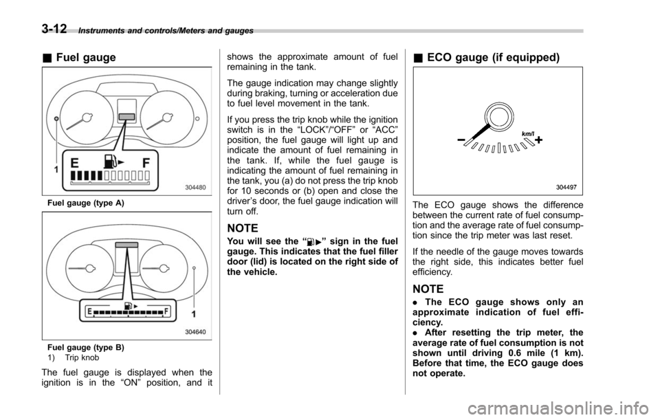
&Fuel gauge
Fuel gauge (type A)
Fuel gauge (type B)
1) Trip knob
The fuel gauge is displayed when the
ignition is in the “ON”position, and it shows the approximate amount of fuel
remaining in the tank.
The gauge indication may change slightly
during braking, turning or acceleration due
to fuel level movement in the tank.
If you press the trip knob while the ignition
switch is in the
“LOCK”/ “OFF”or “ACC ”
position, the fuel gauge will light up and
indicate the amount of fuel remaining in
the tank. If, while the fuel gauge is
indicating the amount of fuel remaining in
the tank, you (a) do not press the trip knob
for 10 seconds or (b) open and close the
driver ’s door, the fuel gauge indication will
turn off.
NOTE
You will see the “”sign in the fuel
gauge. This indicates that the fuel filler
door (lid) is located on the right side of
the vehicle.
& ECO gauge (if equipped)
The ECO gauge shows the difference
between the current rate of fuel consump-
tion and the average rate of fuel consump-
tion since the trip meter was last reset.
If the needle of the gauge moves towards
the right side, this indicates better fuel
efficiency.
NOTE
. The ECO gauge shows only an
approximate indication of fuel effi-
ciency.
. After resetting the trip meter, the
average rate of fuel consumption is not
shown until driving 0.6 mile (1 km).
Before that time, the ECO gauge does
not operate.
3-12
Page 164 of 634

Warning and indicator lights
Several of the warning and indicator lights
illuminate when the ignition switch is
initially turned to the“ON”position. This
permits checking the operation of the
bulbs.
Apply the parking brake and turn the
ignition switch to the “ON”position. For
the system check, several of the following
lights illuminate and then turn off after
several seconds or after the engine has
started.
: Seatbelt warning light (The seatbelt warning light turns off
only when the driver fastens the
seatbelt.)
: Front passenger ’s seatbelt warning
light
(The seatbelt warning light turns off
only when the front seat passenger
fastens the seatbelt.)
: SRS airbag system warning light
ON /
: Front passenger ’s frontal airbag
ON indicator light
/: Front passenger ’s frontal airbag
OFF indicator light
: CHECK ENGINE warning light/Mal- function indicator light
: Coolant temperature low indicator light/Coolant temperature high warn-
ing light
: Charge warning light
: Oil pressure warning light
: Engine low oil level warning light*
: Windshield washer fluid warning light*
: AT OIL TEMP warning light(CVT models)
: Low tire pressure warning light(U.S.-spec. models)
/: ABS warning light
/: Brake system warning light
: Low fuel warning light
: Hill start assist warning light/Hill startassist OFF indicator light
: Door open warning light
: AWD warning light (CVT models)
: Power steering warning light
: Vehicle Dynamics Control warning light/Vehicle Dynamics Control opera-
tion indicator light
: Vehicle Dynamics Control OFF indica-tor light
: Cruise control indicator light(if equipped)
: Cruise control set indicator light(if equipped)
: Headlight indicator light (if equipped)
: Automatic headlight beam leveler warning light (if equipped)
: Steering Responsive Headlight warn-ing light/Steering Responsive Head-
light OFF indicator light (if equipped)*
: High beam assist indicator light (if equipped)
: Access key warning light
(if equipped)
: X-mode indicator light (if equipped)
: Hill descent control indicator light (if equipped)*
*: Applies to models with type A combina- tion meter.
If any lights fail to illuminate, it indicates a
burned-out bulb or a malfunction of the
corresponding system.
Consult your authorized SUBARU dealer
for repair.
Instruments and controls/Warning and indicator lights
–CONTINUED –3-13
Page 186 of 634

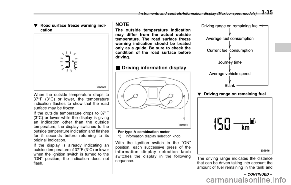
!Road surface freeze warning indi-
cation
When the outside temperature drops to
378F(3 8C) or lower, the temperature
indication flashes to show that the road
surface may be frozen.
If the outside temperature drops to 37 8F
(3 8C) or lower while the display is giving
an indication other than the outside
temperature, the display switches to the
outside temperature indication and flashes
for 5 seconds before returning to its
original indication.
If the display is already indicating an
outside temperature of 37 8F(3 8C) or lower
when the ignition switch is turned to the
“ ON ”position, the indication does not
flash.
NOTE
The outside temperature indication
may differ from the actual outside
temperature. The road surface freeze
warning indication should be treated
only as a guide. Be sure to check the
condition of the road surface before
driving.
& Driving information display
For type A combination meter
1) Information display selection knob
Withtheignitionswitchinthe“ ON”
position, each successive press of the
information display selection knob
switches the display in the following
sequence.
! Driving range on remaining fuel
The driving range indicates the distance
that can be driven taking into account the
amount of fuel remaining in the tank and
Instruments and controls/Information display (Mexico –spec. models)
–CONTINUED –3-35