2017 SUBARU FORESTER fog light
[x] Cancel search: fog lightPage 281 of 634

Climate control/Manual climate control operation
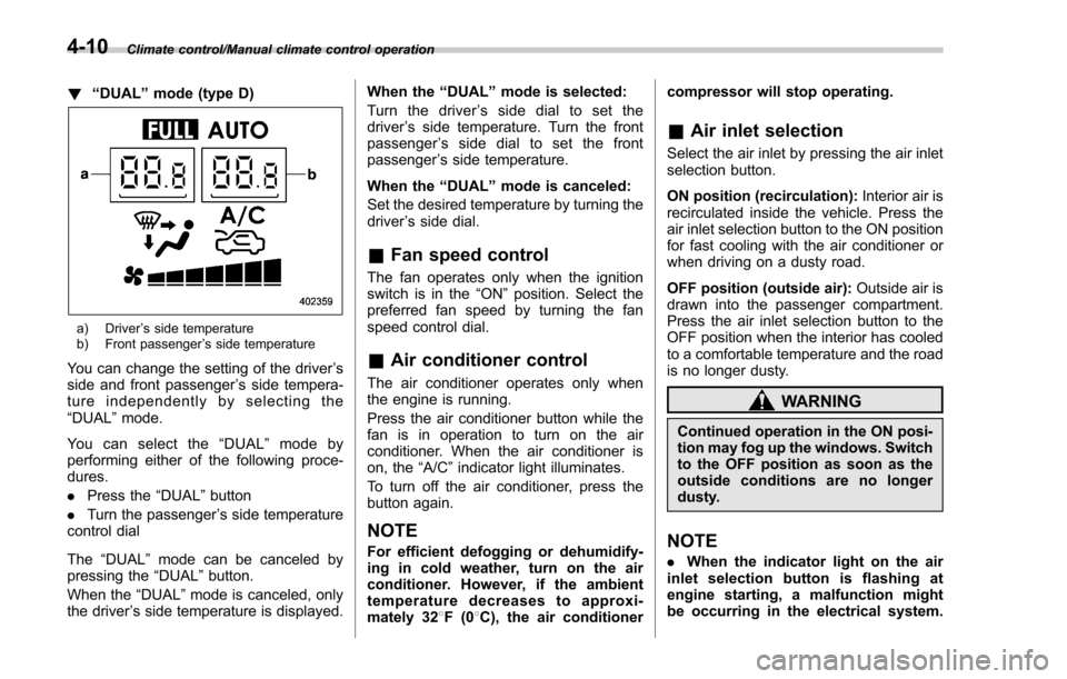
!“DUAL ”mode (type D)
a) Driver ’s side temperature
b) Front passenger ’s side temperature
You can change the setting of the driver ’s
side and front passenger ’s side tempera-
ture independently by selecting the
“DUAL ”mode.
You can select the “DUAL ”mode by
performing either of the following proce-
dures.
. Press the “DUAL”button
. Turn the passenger ’s side temperature
control dial
The “DUAL ”mode can be canceled by
pressing the “DUAL”button.
When the “DUAL”mode is canceled, only
the driver ’s side temperature is displayed. When the
“DUAL ”mode is selected:
Turn the driver ’s side dial to set the
driver ’s side temperature. Turn the front
passenger ’s side dial to set the front
passenger ’s side temperature.
When the “DUAL ”mode is canceled:
Set the desired temperature by turning the
driver ’s side dial.
& Fan speed control
The fan operates only when the ignition
switch is in the “ON”position. Select the
preferred fan speed by turning the fan
speed control dial.
& Air conditioner control
The air conditioner operates only when
the engine is running.
Press the air conditioner button while the
fan is in operation to turn on the air
conditioner. When the air conditioner is
on, the “A/C ”indicator light illuminates.
To turn off the air conditioner, press the
button again.
NOTE
For efficient defogging or dehumidify-
ing in cold weather, turn on the air
conditioner. However, if the ambient
temperature decreases to approxi-
mately 32 8F(0 8C), the air conditioner compressor will stop operating.
&
Air inlet selection
Select the air inlet by pressing the air inlet
selection button.
ON position (recirculation): Interior air is
recirculated inside the vehicle. Press the
air inlet selection button to the ON position
for fast cooling with the air conditioner or
when driving on a dusty road.
OFF position (outside air): Outside air is
drawn into the passenger compartment.
Press the air inlet selection button to the
OFF position when the interior has cooled
to a comfortable temperature and the road
is no longer dusty.
WARNING
Continued operation in the ON posi-
tion may fog up the windows. Switch
to the OFF position as soon as the
outside conditions are no longer
dusty.
NOTE
. When the indicator light on the air
inlet selection button is flashing at
engine starting, a malfunction might
be occurring in the electrical system.
4-10
Page 413 of 634

Starting and operating/Starting and stopping the engine (models without push–button start system)
. When starting the engine, be sure
to sit in the driver ’s seat (except
when using the remote engine
start system).
NOTE
. Avoid rapid racing and rapid accel-
eration immediately after the engine
has started.
. For a short time after the engine has
started, the engine speed is kept high.
When the warm-up is completed, the
engine speed lowers automatically.
. On rare occasions, it may be difficult
to start the engine depending on the
fuel and the usage condition (repeated
driving of a distance in which the
engine has not warmed up sufficiently).
In such a case, it is recommended that
you change to a different brand of fuel.
. On rare occasions, transient knock-
ing may be heard from the engine when
the accelerator is operated rapidly
such as a rapid start-up and a rapid
acceleration. This is not a malfunction.
. The engine starts more easily when
the headlights, air conditioner and rear
window defogger are turned off.
. After the engine starts, the engine
speed will be kept high until the engine
has warmed up sufficiently. !
MT models
1. Apply the parking brake.
2. Turn off unnecessary lights and ac-
cessories.
3. Depress the clutch pedal to the floor
and shift the shift lever into neutral. Hold
the clutch pedal to the floor while starting
the engine.
The starter motor will only operate when
the clutch pedal is depressed fully to the
floor.
4. Turn the ignition switch to the “ON”
position and check the operation of the
warning and indicator lights. Refer to
“Warning and indicator lights ”F 3-13.
5. Turn the ignition switch to the “START”
position without depressing the accelera-
tor pedal. Release the key immediately
after the engine has started.
If the engine does not start, try the
following procedure.
(1) Turn the ignition switch to the
“OFF ”position and wait for at least
10 seconds. After checking that the
parking brake is firmly set, turn the
ignition switch to the “START”position
while depressing the accelerator pedal
slightly (approximately a quarter of the
full stroke). Release the accelerator
pedal as soon as the engine starts.
(2) If this fails to start the engine, turn the ignition switch back to the
“OFF”
position and wait for at least 10
seconds. Then fully depress the accel-
erator pedal and turn the ignition
switch to the “START”position. If the
engine starts, quickly release the
accelerator pedal.
(3) If this fails to start the engine, turn
the ignition switch again to the “OFF”
position. After waiting for 10 seconds
or longer, turn the ignition switch to the
“START ”position without depressing
the accelerator pedal.
(4) If the engine still does not start,
contact your nearest SUBARU dealer
for assistance.
6. Confirm that all warning and indicator
lights have turned off after the engine has
started. The fuel injection system auto-
matically lowers the idle speed as the
engine warms up.
! CVT models
1. Apply the parking brake.
2. Turn off unnecessary lights and ac-
cessories.
3. Shift the select lever to the “P”or “N
”
position (preferably the “P”position).
The
starter motor will only operate when
the select lever is at the “P”or “N”position.
4. Turn the ignition switch to the “ON”
7-10
Page 464 of 634

operation and the BSD/RCTA warning
indicator will disappear. However, if the
BSD/RCTA warning indicator has ap-
peared for a prolonged time, have the
system inspected at a SUBARU dealer
as soon as possible.
.The detectability of the radar sen-
sors is restricted. The BSD/RCTA de-
tection may be impaired and the sys-
tem may not operate properly under the
following conditions.
–When the rear bumper around
the radar sensors is distorted
– When ice, snow or mud adheres
to the rear bumper surface around
the radar sensors
– When stickers, etc. are affixed on
the areas of the radar sensors on
the rear bumper
– During adverse weather condi-
tions such as rain, snow or fog
– When driving on wet roads such
as snow-covered roads and
through puddles
. The radar sensors may not detect or
may have difficulty detecting the fol-
lowing.
–Small motorcycles, bicycles, pe-
destrians, stationary objects on the
road or road side, etc.
– Vehicles with body shapes that
the radar may not reflect (vehicles with a low body height such as
sports cars or a trailer with no
cargo)
–
Vehicles that are not approach-
ing your vehicle even though they
are in the detection area (either on a
neighboring lane to the rear or
beside your vehicle when rever-
sing) (The system determines the
presence of approaching vehicles
based on data detected by the radar
sensors.)
– Vehicles traveling at significantly
different speeds
– Vehicles driving in parallel at
almost the same speed as your
vehicle for a prolonged time
– Oncoming vehicles
– Vehicles in a lane beyond the
neighboring lane
– Vehicles travelling at a signifi-
cantly lower speed that you are
trying to overtake
. On a road with extremely narrow
lanes, the system may detect vehicles
driving in a lane next to the neighbor-
ing lane.& BSD/RCTA approach indica-
tor light/warning buzzer
While the BSD/RCTA is active, the follow-
ing item(s) will operate to alert the driver.
. The BSD/RCTA approach indicator
light (when there are vehicles in the
neighboring lanes)
. The BSD/RCTA approach indicator
light and warning buzzer (when a vehicle
is approaching from the left or right side
while reversing)
! BSD/RCTA approach indicator light
BSD/RCTA approach indicator light
It is mounted in each side of the outside
mirrors and will illuminate when a vehicle
approaching from behind is detected. If an
indicator light is illuminated and the turn
Starting and operating/BSD/RCTA
–CONTINUED –7-61
Page 472 of 634

Parts attached to the rear bumper
near the sonar sensor– Commercial electronic parts (fog
light, fender pole, radio antenna) or
commercial attachment parts (trai-
ler hitch, bicycle carrier, bumper
guard) are attached
– Parts that emit high frequency
sound, such as a horn or speaker,
are attached
Vehicle conditions – The vehicle is significantly in-
clined
– The ground clearance is signifi-
cantly reduced due to the vehicle ’s
loading condition, etc.
– When the sonar sensor is mis-
aligned due to a collision or an
accident
Surrounding environment – A cloth banner, flag, hanging
branch or railroad crossing bars
are present in the reversing direc-
tion
– When reversing on a gravel or
grassy area
– When reversing in an area where
objects or walls are adjacent to the
vehicle such as narrow tunnels,
narrow bridges, narrow roads or narrow garages
–
Wheel tracks or a hole is present
in the ground of the reversing
direction
– When reversing over a drainage
cover (grate cover)
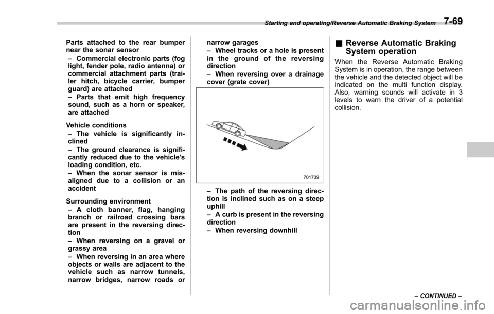
– The path of the reversing direc-
tion is inclined such as on a steep
uphill
– A curb is present in the reversing
direction
– When reversing downhill
& Reverse Automatic Braking
System operation
When the Reverse Automatic Braking
System is in operation, the range between
the vehicle and the detected object will be
indicated on the multi function display.
Also, warning sounds will activate in 3
levels to warn the driver of a potential
collision.
Starting and operating/Reverse Automatic Braking System
–CONTINUED –7-69
Page 533 of 634

Maintenance and service
Tire replacement.............................................. 11-29
Wheel replacement ........................................... 11-30
Aluminum wheels............................................. 11-30
Windshield washer fluid .................................. 11-30
Replacement of wiper blades .......................... 11-32
Windshield wiper blade assembly ..................... 11-33
Windshield wiper blade rubber ......................... 11-33
Rear window wiper blade assembly .................. 11-34
Rear window wiper blade rubber ....................... 11-35
Battery............................................................... 11-36
Fuses ................................................................ 11-37
Installation of accessories ............................... 11-38 Replacing bulbs
............................................... 11-39
Headlights (models with LED headlights) .......... 11-39
Headlights (models with halogen headlights) .................................................... 11-39
Front turn signal light, front side marker light and parking light ........................................... 11-41
Front fog light (if equipped) .............................. 11-42
Rear combination lights ................................... 11-42
License plate light ........................................... 11-44
Other bulbs ..................................................... 11-44
Replacing key battery ...................................... 11-44Replacing battery of access key ....................... 11-45
Replacing transmitter battery ........................... 11-46
Page 569 of 634

Maintenance and service/Installation of accessories
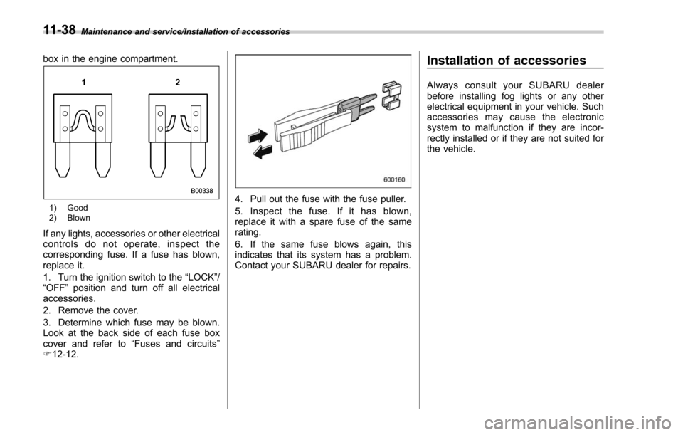
box in the engine compartment.
1) Good
2) Blown
If any lights, accessories or other electrical
controls do not operate, inspect the
corresponding fuse. If a fuse has blown,
replace it.
1. Turn the ignition switch to the“LOCK” /
“ OFF ”position and turn off all electrical
accessories.
2. Remove the cover.
3. Determine which fuse may be blown.
Look at the back side of each fuse box
cover and refer to “Fuses and circuits”
F 12-12.
4. Pull out the fuse with the fuse puller.
5. Inspect the fuse. If it has blown,
replace it with a spare fuse of the same
rating.
6. If the same fuse blows again, this
indicates that its system has a problem.
Contact your SUBARU dealer for repairs.
Installation of accessories
Always consult your SUBARU dealer
before installing fog lights or any other
electrical equipment in your vehicle. Such
accessories may cause the electronic
system to malfunction if they are incor-
rectly installed or if they are not suited for
the vehicle.
11-38
Page 573 of 634

Maintenance and service/Replacing bulbs
Front turn signal light (models with LED
headlight)
Front side marker light and parking light
(models with halogen headlight)
1) Front side marker light
2) Parking light
Front side marker light (models with LED
headlight)
1) Front side marker light
2. Turn the socket counterclockwise and
pull it out.
3. Pull out the bulb from the socket and
replace the bulb with a new one.
4. To install the socket to the headlight
assembly, turn it clockwise until it clicks.
5. Install the electrical connector to the
clip.
&Front fog light (if equipped)
It may be difficult to replace the bulbs.
Have the bulbs replaced by your SUBARU
dealer if necessary.
&Rear combination lights
NOTE
The stop light is an LED (Light Emitting
Diode) type. Consult your SUBARU
dealer for replacement.
1. Using a Phillips screwdriver, remove
the upper and lower screws that secure
the rear combination light assembly.
11-42
Page 592 of 634

Fuse
panel Fuse
rating Circuit
15 10A .Luggage light
. Keyless unit
16 7.5A .Illumination
17 15A .Seat heaters
18 10A .Backup light
19 7.5A .Wiper relay
20 10A .Accessory power outlet
(instrument panel)
21 10A .Starter relay
22 7.5A .Air conditioner
. Rear window defogger
relay coil
23 Empty
24 10A .Audio unit
. Navigation system (if
equipped)
25 15A .SRS airbag system
26 Empty
27 15A .Blower fan
28 15A .Blower fan
29 15A .Fog light
30 Empty Fuse
panel Fuse
rating Circuit
31 7.5A .Auto air conditioner unit
. Integrated unit
32 7.5A .Clutch switch
. Steering lock control
unit
33 7.5A .Vehicle Dynamics Con-
trol unit Specifications/Fuses and circuits
–CONTINUED –
12-13