Page 89 of 328

Self-help
–
Ac
celerate with particular care and cau-
tion.
– Avoid sudden braking and manoeuvres.
– Brake earlier than usual and more
smoothly. CAUTION
● To av
oid damaging the vehicle, for example
the paint, remove and replace the lid and
towing eye carefully.
● Unburnt fuel could enter the catalytic con-
ver
ter and damage it during towing. Indications for tow-starting
Vehicle's should not generally be tow-star-
t
ed.
The jump start should be used instead
››› page 58.
For technical reasons, towing the following
vehicles is not allowed:
● Vehicles with an automatic gearbox.
● If the vehicle battery is discharged, be-
cau
se in vehicles with the Keyless Access
locking and ignition system the steering re-
mains locked and the electronic parking
brake cannot be deactivated nor can the elec-
tronic lock of the steering column be re-
leased if they are activated. ●
If the b
attery is flat, it is possible that the
engine control units may not operate correct-
ly.
However, if the vehicle must absolutely be
tow-started (in the case of manual gearbox-
es):
● Engage the 2nd or 3rd gear.
● Keep the clutch pressed down.
● Switch on the ignition and the hazard warn-
ing lights.
● Onc
e both vehicles are moving, release the
clut
ch.
● Once the engine starts, press the clutch
and disen
gage the gear to avoid colliding
with the towing vehicle. CAUTION
When tow-starting, unburnt fuel could enter
the c at
alytic converter and damage it. Note
The vehicle can only be tow-started if the
el ectr
onic parking brake and, if appropriate,
the electronic lock of the steering column are
deactivated. If the vehicle has no power sup-
ply or there is an electric system fault, the
engine must be tow-started to deactivate the
electronic parking brake and the electronic
lock of the steering column. Indications for towing
Tow rope or tow bar
It
i
s safer for the vehicle to be towed using a
tow bar, avoiding damage to the vehicle. A
tow rope should only be used if a tow bar is
not available.
A tow rope should be slightly elastic to avoid
damage to both vehicles. It is advisable to
use a tow rope made of synthetic fibre or sim-
ilarly elastic material.
Only attach the tow rope or the tow bar to the
towing eyes provided or a towing bracket.
If the vehicle is factory-equipped with a tow-
ing bracket, it is only allowed to tow with a
tow bar if this has been specially designed to
be installed with a tow hitch ›››
page 257.
When the vehicle needs to be towed:
Check whether the vehicle may be towed
››› page 88, Cases where towing a vehicle
is not allowed .
● Switch the ignition on.
● Put the gearbox lever in neutral or the se-
l ect
or lever in the N position ›››
page 176.
● Do not allow the vehicle to be towed at
speed
s of over 50 km/h (30 mph).
● Do not allow the vehicle to be towed at
s peed
s of over 50 km. »
87
Technical data
Advice
Operation
Emergencies
Safety
Page 90 of 328

Emergencies
● If a br
eakdown lorry is used, vehicles with
automatic transmission are only allowed to
be towed with the front wheels suspended.
Towing vehicles with four-wheel drive
(4Drive)
Four-wheel drive vehicles (4Drive) can be
towed using a tow bar or tow rope. If the ve-
hicle is towed with the front or rear axle sus-
pended, the engine must be switched off,
otherwise the transmission may be damaged.
Cases where towing a vehicle is not allowed
● If, due to a fault, the gearbox is out of lubri-
cant
.
● If the vehicle battery is discharged, be-
cau
se the steering remains locked and, if ap-
propriate, the electronic parking brake can-
not be deactivated or the electronic lock of
the steering column released.
● If a distance above 50 km needs to be trav-
ell
ed.
● When, for example, after an accident, the
smooth rot
ation of the wheels or the steering
operation cannot be guaranteed.
When the vehicle is to tow another vehicle:
● Observe legal requirements.
● Keep in mind the instructions in the man-
ual on t
owing vehicles. Note
The vehicle can only be towed if the electron-
ic p
arking brake and the electronic lock of the
steering column are deactivated. If the vehi-
cle has no power supply or there is an electric
system fault, the engine must be tow-started
››› page 58 to deactivate the electronic
parking brake and the electronic lock of the
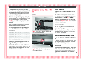
steering column. Fitting the front towing eye
Fig. 96
Front bumper on right: remove the lid. Fig. 97
Front bumper on right: towline an-
c hor
age screwed in. The housing of the screw towing eye is on the
right
s
ide of the front bumper behind a lid
››› Fig. 96.
The towing eye should always be kept in the
vehicle.
Bear in mind the instructions for towing
››› page 87.
Fitting the towline anchorage
● Remove the towing eye from the vehicle
too
l kit in the luggage compartment
››› page 83.
● Extract the lid for the towing eye using a
sc
rewdriver or similar and pressing on the
side.
● Remove the lid and let it hang from the ve-
hicl
e.
88
Page 91 of 328

Self-help
● Sc r
ew the towing eye in the housing by
turning it to the maximum anticlock-
wise ››› . Use a suitable object that can
c omp
letely and securely tighten the towing
eye in its housing.
● After towing, unscrew the towing eye cloc
k-
wise with a suitable object.
● Insert the side tab of the lid into the open-
ing of
the bumper and press until the tab is
properly clipped into the bumper.
● Clean the towing eye if necessary and then
st
ore it in the luggage compartment along
with the other vehicle tools. CAUTION
The towing eye must always be completely
and firm ly
tightened. Otherwise, it could be
released while towing and tow-starting. Fitting the rear towing eye
Fig. 98
Rear bumper on right: remove the lid. Fig. 99
Rear bumper on right: towline anchor-
ag e s
crewed in. The housing of the screw towing eye is on the
right
s
ide of the rear bumper behind a lid
››› Fig. 98. Vehicles equipped as standard
with a towing bracket do not have any hous-
ing for the screw towing eye behind the lid. In
this case, the tow hitch needs to be extracted or installed and used for towing
››
› page 255, ››› .
B e
ar in mind the instructions for towing
››› page 87.
Assemble the rear towing eye (cars without a
factory-equipped towing bracket)
● Remove the towing eye from the vehicle
too
l kit in the luggage compartment
››› page 83.
● Press the upper side of the lid ››
› Fig. 98 to
unclip it.
● Remove the lid and let it hang from the ve-
hicl
e.
● Screw the towing eye in the housing by
turnin
g it to the maximum anticlockwise
››› Fig. 99 ››› . Use a suitable object that can
c omp
letely and securely tighten the towing
eye in its housing.
● After towing, unscrew the towing eye cloc
k-
wise with a suitable object.
● Insert the upper flange of the lid into the
opening of
the bumper and press the lower
side of the lid until the upper flange is inser-
ted into the bumper.
● Clean the towing eye if necessary and then
st
ore it in the luggage compartment along
with the other vehicle tools. »
89
Technical data
Advice
Operation
Emergencies
Safety
Page 92 of 328

Emergencies
CAUTION
● The t o
wing eye must always be completely
and firmly tightened. Otherwise, it could be
released while towing and tow-starting.
● If the vehicle is factory-equipped with a
to
wing bracket, it is only allowed to tow with
a tow bar if this has been specially designed
to be installed with a tow hitch. If an unsuita-
ble tow bar is used, both the tow hitch and
the vehicle may be damaged. Instead, a tow
rope should be used. Driving tips for towing
Towing requires some expertise and experi-
enc
e, e
specially when using a tow rope. Both
drivers should be familiar with the difficulties
involved in towing. For this reason, inexper-
ienced drivers should abstain from towing.
During towing, it should be ensured that no
impermissible tractive forces or shocks are
generated. When towing on an unpaved
road, there is always a risk of overloading
and damaging the anchorage points.
During towing, the towing vehicle can signal
the change of direction even with the hazard
warning lights turned on. To do so, at the
same time, the turn signal lever must be op-
erated with ignition switched on. Meanwhile,
the hazard warning lights will go off. When
the turn signal lever is returned to the rest position, the hazard warning lights will be
autom
atically reactivated.
Notes for the driver of the towed vehicle ● Leave the ignition on, so that the steering
is
not blocked, and the electronic parking
brake may be deactivated and the turn sig-
nals and wash/wipe operated.
● More strength is required at the steering
wheel a
s the power steering does not oper-
ate when the engine is switched off.
● You should depress the brake much harder
as
the brake servo does not operate. Avoid
hitting the towing vehicle.
● Bear in mind the information and instruc-
tions
in the manual of the vehicle to be tow-
ed.
Notes for the driver of the towing vehicle
● Accelerate with particular care and caution.
Av
oid sharp manoeuvres.
● Brake earlier than usual and smoothly.
● Bear in mind the information and instruc-
tions
in the manual of the towed vehicle. Fuses and bulbs
F u
ses
Introduction In general, a fuse can be assigned to various
el
ectric
al components. Likewise, an electrical
component can be protected by several
fuses.
Only replace fuses when the cause of the
problem has been solved. If a newly inserted
fuse blows after a short time, you must have
the electrical system checked by a special-
ised workshop as soon as possible. WARNING
The high voltages in the electrical system can
giv e seriou
s electrical shocks, causing burns
and even death!
● Never touch the electrical wiring of the igni-
tion sys
tem.
● Take care not to cause short circuits in the
electric
al system. WARNING
Using unsuitable fuses, repairing fuses or
bridgin g a c
urrent circuit without fuses can
cause a fire and serious injury. 90
Page 93 of 328

Fuses and bulbs
●
Nev er u
se a fuse with a higher value. Only
replace fuses with a fuse of the same amper-
age (same colour and markings) and size.
● Never repair a fuse.
● Never replace a fuse by a metal strip, staple
or simi
lar. CAUTION
● To pr
event damage to the vehicle's electric
system, before replacing a fuse always turn
off the ignition, the lights and all electrical
elements and remove the key from the igni-
tion.
● If you replace a fuse with higher-rating
fu
se, you could cause damage to another part
of the electrical system.
● Protect the fuse boxes when open to pre-
vent
the entry of dust or humidity as they can
damage the electrical system. Note
● One c omponent
may have more than one
fuse.
● Several components may run on a single
fu
se. Vehicle fuses
Fig. 100
On the driver-side dash panel: fuse
bo x
cover Fig. 101
In the engine compartment: fuse box
c o
ver Read the additional information carefully
› ›
› page 51
Only replace fuses with a fuse of the same
amperage (same colour and markings) and
size. Opening and closing the fuse box situated
below the d
ash panel
● Opening: fold the cover down ›
›› Fig. 100.
● Closing: push back the cover it in until it
c
licks into place.
To open the engine compartment fuse box
● Open the bonnet ››
› page 282.
● Press the locking tabs to release the fuse
box
cover ››› Fig. 101.
● Then lift the cover out.
● To fit the cover, place it on the fuse box.
P
ush the locking tabs down until they click
audibly into place.
Fuses in the vehicle interior
No.Consumers/Amps
1Adblue (SCR)30
5Gateway5
6Automatic gearbox lever5
7Air conditioning and heating control
panel, back window heating, auxiliary
heating.10
8Diagnosis, handbrake switch, light
switch, reverse light, interior lighting,
driving mode10
9Steering column5
10Radio display7.5» 91
Technical data
Advice
Operation
Emergencies
Safety
Page 94 of 328

EmergenciesNo.Consumers/Amps
12Radio20
14Air conditioner fan40
15Steering column release10
16Connectivity box koppelantenne7.5
17Instrument panel5
18Rear camera7.5
19Kessy7.5
214x4 Haldex Control Unit15
22Trailer15
23Right lights40
24Electric sunroof30
25Left door30
26Heated seats30
28Trailer25
31Left lights40
32Parking aid control unit7.
5/10
33Airbag5
34Reverse switch, clima sensor, electro-
chromic mirror7.5
35Diagnosis, headlight control unit,
headlight adjuster10
No.Consumers/Amps
36Front camera, Radar5/10
38Trailer25
39Right door30
4012V socket20
42Central locking40
43Interior light30
44Trailer15
45Electric driver's seat15
47Rear window wiper15
49Starter motor; clutch sensor5
50Electric rear lid40
53Heated rear window30
Fuse arrangement in engine compartment
No.Consumers/Amps
1ESP control unit40
2ESP control unit40
3Engine control unit (diesel/pet-
rol)30/15
4Engine sensors5/10
5Engine sensors10
6Brake light sensor5
No.Consumers/Amps
7Engine power supply10
8Lambda probe10/15
9Engine5/20
10Fuel pump control unit15/20
11PTC40
12PTC40
13Automatic gearbox control unit15/30
14Heated windscreen40
15Horn15
17Engine control unit7.5
18Terminal 30 (positive reference)5
19Front windscreen washer30
20Alarm horn10
22Engine control unit5
23Starter motor30
24PTC40
31Pressure pump15
33Gearbox pump30
37Parking heating20 92
Page 95 of 328

Fuses and bulbs
CAUTION
● Alw
ays carefully remove the fuse box cov-
ers and refit them correctly to avoid problems
with your vehicle.
● Protect the fuse boxes when open to avoid
the entry
of dust or humidity. Dirt and humid-
ity inside fuse boxes can cause damage to
the electrical system. Note
● In the v
ehicle, there are more fuses than
those indicated in this chapter. These should
only be changed by a specialised workshop.
● Positions not containing a fuse do not ap-
pear in the f
ollowing tables.
● Some of the equipment listed in the tables
below per
tain only to certain versions of the
model or are optional extras.
● Please note that the above lists, while cor-
rect
at the time of printing, are subject to
change. Changing bulbs
Topic
introduction Read the additional information carefully
› ›
› page 52.
Changing bulbs requires a certain degree of
practical skill. If you choose to change the engine compart-
ment l
amps yourself, remember that it is a
dangerous area ››› in Work in the engine
c omp
artment on page 283.
Always use identical bulbs with the same
designation. The name can be found on the
base of the bulb holder.
Depending on how equipped the vehicle is,
there are different sets of headlights and tail
lights:
● Halogen headlights
● Full-LED main headlights*
● Rear bulb light
● LED rear light*
Fu
ll-LED headlight system*
Full-LED headlights handle all light functions
(daylight, side light, turn signal, dipped
beam and route light) with light emitting di-
odes (LEDs) as a light source.
Full-LED headlights are designed to last the
lifetime of the car and light bulbs cannot be
replaced. In case of headlight failure, go to
an authorised workshop to have it replaced. WARNING
● Tak
e particular care when working on com-
ponents in the engine compartment if the en-
gine is warm. Risk of burns. ●
Bu
lbs are highly sensitive to pressure. The
glass can break when you touch the bulb,
causing injury.
● When changing bulbs, please take care not
to injur
e yourself on sharp edges, in particu-
lar on the headlight housing. CAUTION
● Remo
ve the ignition key before working on
the electric system. Otherwise, a short circuit
could occur.
● Switch off the lights and the parking light
befor
e changing a bulb.
● Take good care to avoid damaging any com-
ponents. For the sake of the environment
Please ask your specialist retailer how to dis-
po se of
used bulbs in the proper manner. Note
● Ple
ase check at regular intervals that all
lighting (especially the exterior lighting) on
your vehicle is functioning properly. This is
not only in the interest of your own safety,
but also that of all other road users.
● Before changing a bulb, make sure you
hav
e the correct new bulb.
● Do not touch the glass part of the bulb with
your b
are hands, use a cloth or paper towel
instead, since the fingerprints left on the » 93
Technical data
Advice
Operation
Emergencies
Safety
Page 96 of 328
Emergencies
glass will vaporise as a result of the heat
g
ener
ated by the bulb, they will be deposited
on the reflector and will impair its surface. Change the front bulbs
Dip ped be
am headlightFig. 102
In the engine compartment: remove
the lid. Fig. 103
In the engine compartment: dipped
beam he
adlight. Follow the steps indicated:
Rai
se the bonnet.
Move the loops ›››
Fig. 102 1 in the di-
r ection of
the arrow and remove the cov-
er.
Remove connector ›››
Fig. 103 2 from
the b u
lb.
Unclip the retainer spring ›››
Fig. 103 3 pressing clockwise and inwards.
Extr
act
the bulb and fit the replacement
so that the lug on the base fits into the
recess on the reflector.
Installation involves all of the above
steps in reverse sequence.
1.
2.
3.
4.
5.
6. Main beam headlight bulb and turn
sign
al bulb Fig. 104
In the engine compartment: remove
the lid. 94