2017 PEUGEOT PARTNER TEPEE ELECTRIC ECU
[x] Cancel search: ECUPage 19 of 252
17
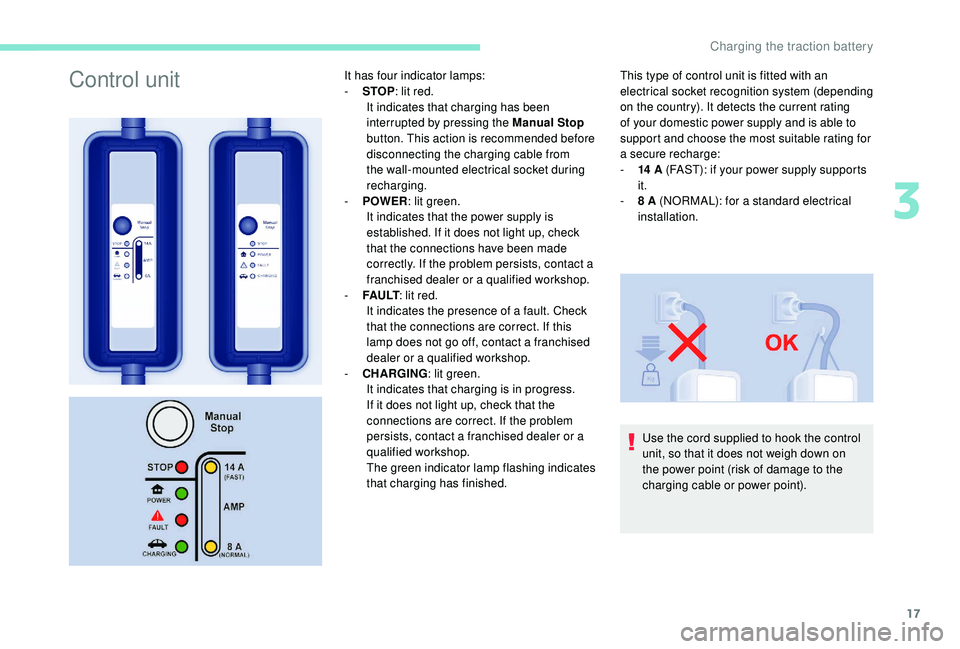
Control unitIt has four indicator lamps:
- S TOP: lit red.
It indicates that charging has been
interrupted by pressing the Manual Stop
button. This action is recommended before
disconnecting the charging cable from
the wall-mounted electrical socket during
recharging.
-
P
OWER : lit green.
It indicates that the power supply is
established. If it does not light up, check
that the connections have been made
correctly. If the problem persists, contact a
franchised dealer or a qualified workshop.
-
F
A U LT : lit red.
It indicates the presence of a fault. Check
that the connections are correct. If this
lamp does not go off, contact a franchised
dealer or a qualified workshop.
-
C
HARGING : lit green.
It indicates that charging is in progress.
If it does not light up, check that the
connections are correct. If the problem
persists, contact a franchised dealer or a
qualified workshop.
The green indicator lamp flashing indicates
that charging has finished. This type of control unit is fitted with an
electrical socket recognition system (depending
on the country). It detects the current rating
of your domestic power supply and is able to
support and choose the most suitable rating for
a secure recharge:
-
14
A (FAST): if your power supply supports
it.
-
8
A (NORMAL): for a standard electrical
installation.
Use the cord supplied to hook the control
unit, so that it does not weigh down on
the power point (risk of damage to the
charging cable or power point).
3
Charging the traction battery
Page 29 of 252
27
Ancillaries battery
All other electrical components on your vehicle
are powered by the ancillaries battery.
It is located in the front compartment under the
bonnet and is charged by the traction battery,
during the operation ("Ready" lamp in the
instrument panel) and charging phases.If the ancillaries battery is discharged,
the electric motor cannot be started and
charging of the traction battery is no
longer possible.
It is recommended that the ancillaries
battery be disconnected if the vehicle is
not to be used for more than a month.
Access to the battery Starting using an external battery
Ensure that the backup battery is a 12 volt
b attery.
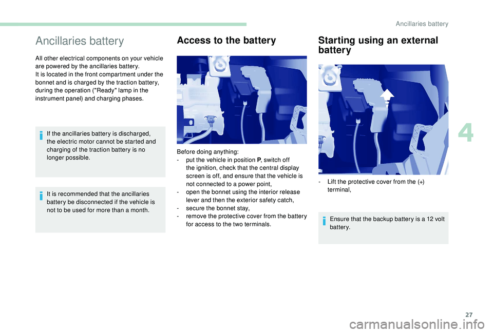
Before doing anything:
-
p
ut the vehicle in position P
, switch off
the ignition, check that the central display
screen is off, and ensure that the vehicle is
not connected to a power point,
-
o
pen the bonnet using the interior release
lever and then the exterior safety catch,
-
s
ecure the bonnet stay,
-
r
emove the protective cover from the battery
for access to the two terminals. -
L
ift the protective cover from the (+)
terminal,
4
Ancillaries battery
Page 40 of 252

2
.
.
Instrument panel 7
W arning and indicator lamps 8
I
ndic ators
18
Lighting dimmer
2
2
Trip computer
2
2
Date and time setting
2
3
Instruments and controls
4
K
ey
25
Remote control
2
5
Front doors
2
8
Sliding side door(s)
2
8
Operation in the event of a battery failure
2
9
Tailgate
29
Side-hinged rear doors
3
0
Rear roof flap
3
2
Central locking
3
3
Alarm
34
Rear windows
3
5
Electric windows
3
5Steering wheel adjustment
3
7
Mirrors
37
Surveillance mirror
3
8
Front seats
3
8
Individual passenger seat
4
0
Multi-Flex bench seat
4
0
Rear bench seat
4
2
Rear seats (5 seats) 4 3
Rear seats (7 seats) 4 6
Crew cab
5
0
Seat modularity and configurations
5
2
Front fittings
5
4
Seating area fittings
5
5
Zenith
56
Fragrance diffuser
5
7
Courtesy lamps
5
9
Rear fittings (5 seats)
6
0
Rear fittings (7 seats)
6
1
Load space layout
6
4
Heating/Manual air conditioning
6
6
Dual-zone automatic air conditioning
6
7
Recommendations for ventilation
and air conditioning
6
9
Demisting and defrosting
7
0Lighting control stalk
7
1
Automatic illumination of headlamps
7
2
LED daytime running lamps
7
2
Guide-me-home lighting
7
2
Cornering lighting
7
3
Direction indicators
7
3
Headlamp beam
7
3
Wiper control stalk 7 3
General safety recommendations
7
6
Hazard warning lamps
7
7
Horn
77
Emergency or assistance call
7
7
Anti-lock braking system (ABS/EBFD)
7
9
Emergency braking assistance (EBA)
7
9
Anti-slip regulation (ASR) and electronic
stability control (ESC)
7
9
Grip control
8
0
Seat belts
8
2
Airbags
85
Child seats
8
9
Deactivating the passenger's front airbag
9
0
Reactivating the passenger's front airbag
9
1
Recommended child seats
9
4
Locations for child seats secured using
a seat belt
9
5
ISOFIX mountings and child seats
9
8
Instructions for child seats
1
01
Child lock
1
02
Over view
Instruments
Access Ease of use and comfort
Safety
Lighting and visibility
Eco-driving
Contents
Page 63 of 252
25
Key
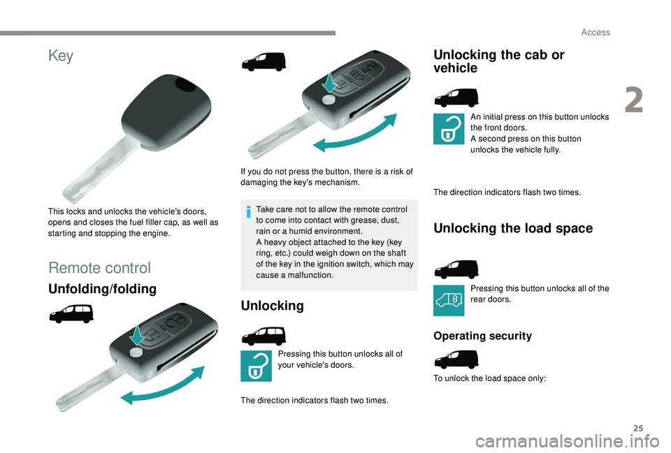
This locks and unlocks the vehicle's doors,
opens and closes the fuel filler cap, as well as
starting and stopping the engine.
Remote control
Unfolding/folding
If you do not press the button, there is a risk of
damaging the key's mechanism.Take care not to allow the remote control
to come into contact with grease, dust,
rain or a humid environment.
A heavy object attached to the key (key
ring, etc.) could weigh down on the shaft
of the key in the ignition switch, which may
cause a malfunction.
Unlocking
Pressing this button unlocks all of
your vehicle's doors.
The direction indicators flash two times.
Unlocking the cab or
vehicle
An initial press on this button unlocks
the front doors.
A second press on this button
unlocks the vehicle fully.
The direction indicators flash two times.
Unlocking the load space
Pressing this button unlocks all of the
rear doors.
Operating security
To unlock the load space only:
2
Access
Page 70 of 252
32
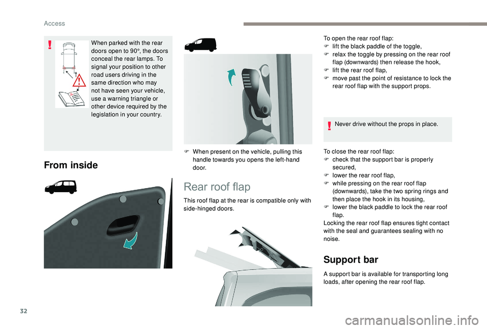
When parked with the rear
doors open to 90°, the doors
conceal the rear lamps. To
signal your position to other
road users driving in the
same direction who may
not have seen your vehicle,
use a warning triangle or
other device required by the
legislation in your country.
From inside
F When present on the vehicle, pulling this handle towards you opens the left-hand
d o o r.
Rear roof flap
This roof flap at the rear is compatible only with
side-hinged doors. To open the rear roof flap:
F
l
ift the black paddle of the toggle,
F
r
elax the toggle by pressing on the rear roof
flap (downwards) then release the hook,
F
l
ift the rear roof flap,
F
m
ove past the point of resistance to lock the
rear roof flap with the support props.
Never drive without the props in place.
To close the rear roof flap:
F
c
heck that the support bar is properly
secured,
F
l
ower the rear roof flap,
F
w
hile pressing on the rear roof flap
(downwards), take the two spring rings and
then place the hook in its housing,
F l ower the black paddle to lock the rear roof
flap.
Locking the rear roof flap ensures tight contact
with the seal and guarantees sealing with no
noise.
Support bar
A support bar is available for transporting long
loads, after opening the rear roof flap.
Access
Page 71 of 252
33
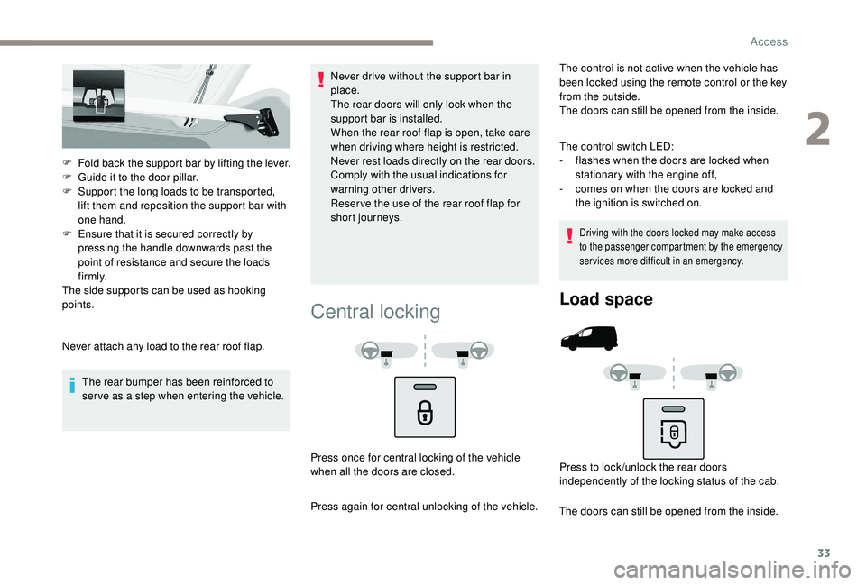
F Fold back the support bar by lifting the lever.
F G uide it to the door pillar.
F
S
upport the long loads to be transported,
lift them and reposition the support bar with
one hand.
F
E
nsure that it is secured correctly by
pressing the handle downwards past the
point of resistance and secure the loads
f i r m l y.
The side supports can be used as hooking
points.
Never attach any load to the rear roof flap.
The rear bumper has been reinforced to
serve as a step when entering the vehicle. Never drive without the support bar in
place.
The rear doors will only lock when the
support bar is installed.
When the rear roof flap is open, take care
when driving where height is restricted.
Never rest loads directly on the rear doors.
Comply with the usual indications for
warning other drivers.
Reser ve the use of the rear roof flap for
short journeys.
Central locking
The control is not active when the vehicle has
been locked using the remote control or the key
from the outside.
The doors can still be opened from the inside.
The control switch LED:
-
f
lashes when the doors are locked when
stationary with the engine off,
-
c
omes on when the doors are locked and
the ignition is switched on.
Driving with the doors locked may make access
to the passenger compartment by the emergency
services more difficult in an emergency.
Press once for central locking of the vehicle
when all the doors are closed.
Press again for central unlocking of the vehicle.
Load space
Press to lock /unlock the rear doors
independently of the locking status of the cab.
The doors can still be opened from the inside.
2
Access
Page 74 of 252
36
The electrical functions of the electric windows
are deactivated:
-
a
pproximately 45 seconds after the ignition
is switched off,
-
a
fter one of the front doors is opened, if the
ignition is off.
Safety anti-pinch
When the window rises and meets an obstacle,
it stops and partially lowers again.
Reinitialisation
Following reconnection of the battery, or in the
event of a malfunction, the anti-pinch function
must be reinitialised.
F
B
ring the window down completely, then
bring it back up. It will go up by a few
centimetres with each press. Repeat the
operation until the window is fully closed.
F
H
old the switch pressed for at least one
second after reaching the window closed
position.
The safety anti-pinch does not operate during
these operations. In the event of contact (pinching) during
operation of the windows, you must
reverse the movement of the window. To
do this, press the switch concerned.
When operating the passenger electric
window switches, the driver must ensure
that no one is preventing correct closing of
the windows.
The driver must ensure that the
passengers use the electric windows
c o r r e c t l y.
Be aware of children when operating the
windows.
After several consecutive attempts to
close/open the windows using the electric
windows control, a protection system
engages, which only allows for the
windows to be closed. After closing, wait
approximately 40
minutes. After this time,
the control will be operational again.
Access
Page 79 of 252
41
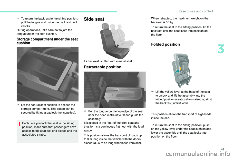
F To return the backrest to the sitting position, pull the tongue and guide the backrest until
it locks.
During operations, take care not to jam the
tongue under the seat cushion.
Storage compartment under the seat
cushion
Each time you lock the seat in the sitting
position, make sure that passengers have
access to the seat belt end pieces and the
associated straps.
Side seat
Retractable position
When retracted, the maximum weight on the
backrest is 50 kg.
To return the seat to the sitting position, lift the
backrest until the seat locks into position on
t h e f l o o r.
F
L
ift the central seat cushion to access the
storage compartment. This space can be
secured by fitting a padlock (not supplied). Its backrest is fitted with a metal shell.
F
P
ull the tongue on the top edge of the seat
near the head restraint to tilt and guide the
assembly.
It is placed in the floor of the front seat and
thus forms a continuous flat floor with the load
space.
This position allows the transport of loads up
to 3
m long inside the vehicle with the doors
closed (3.25
m on long wheelbase versions).
Folded position
This position allows the transport of high loads
inside the cab.
To return the seat to the sitting position, push
on the yellow lever under the seat cushion and
lower the assembly until the seat locks into
position on the floor. F
L
ift the yellow lever at the base of the seat
to unlock and lift the assembly into the
folded position (seat cushion raised against
the backrest) until it locks.
3
Ease of use and comfort