2017 PEUGEOT PARTNER TEPEE ELECTRIC ECU
[x] Cancel search: ECUPage 136 of 252
98
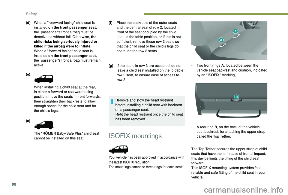
ISOFIX mountings
Your vehicle has been approved in accordance with
the latest ISOFIX regulation.
The mountings comprise three rings for each seat:
- Two front rings A, located between the
vehicle seat backrest and cushion, indicated
by an "ISOFIX" marking,
-
A r
ear ring B , on the back of the vehicle
seat backrest, for attaching the upper strap
called the Top Tether.
The Top Tether secures the upper strap of child
seats that have them. In case of frontal impact,
this device limits the tilting of the child seat
forward.
This ISOFIX mounting system provides fast,
reliable and safe fitting of the child seat in your
vehicle.
Remove and stow the head restraint
before installing a child seat with backrest
on a passenger seat.
Refit the head restraint once the child seat
has been removed.
(d)
When a "rear ward facing" child seat is
installed on the front passenger seat ,
the passenger's front airbag must be
deactivated without fail. Otherwise, the
child risks being seriously injured or
killed if the airbag were to inflate .
When a "for ward facing" child seat is
installed on the front passenger seat ,
the passenger's front airbag must remain
active.
(e)
When installing a child seat at the rear,
in either a for ward or rear ward facing
position, move the seats in front for wards,
then straighten their backrests to allow
enough space for the child seat and for
the child's legs.
(e)
The "RÖMER Baby-Safe Plus" child seat
cannot be installed on this seat. (f )
Place the backrests of the outer seats
and the central seat of row 2, located in
front of the seat occupied by the child
seat, in the table position, or if this is not
sufficient, remove these row 2 seats so
that the child seat or the child's legs do
not touch the row 2 seats.
(g) If the seats in row 3 are occupied, do not
leave a child seat installed on the foldable
row 2 seat, to ensure ease of access to
row 3.
Safety
Page 137 of 252
99
The ISOFIX child seats are fitted with two
latches which are secured on the two front
rings A.
Some also have an upper strap which is
attached to rear ring B .
To secure the child seat to the Top Tether:
-
r
emove and stow the head restraint before
installing a child seat on this seat (refit it
once the child seat has been removed),
-
r
un the strap of the child seat behind the top
of the seat backrest, centring it between the
holes for the head restraint rods,
-
f
ix the hook of the upper strap to rear ring B ,
-
t
ighten the upper strap.The incorrect installation of a child seat in
a vehicle compromises the protection of
the child in the event of an accident.
Strictly follow the fitting instructions
provided in the installation guide supplied
with the child seat.
For information on the possibilities for
installing ISOFIX child seats in your
vehicle, refer to the locations table.Recommended ISOFIX seat Locations of ISOFIX child seats
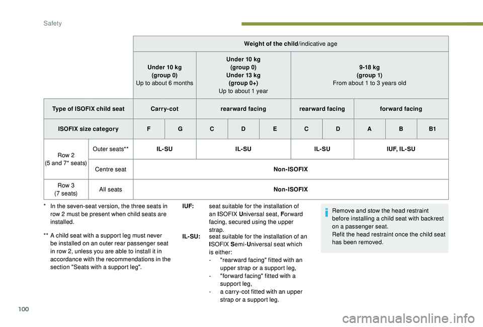
In line with European regulations, this table
indicates the options for installing ISOFIX child
seats on the vehicle seats fitted with ISOFIX
mountings.
In the case of the universal and semi-universal
ISOFIX child seats, the child seat's ISOFIX size
category, designated by a letter from A to G , is
indicated on the child seat next to the ISOFIX
logo.
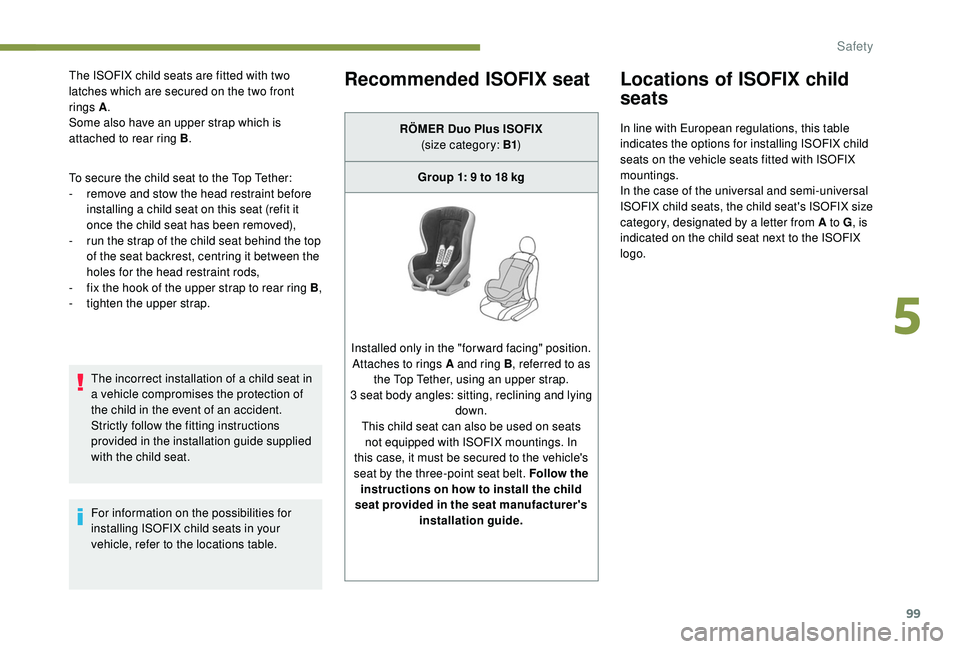
RÖMER Duo Plus ISOFIX
(size category: B1 )
Group 1: 9 to 18
kg
Installed only in the "forward facing" position. Attaches to rings A and ring B , referred to as
the Top Tether, using an upper strap.
3 seat body angles: sitting, reclining and lying down.
This child seat can also be used on seats not equipped with ISOFIX mountings. In
this case, it must be secured to the vehicle's
seat by the three-point seat belt. Follow the instructions on how to install the child
seat provided in the seat manufacturer's installation guide.
5
Safety
Page 138 of 252
100
Remove and stow the head restraint
before installing a child seat with backrest
on a passenger seat.
Refit the head restraint once the child seat
has been removed.
Weight of the child
/indicative age
Under 10
kg
(group 0)
Up to about 6
months
Under 10
kg
(group 0)
Under 13
kg
(group 0+)
Up to about 1 year 9 -18
kg
(g ro up 1)
From about 1 to 3 years old
Type of ISOFIX child seat Carr y- cotrearward facing rearward facing forward facing
ISOFIX size categor y F G C D E C D A B B1
Row 2
(5 and 7* seats) Outer seats**
IL- SU IL- SUIL- SUI U F, I L - S U
Centre seat Non-ISOFIX
Row 3
(7 seats) All seats
Non-ISOFIX
*
I
n the seven-seat version, the three seats in
row 2
must be present when child seats are
installed.
**
A c
hild seat with a support leg must never
be installed on an outer rear passenger seat
in row 2, unless you are able to install it in
accordance with the recommendations in the
section "Seats with a support leg". I UF:
seat suitable for the installation of
an ISOFIX U niversal seat, F or ward
facing, secured using the upper
strap.
IL- SU: seat suitable for the installation of an
ISOFIX S emi-Universal seat which
is either:
-
"
rear ward facing" fitted with an
upper strap or a support leg,
-
"
for ward facing" fitted with a
support leg,
-
a c
arry-cot fitted with an upper
strap or a support leg.
Safety
Page 139 of 252
101
Instructions for child seats
The incorrect installation of a child seat in a
vehicle compromises the child's protection in
the event of an accident.
Ensure that there is no seat belt or seat belt
buckle under the child seat, as this could
destabilise it.
Remember to fasten the seat belts or the
child seat harnesses keeping the slack
relative to the child's body to a minimum,
even for short journeys.
When installing a child seat using the seat
belt, ensure that the seat belt is tightened
correctly on the child seat and that it secures
the child seat firmly on the seat of your
vehicle. If your passenger seat is adjustable,
move it for wards if necessary.
At the rear, always leave sufficient space
between the front seat and:
-
a r
ear ward facing child seat,
-
t
he feet of a child seated in a for ward
facing child seat.
To do this, move the front seat for wards
and, if necessary, move its backrest into the
upright position. When a child seat is installed in row 3, place
the backrests of the outer seats and the
centre seat of row 2 in the table position, or
remove these row 2 seats so that the child
seat or the child's legs do not touch the row
2 seats.
For optimal installation of the "forward facing"
child seat, check that its backrest is as close
as possible to the backrest of the vehicle
seat, if possible in contact with it.
The head restraint must be removed before
installing a child seat with a backrest on a
passenger seat.
Ensure that the head restraint is stored or
attached securely to prevent it from being
thrown around the vehicle in the event of
sharp braking.
Refit the head restraint once the child seat
has been removed.
Installing a booster (height adjuster)
The chest part of the seat belt must be
positioned on the child's shoulder without
touching the neck.
Ensure that the lap part of the seat belt
passes correctly over the child's thighs.
PEUGEOT recommends using a booster seat
with a backrest, equipped with a belt guide at
shoulder level.
As a safety precaution, do not leave:
-
a c
hild or children alone and unattended in
a vehicle,
-
a c
hild or an animal in a vehicle which
is exposed to the sun, with the windows
closed,
-
t
he keys within reach of children inside the
vehicle.
To prevent accidental opening of the doors,
use the "Child lock" system.
Take care not to open the rear windows by
more than one third.
To protect young children from the rays of the
sun, fit side blinds on the rear windows.
Children in front
The legislation on carrying children on the
front passenger seat is specific to each
country. Refer to the legislation in force in
your country.
Deactivate the passenger’s front airbag when
a rear ward facing child seat is installed on
the front passenger seat. Otherwise, the child
may be seriously injured or killed if the airbag
is deployed.
5
Safety
Page 143 of 252

105
Electronic engine
immobiliser
All of the keys contain an electronic immobiliser
device.
This device locks the engine supply system.
It is activated automatically when the key is
removed from the ignition.
When the ignition switch is turned on, a
dialogue is set up between the key and the
electronic immobiliser.
The metal part of the key must be correctly
unfolded to ensure a good connection.
In case of lost keys
See a PEUGEOT dealer with the vehicle
registration certificate and your ID.
A PEUGEOT dealer can retrieve the key
code and the transponder code to order the
replacement key.
When you leave the vehicle, check that the
lamps are off and do not leave valuables
visible.
As a safety precaution (with children on
board), remove the key from the ignition when
leaving the vehicle, even for a short time.
Parking brake
Application
F Pull the parking brake lever up to immobilise your vehicle.
F
C
heck that the parking brake is applied
firmly before leaving the vehicle.
When parking on a slope, turn your
wheels towards the kerb and pull the
parking brake lever up.
There is no advantage in engaging a gear
after parking the vehicle, particularly if the
vehicle is loaded. Apply the parking brake only when the
vehicle is stationary
.
In the exceptional case of use of the
parking brake when the vehicle is moving,
apply the brake by pulling gently to avoid
locking the rear wheels (risk of skidding).
Release
F Pull the lever up slightly and press the button to release the parking brake lever.
When the vehicle is being driven, this
warning lamp coming on indicates
that the parking brake is still on or
has not been fully released.
Manual gearbox
To change gear easily, always press the clutch
pedal fully.
To prevent the mat from becoming caught
under the pedal:
-
e
nsure that the mat is positioned and
secured to the floor correctly,
-
n
ever fit one mat on top of another.
When driving, avoid leaving your hand on the
gear knob as the force exerted, even if slight,
may wear the internal components of the
gearbox over time.
6
Driving
Page 155 of 252
117
Pressing the accelerator pedal in order to
exceed the programmed speed will have
no effect unless you press the pedal firmly
beyond the point of resistance .
The speed limiter is deactivated temporarily
and the programmed speed setting flashes,
accompanied by an audible signal.
To return to the limiter function, reduce your
speed below the programmed speed.
Flashing of the speed setting
It flashes:
- a fter forcing the accelerator pedal past the
point of resistance,
-
w
hen the limiter cannot prevent the speed
of the vehicle increasing, because of the
profile of the road or when going down a
steep hill,
-
u
nder sharp acceleration.
Switching the funtion off
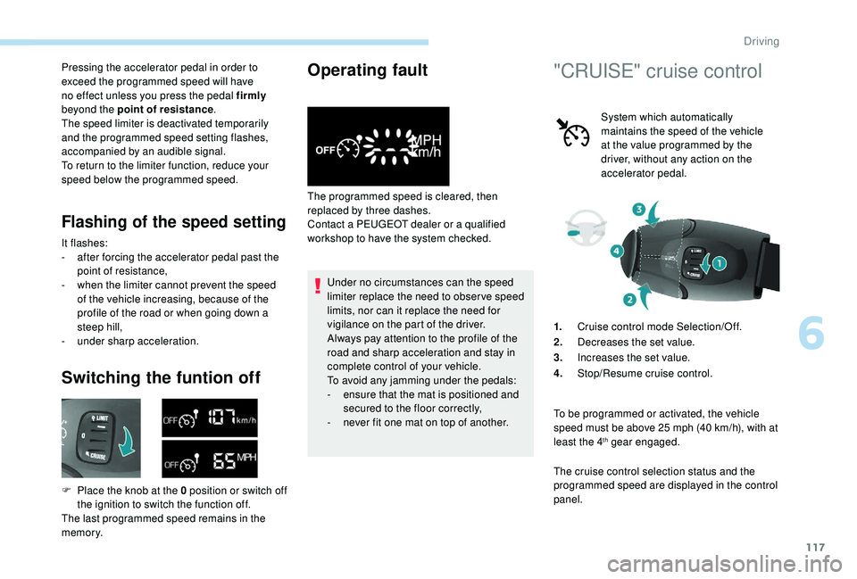
F Place the knob at the 0 position or switch off the ignition to switch the function off.
The last programmed speed remains in the
memory.
Operating fault
The programmed speed is cleared, then
replaced by three dashes.
Contact a PEUGEOT dealer or a qualified
workshop to have the system checked.
Under no circumstances can the speed
limiter replace the need to obser ve speed
limits, nor can it replace the need for
vigilance on the part of the driver.
Always pay attention to the profile of the
road and sharp acceleration and stay in
complete control of your vehicle.
To avoid any jamming under the pedals:
-
e
nsure that the mat is positioned and
secured to the floor correctly,
-
n
ever fit one mat on top of another.
"CRUISE" cruise control
System which automatically
maintains the speed of the vehicle
at the value programmed by the
driver, without any action on the
accelerator pedal.
1. Cruise control mode Selection/Off.
2. Decreases the set value.
3. Increases the set value.
4. Stop/Resume cruise control.
To be programmed or activated, the vehicle
speed must be above 25
mph (40 km/h), with at
least the 4
th gear engaged.
The cruise control selection status and the
programmed speed are displayed in the control
panel.
6
Driving
Page 158 of 252
120
When changing the programmed
reference speed by means of a maintained
press, remain vigilant as the speed can
increase or decrease rapidly.
Do not use the cruise control on slippery
roads or in heavy traffic.
When descending a steep hill, the cruise
control system cannot prevent the vehicle
from exceeding the programmed speed.
The cruise control system cannot in
any circumstances replace the need
to obser ve speed limits or the need for
vigilance on the part of the driver.
It is advisable to leave your feet near the
pedals.
To avoid any jamming under the pedals:
-
e
nsure that the mat is positioned and
secured to the floor correctly,
-
n
ever fit one mat on top of another.
Active City Brake
Active City Brake is a driving assistance
system that aims to avoid a frontal collision
or reduce the speed of an impact if the driver
does not react sufficiently (inadequate brake
application). This system has been designed to
improve driving safety.
The driver must always check the traffic
and assess the distance and relative
speed of other vehicles.
Active City Brake cannot in any
circumstances replace the need for
vigilance on the part of the driver.
Never look at the laser sensor through
an optical instrument (magnifying glass,
microscope, etc.) at a distance of less
than 10
centimetres: risk of eye injury!
Principle
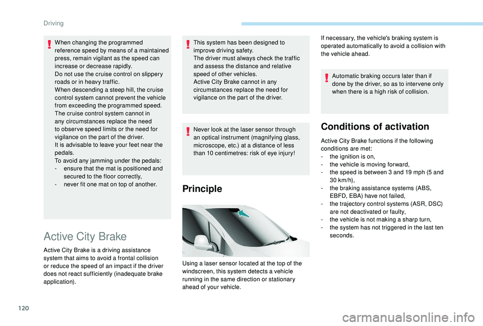
Using a laser sensor located at the top of the
windscreen, this system detects a vehicle
running in the same direction or stationary
ahead of your vehicle.Automatic braking occurs later than if
done by the driver, so as to inter vene only
when there is a high risk of collision.
Conditions of activation
Active City Brake functions if the following
conditions are met:
-
t
he ignition is on,
-
t
he vehicle is moving for ward,
-
t
he speed is between 3 and 19 mph (5 and
30
km/h),
-
t
he braking assistance systems (ABS,
EBFD, EBA) have not failed,
-
t
he trajectory control systems (ASR, DSC)
are not deactivated or faulty,
-
t
he vehicle is not making a sharp turn,
-
t
he system has not triggered in the last ten
seconds.
If necessary, the vehicle's braking system is
operated automatically to avoid a collision with
the vehicle ahead.
Driving
Page 172 of 252
134
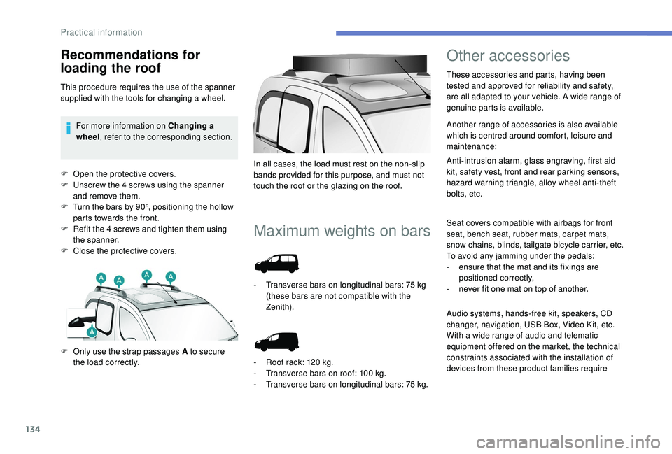
F Open the protective covers.
F U nscrew the 4 screws using the spanner
and remove them.
F
T
urn the bars by 90°, positioning the hollow
parts towards the front.
F
R
efit the 4 screws and tighten them using
the spanner.
F
C
lose the protective covers.
Maximum weights on bars
F Only use the strap passages A to secure the load correctly. In all cases, the load must rest on the non-slip
bands provided for this purpose, and must not
touch the roof or the glazing on the roof.
-
T
ransverse bars on longitudinal bars: 75 kg
(these bars are not compatible with the
Zenith).
-
R
oof rack: 120 kg.
-
T
ransverse bars on roof: 100 kg.
-
T
ransverse bars on longitudinal bars: 75
kg.
Other accessories
These accessories and parts, having been
tested and approved for reliability and safety,
are all adapted to your vehicle. A wide range of
genuine parts is available.
Another range of accessories is also available
which is centred around comfort, leisure and
maintenance:
Anti-intrusion alarm, glass engraving, first aid
kit, safety vest, front and rear parking sensors,
hazard warning triangle, alloy wheel anti-theft
bolts, etc.
Seat covers compatible with airbags for front
seat, bench seat, rubber mats, carpet mats,
snow chains, blinds, tailgate bicycle carrier, etc.
To avoid any jamming under the pedals:
-
e
nsure that the mat and its fixings are
positioned correctly,
-
n
ever fit one mat on top of another.
Recommendations for
loading the roof
This procedure requires the use of the spanner
supplied with the tools for changing a wheel.For more information on Changing a
wheel , refer to the corresponding section.
Audio systems, hands-free kit, speakers, CD
changer, navigation, USB Box, Video Kit, etc.
With a wide range of audio and telematic
equipment offered on the market, the technical
constraints associated with the installation of
devices from these product families require
Practical information