2017 PEUGEOT PARTNER TEPEE ELECTRIC warning
[x] Cancel search: warningPage 3 of 252
1
.
Instrument panel 3
I ndicators 3
Warning and indicator lamps
6
D
isplays
7
Starting procedure
8
E
co-driving
10
Eco-comfort
11
Manual air conditioning and heating
1
2Charging the traction battery
1
4
Normal charging procedure
2
0
Fast charging procedure
2
2
Other information
2
4
Ancillaries battery 2 7
Fuses
30
Towing the vehicle
3
0
Motor and traction battery
3
1
Identification markings
3
2
Presentation
Instruments and controls
Eco-comfort Charging the traction battery
Supplement for electric mode Ancillaries batteryThis supplement is specific to the electric
drive mode. For any other information, refer
to the vehicle's handbook and the warranty
and maintenance guide. You can also visit
the manufacturer's website for the latest
information.
The driver must be par ticularly vigilant
when driving the electric vehicle as it
makes ver y little noise when moving.
Key
Safety warning
Additional information
Warning of safety issues for people
and equipment.
For any work on your vehicle, go to a qualified
workshop that has the technical information,
competence and equipment required, which
the Manufacturer's dealer network is able to
provide.
Contents
.
Contents
Page 5 of 252
3
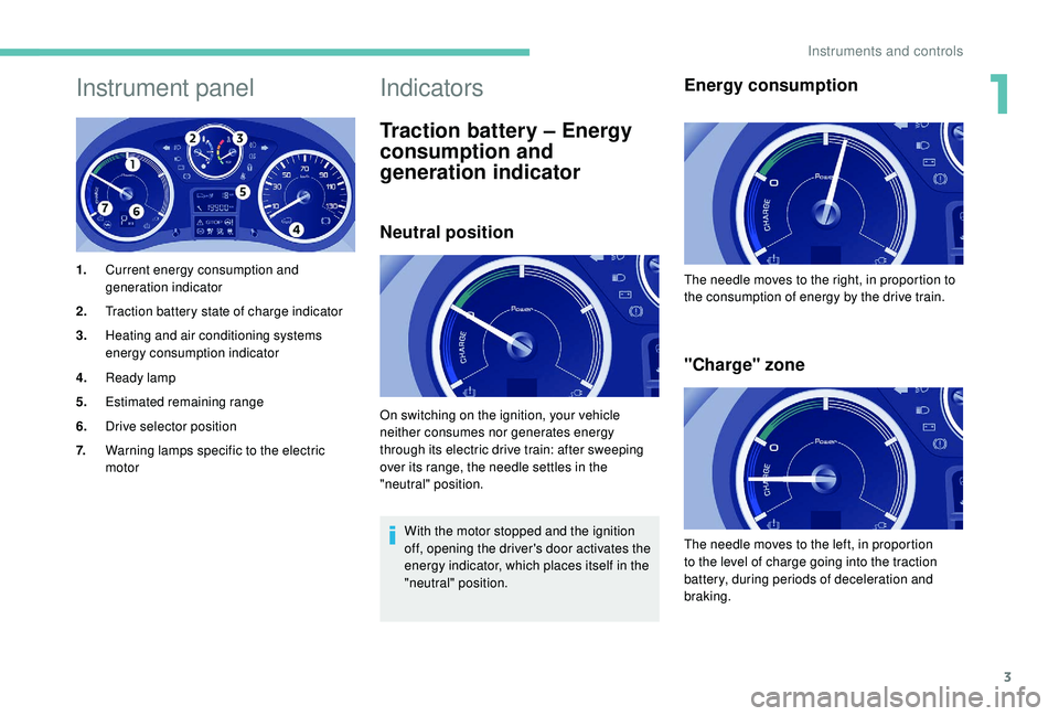
Instrument panel
1.Current energy consumption and
generation indicator
2. Traction battery state of charge indicator
3. Heating and air conditioning systems
energy consumption indicator
4. Ready lamp
5. Estimated remaining range
6. Drive selector position
7. Warning lamps specific to the electric
motor
Indicators
Traction battery – Energy
consumption and
generation indicator
Neutral position
With the motor stopped and the ignition
off, opening the driver's door activates the
energy indicator, which places itself in the
"neutral" position.
Energy consumption
"Charge" zone
On switching on the ignition, your vehicle
neither consumes nor generates energy
through its electric drive train: after sweeping
over its range, the needle settles in the
"neutral" position. The needle moves to the right, in proportion to
the consumption of energy by the drive train.
The needle moves to the left, in proportion
to the level of charge going into the traction
battery, during periods of deceleration and
braking.
1
Instruments and controls
Page 6 of 252
4
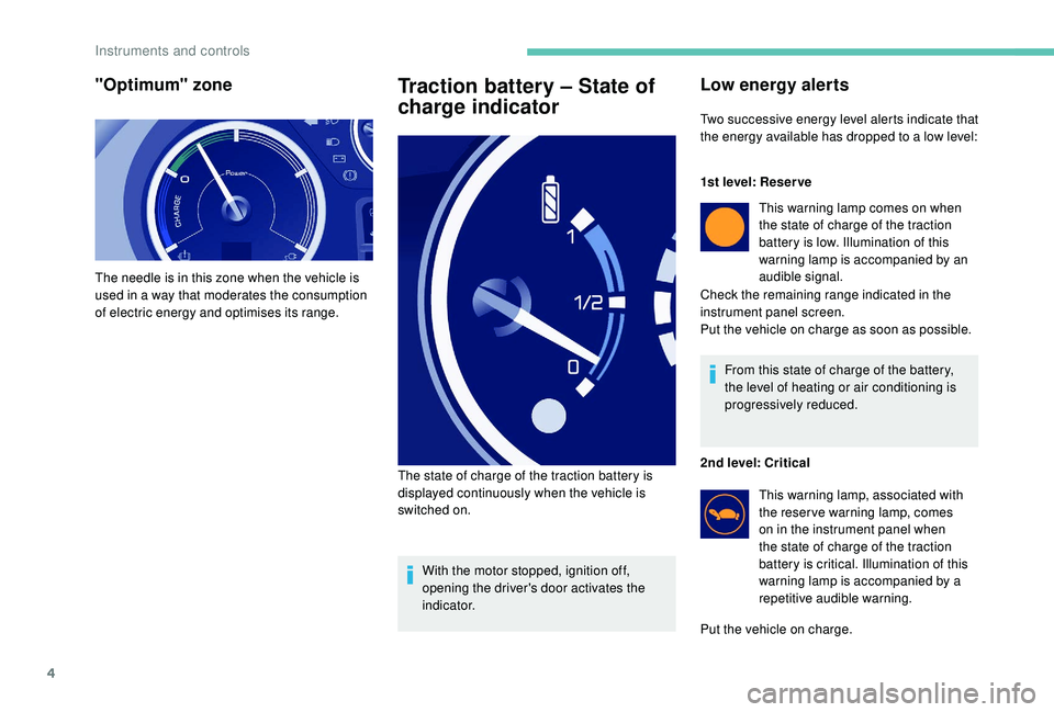
"Optimum" zone
The needle is in this zone when the vehicle is
used in a way that moderates the consumption
of electric energy and optimises its range.
Traction battery – State of
charge indicator
With the motor stopped, ignition off,
opening the driver's door activates the
i n d i c a t o r.
The state of charge of the traction battery is
displayed continuously when the vehicle is
switched on.
Low energy alerts
Two successive energy level alerts indicate that
the energy available has dropped to a low level:
1st level: Reser ve
This warning lamp comes on when
the state of charge of the traction
battery is low. Illumination of this
warning lamp is accompanied by an
audible signal.
Check the remaining range indicated in the
instrument panel screen.
Put the vehicle on charge as soon as possible.
From this state of charge of the battery,
the level of heating or air conditioning is
progressively reduced.
2nd level: Critical This warning lamp, associated with
the reser ve warning lamp, comes
on in the instrument panel when
the state of charge of the traction
battery is critical. Illumination of this
warning lamp is accompanied by a
repetitive audible warning.
Put the vehicle on charge.
Instruments and controls
Page 8 of 252
6
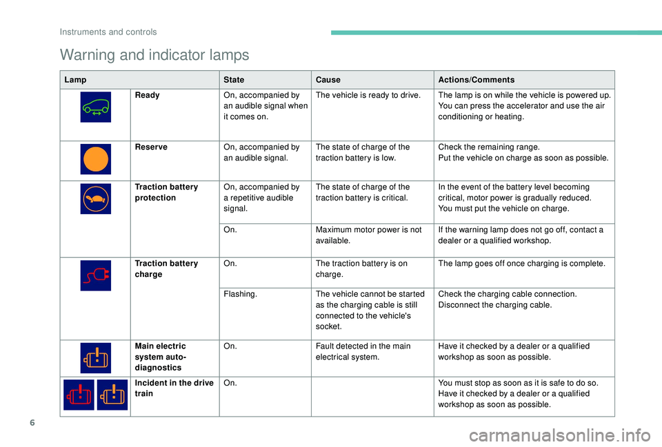
Warning and indicator lamps
LampStateCause Actions/Comments
Ready On, accompanied by
an audible signal when
it comes on. The vehicle is ready to drive. The lamp is on while the vehicle is powered up.
You can press the accelerator and use the air
conditioning or heating.
Reser ve On, accompanied by
an audible signal. The state of charge of the
traction battery is low. Check the remaining range.
Put the vehicle on charge as soon as possible.
Traction battery
protection On, accompanied by
a repetitive audible
signal. The state of charge of the
traction battery is critical.
In the event of the battery level becoming
critical, motor power is gradually reduced.
You must put the vehicle on charge.
On. Maximum motor power is not
available. If the warning lamp does not go off, contact a
dealer or a qualified workshop.
Traction battery
charge On.
The traction battery is on
charge. The lamp goes off once charging is complete.
Flashing. The vehicle cannot be started
as the charging cable is still
connected to the vehicle's
socket. Check the charging cable connection.
Disconnect the charging cable.
Main electric
system auto-
diagnostics On.
Fault detected in the main
electrical system. Have it checked by a dealer or a qualified
workshop as soon as possible.
Incident in the drive
train On.
You must stop as soon as it is safe to do so.
Have it checked by a dealer or a qualified
workshop as soon as possible.
Instruments and controls
Page 26 of 252
24
Other information
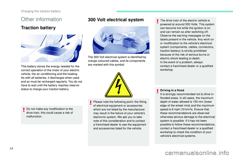
Traction battery
Do not make any modification to the
drive train, this could cause a risk of
malfunction.
300 Volt electrical system
The 300 Volt electrical system is identified by
o range coloured cables, and its components
are marked with this symbol:
Please note the following point: the fitting
of electrical equipment or accessories
which are not listed by the manufacturer
may result in the failure of your vehicle's
electronic system. We ask you to take
note of this consideration and to contact
a franchised dealer to see the equipment
and accessories listed for the vehicle. The drive train of the electric vehicle is
powered at around 300
Volts. This system
can become hot while the ignition is on
and can remain so after switching off.
Obser ve the warning messages on the
labels present in the vehicle. Any work on
or modification to the vehicle's electrical
system (components, cables, connectors,
traction battery) is strictly prohibited
because of the risk of serious burns or
electric shock leading to death.
In the event of a problem, always
contact a franchised dealer or a qualified
workshop.
Driving in a flood
It is strongly recommended not to drive in
flooded areas. In all cases, the maximum
depth of water allowed is 150
mm (lower
edge of the wheel rims) and the maximum
speed is 6
mph (10 km/h). Ensure that
these recommendations are observed
otherwise serious damage to the electrical
system is possible. If it has not been
possible to follow these recommendations,
contact a franchised dealer or a qualified
workshop to check the condition of your
vehicle's electrical systems.
This battery stores the energy needed for the
correct operation of the motor of your electric
vehicle, the air conditioning and the heating.
As with all batteries, it discharges when used
and so must be recharged regularly. You do not
have to wait until the battery reaches reser ve
status to charge your traction battery.
Charging the traction battery
Page 39 of 252
Welcome
Thank you for choosing a Peugeot Partner.
This document presents the information and recommendations required
for you to be able to explore your vehicle in complete safety.
Your vehicle will be fitted with only some of the equipment described in
this document, depending on its trim level, version and the specification
for the country in which it was sold.
The descriptions and illustrations are given as indications only.
Automobiles PEUGEOT reser ves the right to modify the technical
specifications, equipment and accessories without having to update this
edition of the handbook.
If ownership of your vehicle is transferred, please ensure this Complete
Handbook is passed on to the new owner.
In this document you will find all of the instructions and
recommendations on use that will allow you to enjoy your vehicle to the
fullest. It is strongly recommended that you familiarise yourself with it
as well as the Warranty and Maintenance Record which will provide
you with information about the warranties, ser vicing and roadside
assistance associated with your vehicle. Key
Safety warning
Additional information
Contributes to the protection of the
environment
Left-hand drive vehicle
Right-hand drive vehicle
Key
This allows you to identify the special features of your vehicle: Partner Tepee passenger vehicle only
Partner commercial vehicle only
Page 40 of 252

2
.
.
Instrument panel 7
W arning and indicator lamps 8
I
ndic ators
18
Lighting dimmer
2
2
Trip computer
2
2
Date and time setting
2
3
Instruments and controls
4
K
ey
25
Remote control
2
5
Front doors
2
8
Sliding side door(s)
2
8
Operation in the event of a battery failure
2
9
Tailgate
29
Side-hinged rear doors
3
0
Rear roof flap
3
2
Central locking
3
3
Alarm
34
Rear windows
3
5
Electric windows
3
5Steering wheel adjustment
3
7
Mirrors
37
Surveillance mirror
3
8
Front seats
3
8
Individual passenger seat
4
0
Multi-Flex bench seat
4
0
Rear bench seat
4
2
Rear seats (5 seats) 4 3
Rear seats (7 seats) 4 6
Crew cab
5
0
Seat modularity and configurations
5
2
Front fittings
5
4
Seating area fittings
5
5
Zenith
56
Fragrance diffuser
5
7
Courtesy lamps
5
9
Rear fittings (5 seats)
6
0
Rear fittings (7 seats)
6
1
Load space layout
6
4
Heating/Manual air conditioning
6
6
Dual-zone automatic air conditioning
6
7
Recommendations for ventilation
and air conditioning
6
9
Demisting and defrosting
7
0Lighting control stalk
7
1
Automatic illumination of headlamps
7
2
LED daytime running lamps
7
2
Guide-me-home lighting
7
2
Cornering lighting
7
3
Direction indicators
7
3
Headlamp beam
7
3
Wiper control stalk 7 3
General safety recommendations
7
6
Hazard warning lamps
7
7
Horn
77
Emergency or assistance call
7
7
Anti-lock braking system (ABS/EBFD)
7
9
Emergency braking assistance (EBA)
7
9
Anti-slip regulation (ASR) and electronic
stability control (ESC)
7
9
Grip control
8
0
Seat belts
8
2
Airbags
85
Child seats
8
9
Deactivating the passenger's front airbag
9
0
Reactivating the passenger's front airbag
9
1
Recommended child seats
9
4
Locations for child seats secured using
a seat belt
9
5
ISOFIX mountings and child seats
9
8
Instructions for child seats
1
01
Child lock
1
02
Over view
Instruments
Access Ease of use and comfort
Safety
Lighting and visibility
Eco-driving
Contents
Page 42 of 252

4
Instruments and controls1.Lighting and direction indicator control
stalk.
2. Instrument panel with display.
3. Wiper/screenwash/trip computer control
stalk.
4. Ignition.
5. Audio system controls.
6. Driver's front airbag/horn.
7. Steering wheel height and reach
adjustment.
8. Cruise control/speed limiter controls.
9. Control panel: parking sensors, headlamp
beam adjustment, ESC, Stop & Start,
alarm (depending on country of sale).
10. Bonnet release.
11. Electric door mirror adjustment controls.
12 . Front window controls.
13. Switch panel: hazard warning lamps,
central locking, child lock (depending on
ve r s i o n).
14 . Cigarette lighter.
15. Heating/ventilation controls.
16. Electronic gearbox or Grip control
control.
17. Touch screen.
18. USB port (with electronic gearbox).
19. USB port (with manual gearbox).
Over view