2017 PEUGEOT 5008 boot
[x] Cancel search: bootPage 125 of 404
123
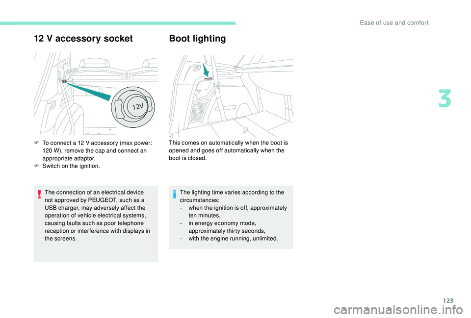
12 V accessory socket
The connection of an electrical device
not approved by PEUGEOT, such as a
USB charger, may adversely affect the
operation of vehicle electrical systems,
causing faults such as poor telephone
reception or inter ference with displays in
the screens.
Boot lighting
F To connect a 12 V accessory (max power:
120 W), remove the cap and connect an
appropriate adaptor.
F
S
witch on the ignition. This comes on automatically when the boot is
opened and goes off automatically when the
boot is closed.
The lighting time varies according to the
circumstances:
-
w
hen the ignition is off, approximately
ten minutes,
-
i
n energy economy mode,
approximately thirty seconds,
-
w
ith the engine running, unlimited.
3
Ease of use and comfort
Page 130 of 404
128
Headlamp adjustment
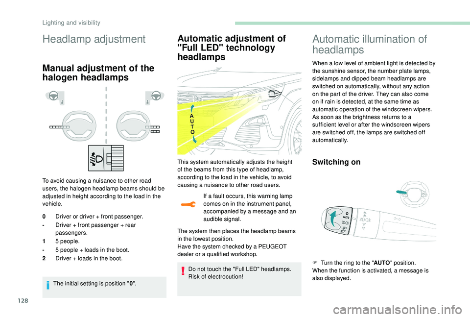
Manual adjustment of the
halogen headlamps
To avoid causing a nuisance to other road
users, the halogen headlamp beams should be
adjusted in height according to the load in the
vehicle.The initial setting is position " 0".
Automatic adjustment of
"Full LED" technology
headlamps
If a fault occurs, this warning lamp
comes on in the instrument panel,
accompanied by a message and an
audible signal.
The system then places the headlamp beams
in the lowest position.
Have the system checked by a PEUGEOT
dealer or a qualified workshop.
Do not touch the "Full LED" headlamps.
Risk of electrocution!
0
Driver or driver + front passenger.
- Driver + front passenger + rear
passengers.
1 5
people.
- 5
people + loads in the boot.
2 Driver + loads in the boot.
Automatic illumination of
headlamps
When a low level of ambient light is detected by
the sunshine sensor, the number plate lamps,
sidelamps and dipped beam headlamps are
switched on automatically, without any action
on the part of the driver. They can also come
on if rain is detected, at the same time as
automatic operation of the windscreen wipers.
As soon as the brightness returns to a
sufficient level or after the windscreen wipers
are switched off, the lamps are switched off
automatically.
Switching onThis system automatically adjusts the height
of the beams from this type of headlamp,
according to the load in the vehicle, to avoid
causing a nuisance to other road users.
F
T
urn the ring to the "AUTO" position.
When the function is activated, a message is
also displayed.
Lighting and visibility
Page 152 of 404
150
Locking
F Pull the strap then insert the tongue in the buckle.
F
C
heck that the seat belt is fastened
correctly by pulling the strap.
Unlocking
F Press the red button on the buckle.
F G uide the seat belt as it is reeled in.
2nd row rear central seat
belt
The seat belt for the rear central position is
integrated into the roof.
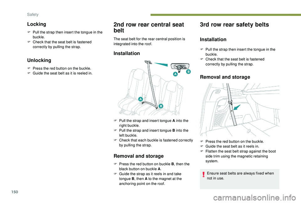
Installation
Removal and storage
F Press the red button on buckle B , then the
black button on buckle A .
F
G
uide the strap as it reels in and take
tongue B , then A to the magnet at the
anchoring point on the roof.
3rd row rear safety belts
Installation
F Pull the strap then insert the tongue in the buckle.
F
C
heck that the seat belt is fastened
correctly by pulling the strap.
Removal and storage
Ensure seat belts are always fixed when
not in use.
F
P
ull the strap and insert tongue A into the
right buckle.
F
P
ull the strap and insert tongue B into the
left buckle.
F
C
heck that each buckle is fastened correctly
by pulling the strap. F
P
ress the red button on the buckle.
F
G
uide the seat belt as it reels in.
F
F
latten the seat belt strap against the boot
side trim using the magnetic retaining
system.
Safety
Page 254 of 404
252
Apply the label provided to a clearly visible
area, close to the carrier or in the boot.
Go to a PEUGEOT dealer or a qualified
workshop for any work on the towbar
system.
Load reduction mode
System which manages the use of certain
functions according to the level of charge
remaining in the battery.
When the vehicle is being driven, the load
reduction function temporarily deactivates
certain functions, such as air conditioning,
heated rear screen, etc.
The deactivated functions are reactivated
automatically as soon as conditions permit.
Maintenance
Correct operation is only possible if the towball
and its carrier are kept clean.
Before cleaning the vehicle with a high-
pressure jet wash, the towball must be removed
and the protective plug fitted to the carrier.
Energy economy mode
System which manages the duration of use of
certain functions to conser ve a sufficient level
of charge in the battery.
After the engine has stopped, you can still use
functions such as the audio and telematics
system, windscreen wipers, dipped beam
headlamps, courtesy lamps, etc. for a
maximum combined duration of about forty
minutes.
Switching to this mode
A message appears in the instrument panel
screen indicating that the vehicle has switched
to economy mode and the active functions are
put on standby.If a telephone call is being made at this
time, it will be maintained for around
10
minutes with the Bluetooth hands-free
system of your audio system.
Exiting the mode
These functions will be automatically restored
the next time the vehicle is used.
In order to restore the use of these functions
immediately, start the engine and let it run:
-
f
or less than ten minutes, to use the
equipment for approximately five minutes,
-
f
or more than ten minutes, to use the
equipment for up to approximately thirty
minutes.
Let the engine run for the duration specified to
ensure that the battery charge is sufficient.
Do not repeatedly and continuously restart the
engine in order to charge the battery.
A flat battery prevents the engine from
starting.
For more information on the 12
V batter y,
refer to the corresponding section.
Practical information
Page 269 of 404
267
Engine 2.0 HDi
F Fill the fuel tank with at least five litres of Diesel.
F
O
pen the bonnet.
F
I
f necessary, unclip the cover to access the
priming pump.
F
L
oosen the degassing bolt.
F
U
se the priming pump until fuel appears in
the transparent tube.
F
R
etighten the degassing bolt.
F
O
perate the starter until the engine starts (if
the engine does not start at the first attempt,
wait around 15
seconds before trying
again).
F
I
f the engine does not start after a few
attempts, operate the priming pump again
then start the engine.
F
P
ut it back in place, clip in the cover and
ensure it is clipped in.
F
C
lose the boot again.
Tool kit
This is a set of tools provided with the vehicle.
Its content depends on your vehicle's
equipment:
-
t
emporary puncture repair kit,
-
spar
e wheel.
List of tools
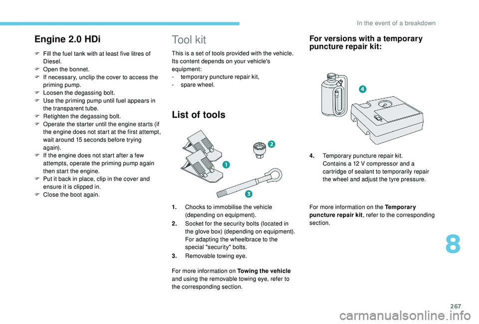
1.Chocks to immobilise the vehicle
(depending on equipment).
2. Socket for the security bolts (located in
the glove box) (depending on equipment).
For adapting the wheelbrace to the
special "security" bolts.
3. Removable towing eye.
For more information on Towing the vehicle
and using the removable towing eye, refer to
the corresponding section.
For versions with a temporary
puncture repair kit:
For more information on the Temporary
puncture repair kit , refer to the corresponding
section. 4. Temporary puncture repair kit.
Contains a 12 V compressor and a
cartridge of sealant to temporarily repair
the wheel and adjust the tyre pressure.
8
In the event of a breakdown
Page 270 of 404
268
For more information on the Spare wheel, refer
to the corresponding section. All of these tools are specific to your
vehicle and may vary depending on
equipment.
Do not use them for any other purposes.
The jack must only be used to change
a wheel with a damaged or punctured tyre.
Do not use any jack other than the one
supplied with this vehicle.
If the vehicle does not have its original
jack, contact a PEUGEOT dealer or a
qualified workshop to obtain the correct
jack for it.
The jack meets European standards,
as defined in the Machinery Directive
2006/42/CE.
The jack does not require any
maintenance.
Access to the tools
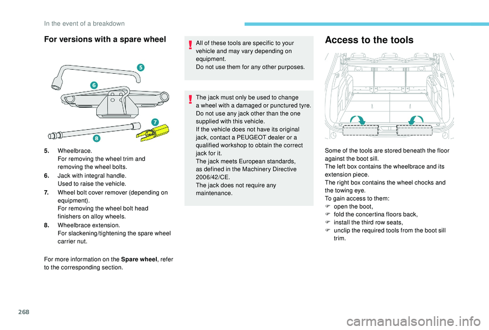
Some of the tools are stored beneath the floor
against the boot sill.
The left box contains the wheelbrace and its
extension piece.
The right box contains the wheel chocks and
the towing eye.
To gain access to them:
F
o
pen the boot,
F
f
old the concertina floors back,
F
i
nstall the third row seats,
F
u
nclip the required tools from the boot sill
trim.
For versions with a spare wheel
5. Wheelbrace.
For removing the wheel trim and
removing the wheel bolts.
6. Jack with integral handle.
Used to raise the vehicle.
7. Wheel bolt cover remover (depending on
equipment).
For removing the wheel bolt head
finishers on alloy wheels.
8. Wheelbrace extension.
For slackening/tightening the spare wheel
carrier nut.
In the event of a breakdown
Page 273 of 404
271
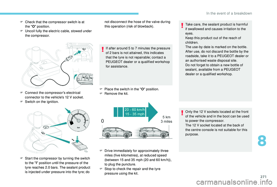
F Check that the compressor switch is at the " O" position.
F
U
ncoil fully the electric cable, stowed under
the compressor.
If after around 5
to 7 minutes the pressure
of 2
bars is not attained, this indicates
that the tyre is not repairable; contact a
PEUGEOT dealer or a qualified workshop
for assistance.
F
P
lace the switch in the "O" position.
F
R
emove the kit.Take care, the sealant product is harmful
if swallowed and causes irritation to the
eyes.
Keep this product out of the reach of
children.
The use-by date is marked on the bottle.
After use, do not discard the bottle by the
roadside, take it to a PEUGEOT dealer or
an authorised waste disposal site.
Do not forget to obtain a new bottle of
sealant, available from a PEUGEOT
dealer or a qualified workshop.
F
C
onnect the compressor's electrical
connector to the vehicle's 12
V socket.
F
S
witch on the ignition.
F
S
tart the compressor by turning the switch
to the " l" position until the pressure of the
tyre reaches 2.0
bars. The sealant product
is injected under pressure into the tyre; do not disconnect the hose of the valve during
this operation (risk of blowback).
F
D
rive immediately for approximately three
miles (five kilometres), at reduced speed
(between 15
and 35 mph (20 and 60 km/h)),
to plug the puncture.
F
S
top to check the repair and the tyre
pressure using the kit. Only the 12
V sockets located at the front
of the vehicle and in the boot can be used
to power the compressor.
The 12
V socket located at the back of
the centre console is not suitable for this
purpose.
8
In the event of a breakdown
Page 276 of 404
274
Tool storage
The punctured wheel cannot be stored
beneath the vehicle.
It must be placed in the boot. Use a pad to
protect the inside of the boot.
Putting the winch and spare
wheel back in place
When the spare wheel is fitted in place of
a wheel with a punctured tyre, the winch
and tool box must be placed beneath the
vehicle again before restarting.
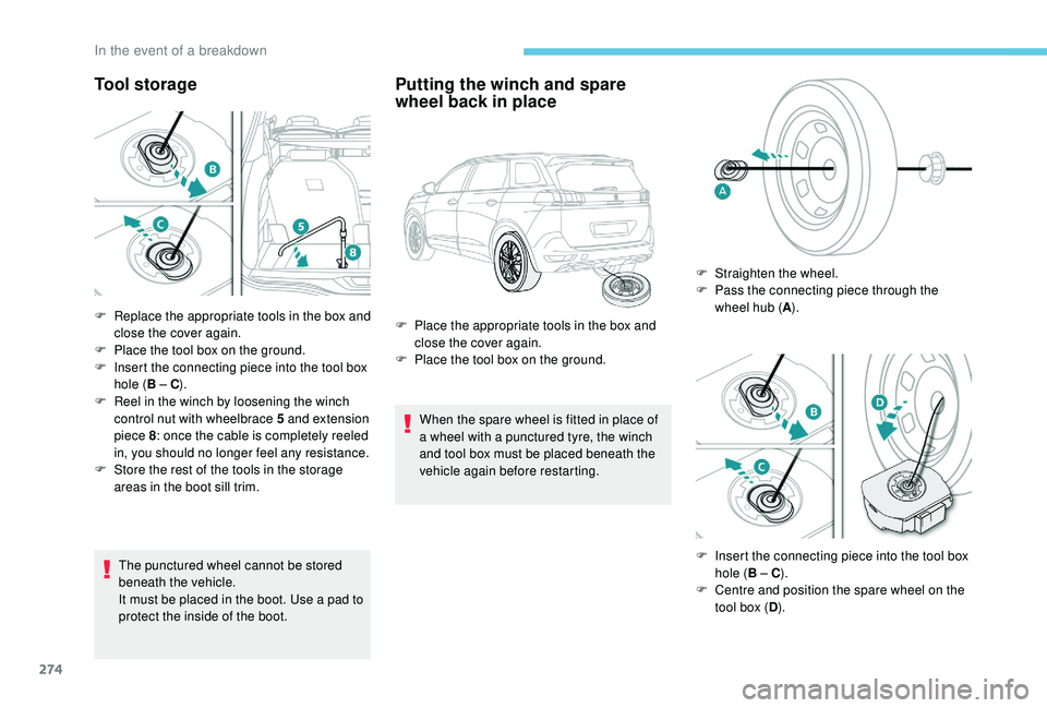
F
R
eplace the appropriate tools in the box and
close the cover again.
F
P
lace the tool box on the ground.
F
I
nsert the connecting piece into the tool box
hole ( B – C).
F
R
eel in the winch by loosening the winch
control nut with wheelbrace 5
and extension
piece 8 : once the cable is completely reeled
in, you should no longer feel any resistance.
F
S
tore the rest of the tools in the storage
areas in the boot sill trim. F
P
lace the appropriate tools in the box and
close the cover again.
F
P
lace the tool box on the ground. F
S
traighten the wheel.
F
P
ass the connecting piece through the
wheel hub ( A).
F
I
nsert the connecting piece into the tool box
hole ( B – C).
F
C
entre and position the spare wheel on the
tool box ( D).
In the event of a breakdown