Page 70 of 566

68
3008-2_en_Chap02_ouvertures_ed01-2016
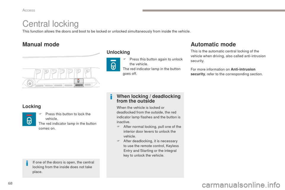
Central locking
Manual mode
Unlocking
This function allows the doors and boot to be locked or unlocked simultaneously from inside the vehicle.
LockingWhen locking / deadlocking
from the outsideWhen the vehicle is locked or
deadlocked from the outside, the red
indicator lamp flashes and the button is
inactive.
F
A
fter normal locking, pull one of the
interior door levers to unlock the
vehicle.
F
A
fter deadlocking, it is necessary
to use the remote control, Keyless
Entry and Starting or the integral
key to unlock the vehicle.
Automatic mode
This is the automatic central locking of the
vehicle when driving, also called anti-intrusion
s e c u r i t y.
For more information on Anti-intrusion
security , refer to the corresponding section.
If one of the doors is open, the central
locking from the inside does not take
place. F
P
ress this button to lock the
vehicle.
The red indicator lamp in the button
comes on. F
P
ress this button again to unlock
the vehicle.
The red indicator lamp in the button
goes off.
Access
Page 71 of 566

69
3008-2_en_Chap02_ouvertures_ed01-2016
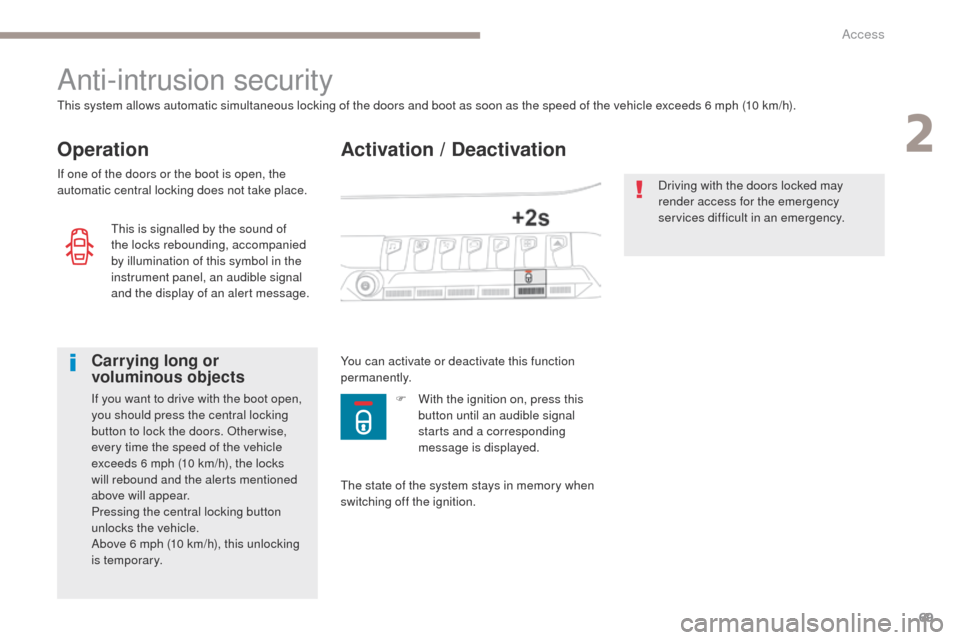
Activation / Deactivation
Anti-intrusion security
Operation
This system allows automatic simultaneous locking of the doors and boot as soon as the speed of the vehicle exceeds 6 mph (10 km/h).
If one of the doors or the boot is open, the
automatic central locking does not take place.
Carrying long or
voluminous objects
If you want to drive with the boot open,
you should press the central locking
button to lock the doors. Other wise,
every time the speed of the vehicle
exceeds 6 mph (10 km/h), the locks
will rebound and the alerts mentioned
above will appear.
Pressing the central locking button
unlocks the vehicle.
Above 6 mph (10 km/h), this unlocking
is temporary.You can activate or deactivate this function
permanently.
Driving with the doors locked may
render access for the emergency
services difficult in an emergency.
This is signalled by the sound of
the locks rebounding, accompanied
by illumination of this symbol in the
instrument panel, an audible signal
and the display of an alert message.
The state of the system stays in memory when
switching off the ignition.F
W ith the ignition on, press this
button until an audible signal
starts and a corresponding
message is displayed.
2
Access
Page 94 of 566

92
3008-2_en_Chap03_ergonomie-et-confort_ed01-2016
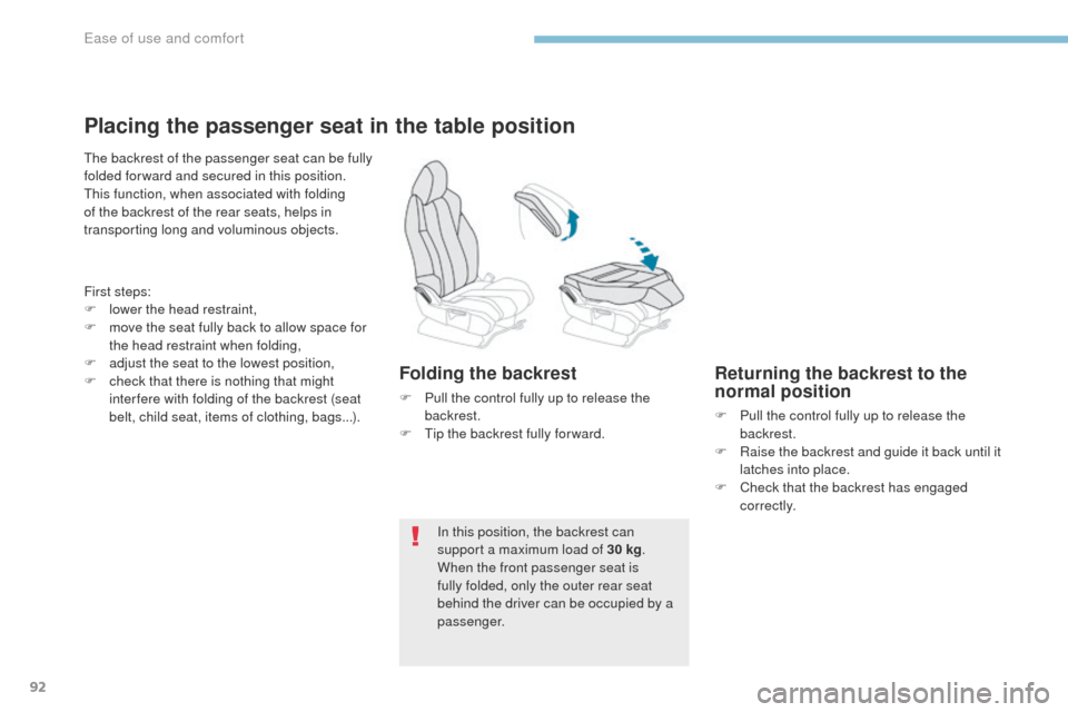
Placing the passenger seat in the table position
The backrest of the passenger seat can be fully
folded for ward and secured in this position.
This function, when associated with folding
of the backrest of the rear seats, helps in
transporting long and voluminous objects.
First steps:
F
l
ower the head restraint,
F
m
ove the seat fully back to allow space for
the head restraint when folding,
F
a
djust the seat to the lowest position,
F
c
heck that there is nothing that might
inter fere with folding of the backrest (seat
belt, child seat, items of clothing, bags...).
Folding the backrest
F Pull the control fully up to release the backrest.
F
T
ip the backrest fully for ward.
In this position, the backrest can
support a maximum load of 30 kg .
When the front passenger seat is
fully folded, only the outer rear seat
behind the driver can be occupied by a
passenger.
Returning the backrest to the
normal position
F Pull the control fully up to release the backrest.
F
R
aise the backrest and guide it back until it
latches into place.
F
C
heck that the backrest has engaged
c o r r e c t l y.
Ease of use and comfort
Page 95 of 566

93
3008-2_en_Chap03_ergonomie-et-confort_ed01-2016
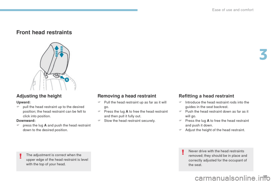
Front head restraints
Adjusting the height
Upward:
F p ull the head restraint up to the desired
position; the head restraint can be felt to
click into position.
Downward:
F
p
ress the lug A and push the head restraint
down to the desired position.
The adjustment is correct when the
upper edge of the head restraint is level
with the top of your head.
Removing a head restraint
F Pull the head restraint up as far as it will go.
F
P
ress the lug A to free the head restraint
and then pull it fully out.
F
S
tow the head restraint securely.
Refitting a head restraint
F Introduce the head restraint rods into the guides in the seat backrest.
F
P
ush the head restraint down as far as it
will go.
F
P
ress the lug A to free the head restraint
and push it down.
F
A
djust the height of the head restraint.Never drive with the head restraints
removed; they should be in place and
correctly adjusted for the occupant of
the seat.
3
Ease of use and comfort
Page 129 of 566
127
3008-2_en_Chap03_ergonomie-et-confort_ed01-2016
Mats
When fitting the mat for the first time, on the
driver's side use only the fixings provided in the
wallet attached.
The other mats are simply placed on the
carpet.
Removal
Refitting
To avoid any risk of jamming of the
pedals:
-
o
nly use mats which are suited to
the fixings already present in the
vehicle; these fixings must be used,
-
n
ever fit one mat on top of another.
The use of mats not approved by
PEUGEOT may inter fere with access to
the pedals and hinder the operation of
the cruise control / speed limiter.
The mats approved by PEUGEOT have
two fixings located below the seat.
Fitting
To remove the mat on the driver's side:
F m ove the seat as far back as possible,
F
un
clip the fixings,
F
r
emove the mat.
To refit the mat on the driver's side:
F
p
osition the mat correctly,
F
r
efit the fixings by pressing,
F
c
heck that the mat is secured correctly.
3
Ease of use and comfort
Page 137 of 566
135
3008-2_en_Chap03_ergonomie-et-confort_ed01-2016
Boot fittings
1. Load space cover
2. 12 V accessor y socket (120 W)
3.
B
oot lamp
4.
R
ear seat folding controls
5.
Hoo
ks
6.
S
towing rings
7.
A
djustable boot floor (2 positions )
8.
S
torage well / Tool box under the floorThe stowing rings are designed for
securing luggage by attaching a
retaining net to the rings.
Such nets are available as an option or
as an accessory.
For more information, contact a
PEUGEOT dealer.
For the installation of a high load
retaining net, refer to the corresponding
section.
3
Ease of use and comfort
Page 158 of 566

156
3008-2_en_Chap05_securite_ed01-2016
General safety recommendations
Labels are applied at various
points on your vehicle. They carry
safety warnings as well as vehicle
identification information. Do not
remove them: they form an integral part
of your vehicle.
For any work on your vehicle, use
a qualified workshop that has the
technical information, skills and
equipment required, all of which a
PEUGEOT dealer is able to provide.We draw your attention to
the following points:
- The fitting of electrical equipment or accessories not listed by
PEUGEOT
may cause excessive
current consumption and faults and
failures with the electrical system of
your vehicle. Contact a PEUGEOT
dealer for information on the range
of recommended accessories.
-
A
s a safety measure, access to
the diagnostic socket, used for
the vehicle's electronic systems,
is reserved strictly for PEUGEOT
dealers or qualified workshops,
equipped with the special tools
required (risk of malfunctions of the
vehicle's electronic systems that
could cause breakdowns or serious
accidents). The manufacturer
cannot be held responsible if this
advice is not followed.
-
A
ny modification or adaptation
not intended or authorised by
Automobiles PEUGEOT or
carried out without meeting the
technical requirements defined
by the manufacturer would lead
to the suspension of the legal and
contractual warranties.
Installation of accessory
radio communication
transmitters
Before installing a radio communication
transmitter, you must contact a
PEUGEOT dealer for the specification
of transmitters which can be fitted
(frequency, maximum power,
aerial position, specific installation
requirements), in line with the Vehicle
Electromagnetic Compatibility
Directive
(2004/104/EC).
Depending on the legislation in force in
the country, certain safety equipment
may be compulsory: high visibility
safety vests, warning triangles,
breathalysers, spare bulbs, spare fuses,
fire extinguisher, first aid kit, mud flaps
at the rear of the vehicle...
Safety
Page 159 of 566
157
3008-2_en_Chap05_securite_ed01-2016
Hazard warning lamps
Visual warning with all of the direction
indicators flashing to alert other road users to a
vehicle breakdown, towing or accident.
F
P
ress this button, all of the direction
indicators flash.
They can operate with the ignition off.
Automatic operation of
hazard warning lamps
When braking in an emergency, depending on
the force of deceleration, the hazard warning
lamps come on automatically. They switch off
automatically the first time you accelerate.
It is also possible to switch them off by pressing
the switch on the dashboard.
Horn
Audible warning to alert other road users to an
imminent danger.
F
P
ress the central part of the multifunction
steering wheel.
5
Safety