2017 NISSAN QUEST mirror
[x] Cancel search: mirrorPage 188 of 520
settings. (See “Vehicle information and settings
(models with center multi-function control pa-
nel)” (P.4-10) .)
Initialize entry/exit function
If the battery cable is disconnected, or if the fuse
opens, the entry/exit function will not work
though this function was set on before. In such
a case, after connecting the battery or replacing
with a new fuse, open and close the driver’s
door more than two times after the ignition
switch is placed in the LOCK position from the
ON position. The entry/exit function will be
activated.
JVP0248X
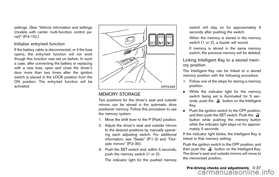
MEMORY STORAGE
Two positions for the driver’s seat and outside
mirrors can be stored in the automatic drive
positioner memory. Follow this procedure to use
the memory system.
1. Move the shift lever to the P (Park) position.
2. Adjust the driver’s seat and outside mirrorsto the desired positions by manually operat-
ing each adjusting switch. For additional
information, see “Seats” (P.1-2) and “Out-
side mirrors” (P.3-35) .
3. Push the SET switch and, within 5 seconds, push the memory switch (1 or 2) .
The indicator light for the pushed memory switch will stay on for approximately 5
seconds after pushing the switch.
When the memory is stored in the memory
switch (1 or 2) , a buzzer will sound.
If memory is stored in the same memory
switch, the previous memory will be deleted.
Linking Intelligent Key to a stored mem-
ory position
The Intelligent Key can be linked to a stored
memory position with the following procedure.
1. Follow one of the steps for storing a memory
position.
. While the indicator light for the memory
switch being set is illuminated for 5 sec-
onds, push the
button on the Intelligent
Key.
. Push the ignition switch to the OFF position,
and then push the SET switch. Push the
button while pushing the memory button
while the indicator light stays on for approxi-
mately 5 seconds.
If the indicator light blinks, the Intelligent Key is
linked to that memory setting.
Push the ignition switch to the OFF position, and
then push the
button on the Intelligent Key.
The driver’s seat and outside mirrors will move to
the memorized position.
Pre-driving checks and adjustments3-37
Page 189 of 520
3-38Pre-driving checks and adjustments
Confirming memory storage
.Push the ignition switch to the ON position
and push the SET switch. If the main
memory has not been stored, the indicator
light will come on for approximately 0.5
second. When the memory has stored in
position, the indicator light will stay on for
approximately 5 seconds.
. If the battery cable is disconnected, or if the
fuse opens, the memory will be canceled. In
this case, reset the desired position using
the previous procedure.
. If optional keys are added to your vehicle,
the memory storage procedure to switch 1
or 2 and linking Intelligent Key procedure to
a stored memory position should be per-
formed again for each Intelligent Key. For
additional Intelligent Key information, see
“Keys” (P.3-3) .
Selecting the memorized position
1. Move the shift lever to the P (Park) position.
2. Use one of the following methods to move
the driver’s seat and outside mirrors.
.Push the memory switch (1 or 2) ..Within 45 seconds of opening thedriver’s door, push the memory switch
(1 or 2) .
The driver’s seat and outside mirrors will move to the memorized position with the
indicator light flashing, and then the light will
stay on for approximately 5 seconds.
SYSTEM OPERATION
The automatic drive positioner system will not
work or will stop operating under the following
conditions:
.
When the vehicle speed is above 4 MPH (7
km/h) (entry/exit function) .
. When the vehicle is driven (memory sto-
rage) .
. When the adjusting switch for the driver’s
seat is turned on while the automatic drive
positioner is operating.
. When the driver’s seat and outside mirrors
have already been moved to the memorized
position.
. When no position is stored in the memory
switch.
. When the engine is started while moving the
automatic drive positioner.
. When the shift lever is moved from the P
(Park) position to any other position. (How-
ever, it will not be canceled while the driver’s
seat is returning to the previous positions
(entry/exit function) .)
. When the driver’s door remains open for
more than 45 seconds and the ignition switch is not in the ON position.
Page 214 of 520
WARNING
Failure to follow the warnings and
instructions for proper use of the Rear-
View Monitor system could result in
serious injury or death.
.The RearView Monitor is a conve-
nience but it is not a substitute for
proper backing. Always turn and
look out the windows, and check
mirrors to be sure that it is safe to
move before operating the vehicle.
Always back up slowly.
. The system is designed as an aid to
the driver in showing large station-
ary objects directly behind the vehi-
cle, to help avoid damaging the
vehicle.
. The distance guide line and the
vehicle width line should be used
as a reference only when the vehicle
is on a level paved surface. The
distance viewed on the monitor is
for reference only and may be
different than the actual distance
between the vehicle and displayed
objects.
CAUTION
Do not scratch the camera lens when
cleaning dirt or snow from the front of
the camera.
The RearView Monitor system automatically
shows a rear view of the vehicle when the shift
lever is placed in the R (Reverse) position.
The radio can still be heard while the RearView
Monitor is active.
JVH1274X
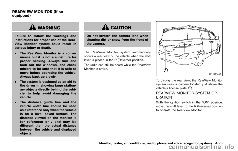
To display the rear view, the RearView Monitor
system uses a camera located just above the
vehicle’s license plate
*1.
REARVIEW MONITOR SYSTEM OP-
ERATION
With the ignition switch in the “ON” position,
move the shift lever to the R (Reverse) position
to operate the RearView Monitor.
Monitor, heater, air conditioner, audio, phone and voice recognition systems4-25
REARVIEW MONITOR (if so
equipped)
Page 219 of 520
4-30Monitor, heater, air conditioner, audio, phone and voice recognition systems
REARVIEW MONITOR SYSTEM LIM-
ITATIONS
WARNING
Listed below are the system limitations
for RearView Monitor. Failure to oper-
ate the vehicle in accordance with these
system limitations could result in ser-
ious injury or death.
.The system cannot completely elim-
inate blind spots and may not show
every object.
. Underneath the bumper and the
corner areas of the bumper cannot
be viewed on the RearView Monitor
because of its monitoring range
limitation. The system will not show
small objects below the bumper,
and may not show objects close to
the bumper or on the ground.
. Objects viewed in the RearView
Monitor differ from actual distance
because a wide-angle lens is used.
. Objects in the RearView Monitor
will appear visually opposite com-
pared to when viewed in the rear
view and outside mirrors. .
Use the displayed lines as a refer-
ence. The lines are highly affected
by the number of occupants, fuel
level, vehicle position, road condi-
tions and road grade.
. Make sure that the liftgate is se-
curely closed when backing up.
. Do not put anything on the rearview
camera. The rearview camera is
installed above the license plate.
. When washing the vehicle with
high-pressure water, be sure not to
spray it around the camera. Other-
wise, water may enter the camera
unit causing water condensation on
the lens, a malfunction, fire or an
electric shock.
. Do not strike the camera. It is a
precision instrument. Otherwise, it
may malfunction or cause damage
resulting in a fire or an electric
shock.
The following are operating limitations and do
not represent a system malfunction:
. When the temperature is extremely high or
low, the screen may not clearly display
objects. .
When strong light is directly coming on the
camera, objects may not be displayed
clearly.
. Vertical lines may be seen in objects on the
screen. This is due to strong reflected light
from the bumper.
. The screen may flicker under fluorescent
light.
. The colors of objects on the RearView
Monitor may differ somewhat from the actual
color of objects.
. Objects on the monitor may not be clear in a
dark environment.
. If dirt, rain or snow accumulates on the
camera, the RearView Monitor may not
display objects clearly. Clean the camera.
. Do not use wax on the camera window.
Wipe off any wax with a clean cloth
dampened with mild detergent diluted with
water.
Page 222 of 520
Available views:
.Front View
The view to the front of the vehicle.
. Rear View
The view to the rear of the vehicle.
. Bird’s-Eye View
The surrounding view of the vehicle.
. Front-side View
The view around and ahead of the front
passenger’s side wheel.
JVH1524X
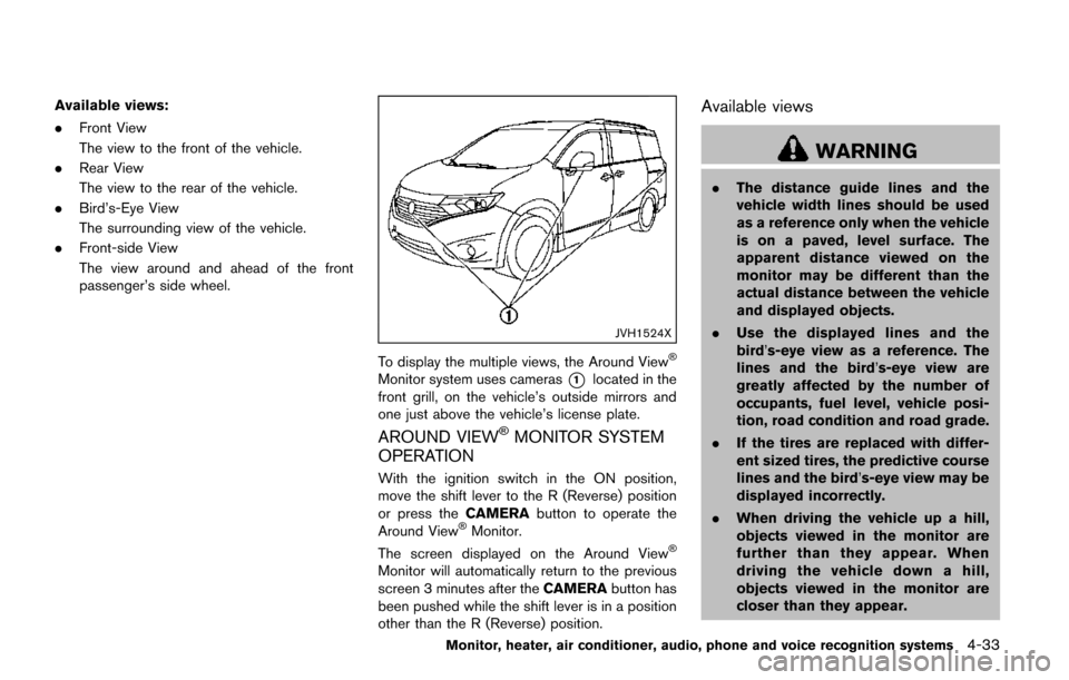
To display the multiple views, the Around View�Š
Monitor system uses cameras*1located in the
front grill, on the vehicle’s outside mirrors and
one just above the vehicle’s license plate.
AROUND VIEW�ŠMONITOR SYSTEM
OPERATION
With the ignition switch in the ON position,
move the shift lever to the R (Reverse) position
or press the CAMERAbutton to operate the
Around View
�ŠMonitor.
The screen displayed on the Around View�Š
Monitor will automatically return to the previous
screen 3 minutes after the CAMERAbutton has
been pushed while the shift lever is in a position
other than the R (Reverse) position.
Available views
WARNING
. The distance guide lines and the
vehicle width lines should be used
as a reference only when the vehicle
is on a paved, level surface. The
apparent distance viewed on the
monitor may be different than the
actual distance between the vehicle
and displayed objects.
. Use the displayed lines and the
bird’s-eye view as a reference. The
lines and the bird’s-eye view are
greatly affected by the number of
occupants, fuel level, vehicle posi-
tion, road condition and road grade.
. If the tires are replaced with differ-
ent sized tires, the predictive course
lines and the bird’s-eye view may be
displayed incorrectly.
. When driving the vehicle up a hill,
objects viewed in the monitor are
further than they appear. When
driving the vehicle down a hill,
objects viewed in the monitor are
closer than they appear.
Monitor, heater, air conditioner, audio, phone and voice recognition systems4-33
Page 223 of 520
4-34Monitor, heater, air conditioner, audio, phone and voice recognition systems
.Objects in the monitor will appear
visually opposite compared to when
viewed in the rear view and outside
mirrors.
. Use the mirrors or actually look to
properly judge distances to other
objects.
. The distance between objects
viewed in the rear view differs from
actual distance because a wide-
angle lens is used.
. On a snow-covered or slippery road,
there may be a difference between
the predictive course line and the
actual course line.
. The vehicle width and predictive
course lines are wider than the
actual width and course.
. The displayed lines on the rear view
will appear slightly off to the right
because the rear view camera is not
installed in the rear center of the
vehicle.
SAA1840
Front view
SAA1896Rear view
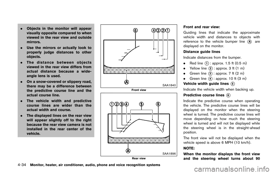
Front and rear view:
Guiding lines that indicate the approximate
vehicle width and distances to objects with
reference to the vehicle bumper line
*Aare
displayed on the monitor.
Distance guide lines
Indicate distances from the bumper.
. Red line
*1: approx. 1.5 ft (0.5 m)
. Yellow line
*2: approx. 3 ft (1 m)
. Green line
*3: approx. 7 ft (2 m)
. Green line
*4: approx. 10 ft (3 m)
Vehicle width guide lines
*5
Indicate the vehicle width when backing up.
Predictive course lines
*6
Indicate the predictive course when operating
the vehicle. The predictive course lines will be
displayed on the monitor when the steering
wheel is turned. The predictive course lines will
move depending on how much the steering
wheel is turned and will not be displayed while
the steering wheel is in the straight-ahead
position.
The front view will not be displayed when the
vehicle speed is above 6 MPH (10 km/h) .
NOTE:
When the monitor displays the front view
and the steering wheel turns about 90
Page 224 of 520
degrees or less from the straight ahead
position, both the right and left predictive
course lines
*6are displayed. When the
steering wheel turns about 90 degrees or
more, a line is displayed only on the
opposite side of the turn.
JVH0337X
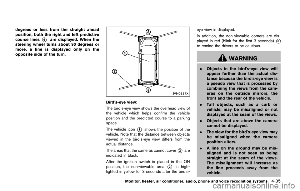
Bird’s-eye view:
The bird’s-eye view shows the overhead view of
the vehicle which helps confirm the vehicle
position and the predicted course to a parking
space.
The vehicle icon
*1shows the position of the
vehicle. Note that the distance between objects
viewed in the bird’s-eye view differs from the
actual distance.
The areas that the cameras cannot cover
*2are
indicated in black.
After the ignition switch is placed in the ON
position, the non-viewable area
*2is high-
lighted in yellow for 3 seconds after the bird’s- eye view is displayed.
In addition, the non-viewable corners are dis-
played in red (blink for the first 3 seconds)
*3
to remind the drivers to be cautious.
WARNING
.
Objects in the bird’s-eye view will
appear further than the actual dis-
tance because the bird’s-eye view is
a pseudo view that is processed by
combining the views from the cam-
eras on the outside mirrors, the
front and the rear of the vehicle.
. Tall objects, such as a curb or
vehicle, may be misaligned or not
displayed at the seam of the views.
. Objects that are above the camera
cannot be displayed.
. The view for the bird’s-eye view may
be misaligned when the camera
position alters.
. A line on the ground may be mis-
aligned and is not seen as being
straight at the seam of the views.
The misalignment will increase as
the line proceeds away from the
vehicle.
Monitor, heater, air conditioner, audio, phone and voice recognition systems4-35
Page 225 of 520
4-36Monitor, heater, air conditioner, audio, phone and voice recognition systems
.Tire angle display does not indicate
the actual tire angle.
JVH1141X
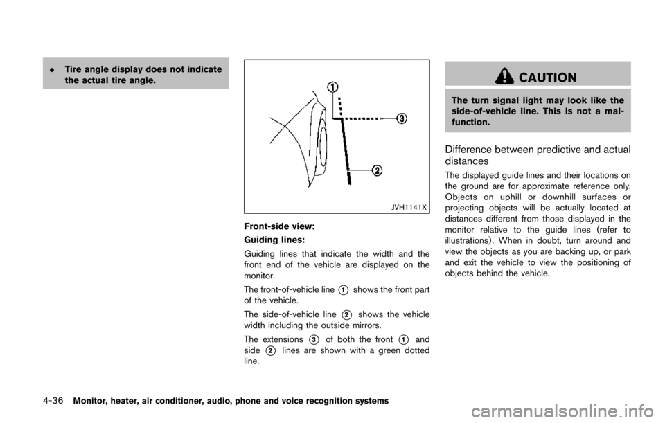
Front-side view:
Guiding lines:
Guiding lines that indicate the width and the
front end of the vehicle are displayed on the
monitor.
The front-of-vehicle line
*1shows the front part
of the vehicle.
The side-of-vehicle line
*2shows the vehicle
width including the outside mirrors.
The extensions
*3of both the front*1and
side
*2lines are shown with a green dotted
line.
CAUTION
The turn signal light may look like the
side-of-vehicle line. This is not a mal-
function.
Difference between predictive and actual
distances
The displayed guide lines and their locations on
the ground are for approximate reference only.
Objects on uphill or downhill surfaces or
projecting objects will be actually located at
distances different from those displayed in the
monitor relative to the guide lines (refer to
illustrations) . When in doubt, turn around and
view the objects as you are backing up, or park
and exit the vehicle to view the positioning of
objects behind the vehicle.