2017 NISSAN JUKE instrument panel
[x] Cancel search: instrument panelPage 120 of 416
SAA1232
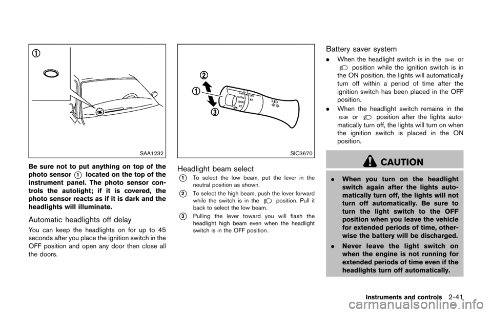
Be sure not to put anything on top of the
photo sensor
*1located on the top of the
instrument panel. The photo sensor con-
trols the autolight; if it is covered, the
photo sensor reacts as if it is dark and the
headlights will illuminate.
Automatic headlights off delay
You can keep the headlights on for up to 45
seconds after you place the ignition switch in the
OFF position and open any door then close all
the doors.
SIC3670
Headlight beam select
*1To select the low beam, put the lever in the
neutral position as shown.
*2To select the high beam, push the lever forward
while the switch is in theposition. Pull it
back to select the low beam.
*3Pulling the lever toward you will flash the
headlight high beam even when the headlight
switch is in the OFF position.
Battery saver system
. When the headlight switch is in theorposition while the ignition switch is in
the ON position, the lights will automatically
turn off within a period of time after the
ignition switch has been placed in the OFF
position.
. When the headlight switch remains in the
orposition after the lights auto-
matically turn off, the lights will turn on when
the ignition switch is placed in the ON
position.
CAUTION
. When you turn on the headlight
switch again after the lights auto-
matically turn off, the lights will not
turn off automatically. Be sure to
turn the light switch to the OFF
position when you leave the vehicle
for extended periods of time, other-
wise the battery will be discharged.
. Never leave the light switch on
when the engine is not running for
extended periods of time even if the
headlights turn off automatically.
Instruments and controls2-41
Page 122 of 416

Instrument brightness control
The instrument brightness control operates
when the ignition switch is in the ON position.
Push the control knob
*Ato adjust the bright-
ness of the instrument panel lights. The bright-
ness indicator
*Bwill be shown briefly in the
vehicle information display when the control is
turned.
When the brightness level reaches the maximum
or minimum, a beep will sound.
SIC3671
TURN SIGNAL SWITCH
*1Turn signal
Move the lever up or down to signal the turning
direction. When the turn is completed, the turn
signals cancel automatically.
*2Lane change signal
Move the lever up or down until the turn signal
begins to flash, but the lever does not latch, to
signal a lane change. Hold the lever until the lane
change is completed.
Move the lever up or down until the turn signal
begins to flash, but the lever does not latch, and
release the lever. The turn signal will automati-
cally flash three times. Choose the appropriate method to signal a lane
change based on road and traffic conditions.
Instruments and controls2-43
Page 125 of 416
2-46Instruments and controls
The heater is controlled by a thermostat,
automatically turning the heater on and off.
The indicator light will remain on as long as
the switch is on.
When the vehicle’s interior is warmed, or
before you leave the vehicle, be sure to turn
off the switch.
SIC4525
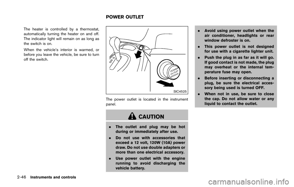
The power outlet is located in the instrument
panel.
CAUTION
.The outlet and plug may be hot
during or immediately after use.
. Do not use with accessories that
exceed a 12 volt, 120W (10A) power
draw. Do not use double adapters or
more than one electrical accessory.
. Use power outlet with the engine
running to avoid discharging the
vehicle battery. .
Avoid using power outlet when the
air conditioner, headlights or rear
window defroster is on.
. This power outlet is not designed
for use with a cigarette lighter unit.
. Push the plug in as far as it will go.
If good contact is not made, the plug
may overheat or the internal tem-
perature fuse may open.
. Before inserting or disconnecting a
plug, be sure the electrical acces-
sory being used is turned OFF.
. When not in use, be sure to close
the cap. Do not allow water or any
liquid to contact the outlet.
POWER OUTLET
Page 151 of 416
3-16Pre-driving checks and adjustments
JVP0338X
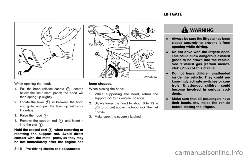
When opening the hood:
1. Pull the hood release handle
*1located
below the instrument panel; the hood will
then spring up slightly.
2. Locate the lever
*2in between the hood
and grille, and pull the lever up with your
fingertips.
3. Raise the hood
*3.
4. Remove the support rod
*4and insert it
into the slot
*5.
Hold the coated part
*Awhen removing or
resetting the support rod. Avoid direct
contact with the metal parts, as they may
be hot immediately after the engine has been stopped.
When closing the hood:
1. While supporting the hood, return the
support rod to its original position.
2. Slowly lower the hood to about 8 to 12 in (20 to 30 cm) above the hood lock, then let
it drop.
3. Make sure it is securely latched.
WARNING
. Always be sure the liftgate has been
closed securely to prevent it from
opening while driving.
. Do not drive with the liftgate open.
This could allow dangerous exhaust
gases to be drawn into the vehicle.
See “Exhaust gas (carbon monox-
ide)” (P.5-2) of this manual.
. Do not leave children unattended
inside the vehicle. They could un-
knowingly activate switches or con-
trols. Unattended children could
become involved in serious acci-
dents.
. Make sure that all passengers have
their hands, etc. inside the vehicle
before closing the liftgate.
LIFTGATE
Page 153 of 416
3-18Pre-driving checks and adjustments
SPA2336
OPENING THE FUEL-FILLER DOOR
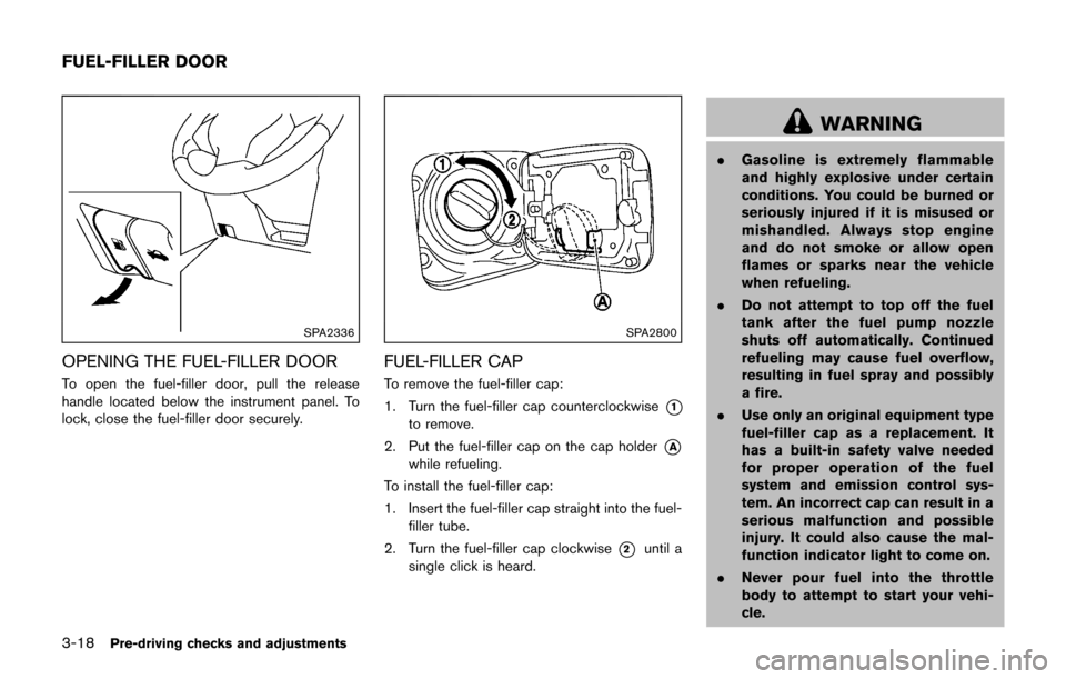
To open the fuel-filler door, pull the release
handle located below the instrument panel. To
lock, close the fuel-filler door securely.
SPA2800
FUEL-FILLER CAP
To remove the fuel-filler cap:
1. Turn the fuel-filler cap counterclockwise
*1
to remove.
2. Put the fuel-filler cap on the cap holder
*A
while refueling.
To install the fuel-filler cap:
1. Insert the fuel-filler cap straight into the fuel- filler tube.
2. Turn the fuel-filler cap clockwise
*2until a
single click is heard.
WARNING
. Gasoline is extremely flammable
and highly explosive under certain
conditions. You could be burned or
seriously injured if it is misused or
mishandled. Always stop engine
and do not smoke or allow open
flames or sparks near the vehicle
when refueling.
. Do not attempt to top off the fuel
tank after the fuel pump nozzle
shuts off automatically. Continued
refueling may cause fuel overflow,
resulting in fuel spray and possibly
a fire.
. Use only an original equipment type
fuel-filler cap as a replacement. It
has a built-in safety valve needed
for proper operation of the fuel
system and emission control sys-
tem. An incorrect cap can result in a
serious malfunction and possible
injury. It could also cause the mal-
function indicator light to come on.
. Never pour fuel into the throttle
body to attempt to start your vehi-
cle.
FUEL-FILLER DOOR
Page 157 of 416
3-22Pre-driving checks and adjustments
SPA2143
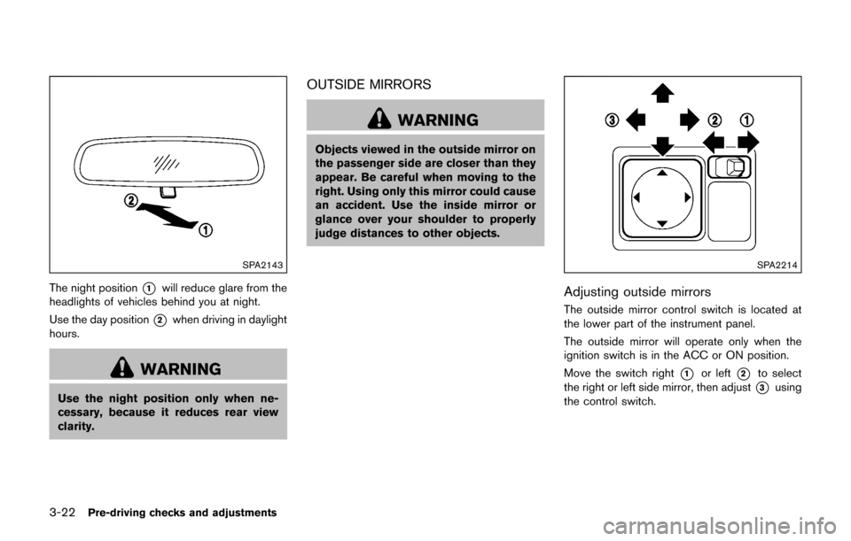
The night position*1will reduce glare from the
headlights of vehicles behind you at night.
Use the day position
*2when driving in daylight
hours.
WARNING
Use the night position only when ne-
cessary, because it reduces rear view
clarity.
OUTSIDE MIRRORS
WARNING
Objects viewed in the outside mirror on
the passenger side are closer than they
appear. Be careful when moving to the
right. Using only this mirror could cause
an accident. Use the inside mirror or
glance over your shoulder to properly
judge distances to other objects.
SPA2214
Adjusting outside mirrors
The outside mirror control switch is located at
the lower part of the instrument panel.
The outside mirror will operate only when the
ignition switch is in the ACC or ON position.
Move the switch right
*1or left*2to select
the right or left side mirror, then adjust
*3using
the control switch.
Page 173 of 416
4-14Heater, air conditioner, audio and phone systems
objects cannot be viewed. The four
corners of the vehicle in particular,
are areas where objects do not
always appear in the bird’s-eye,
front, or rear views. Always check
your surroundings to be sure that it
is safe to move before operating the
vehicle. Always operate the vehicle
slowly. Always look out the win-
dows and check mirrors to be sure
that it is safe to move.
. The driver is always responsible for
safety during parking and other
maneuvers.
CAUTION
Do not scratch the lens when cleaning
dirt or snow from the front of the
camera.
The Around View
�ŠMonitor system is designed
as an aid to the driver in situations such as slot
parking or parallel parking.
The monitor displays various views of the
position of the vehicle in a split screen format.
All views are not available at all times. Available views:
.
Bird’s-eye view
The surrounding view of the vehicle.
. Front-side view
The view around and ahead of the front
passenger’s side wheel.
. Front view
The view to the front of the vehicle.
. Rear view
The view to the rear of the vehicle.
JVH1224X
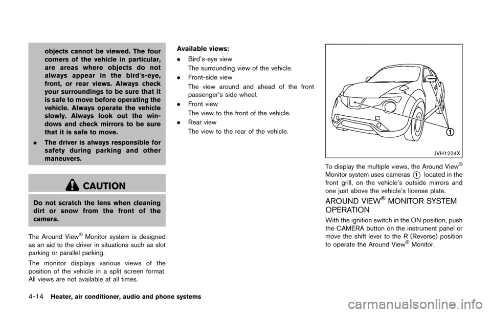
To display the multiple views, the Around View�Š
Monitor system uses cameras*1located in the
front grill, on the vehicle’s outside mirrors and
one just above the vehicle’s license plate.
AROUND VIEW�ŠMONITOR SYSTEM
OPERATION
With the ignition switch in the ON position, push
the CAMERA button on the instrument panel or
move the shift lever to the R (Reverse) position
to operate the Around View
�ŠMonitor.
Page 194 of 416
OPERATING TIPS (for automatic air
conditioner)
.When the engine coolant temperature and
outside air temperature are low, the air flow
from the foot outlets may not operate. This is
not a malfunction. After the coolant tem-
perature warms up, air will flow normally
from the foot outlets.
. The automatic air conditioner is equipped
with sensors as illustrated. The sensors
*A
and*Bon the instrument panel help
maintain a constant temperature. Do not
put anything on or around these sensors.
IN-CABIN MICROFILTER
The air conditioning system is equipped with an
in-cabin microfilter which collects dirt, pollen,
dust, etc. To make sure the air conditioner heats,
defogs, and ventilates efficiently, replace the
filter in accordance with the specified main-
tenance intervals listed in the “9. Maintenance
and schedules” section. It is recommended to
see a NISSAN dealer to replace the filter.
The filter should be replaced if the air flow
decreases significantly or if windows fog
up easily when operating the heater or air
conditioning system.
SERVICING AIR CONDITIONER
The air conditioner system in your vehicle is
charged with a refrigerant designed with the
environment in mind. This refrigerant will not
harm the earth’s ozone layer. Special char-
ging equipment and lubricant are required when
servicing your vehicle air conditioner. Using
improper refrigerants or lubricants will cause
severe damage to your air conditioner system.
(See “Capacities and recommended fluids/
lubricants” (P.10-2) for air conditioner system
refrigerant and lubricant recommendations.)
Your NISSAN dealer will be able to service your
environmentally friendly air conditioner system.
WARNING
The system contains refrigerant under
high pressure. To avoid personal injury,
any air conditioner service should be
done only by an experienced technician
with the proper equipment.
AUDIO OPERATION PRECAUTIONS
Radio
Place the ignition switch in the ACC or ON
position and push the FM·AM button to turn on
the radio. If you listen to the radio with the
engine not running, the ignition switch should be
placed in the ACC position.
Radio reception is affected by station signal
strength, distance from radio transmitter, build-
ings, bridges, mountains and other external
influences. Intermittent changes in reception
quality normally are caused by these external
influences.
Using a cellular phone in or near the
vehicle may influence radio reception
quality.
Radio reception:
Your vehicle radio system is equipped with
state-of-the-art electronic circuits to enhance
radio reception. These circuits are designed to
extend reception range, and to enhance the
quality of that reception.
However there are some general characteristics
of both FM and AM radio signals that can affect
radio reception quality in a moving vehicle, even
when the finest equipment is used. These
characteristics are completely normal in a given
reception area, and do not indicate any mal-
Heater, air conditioner, audio and phone systems4-35
AUDIO SYSTEM