2017 NISSAN ARMADA Center display
[x] Cancel search: Center displayPage 15 of 614
0-8Illustrated table of contents
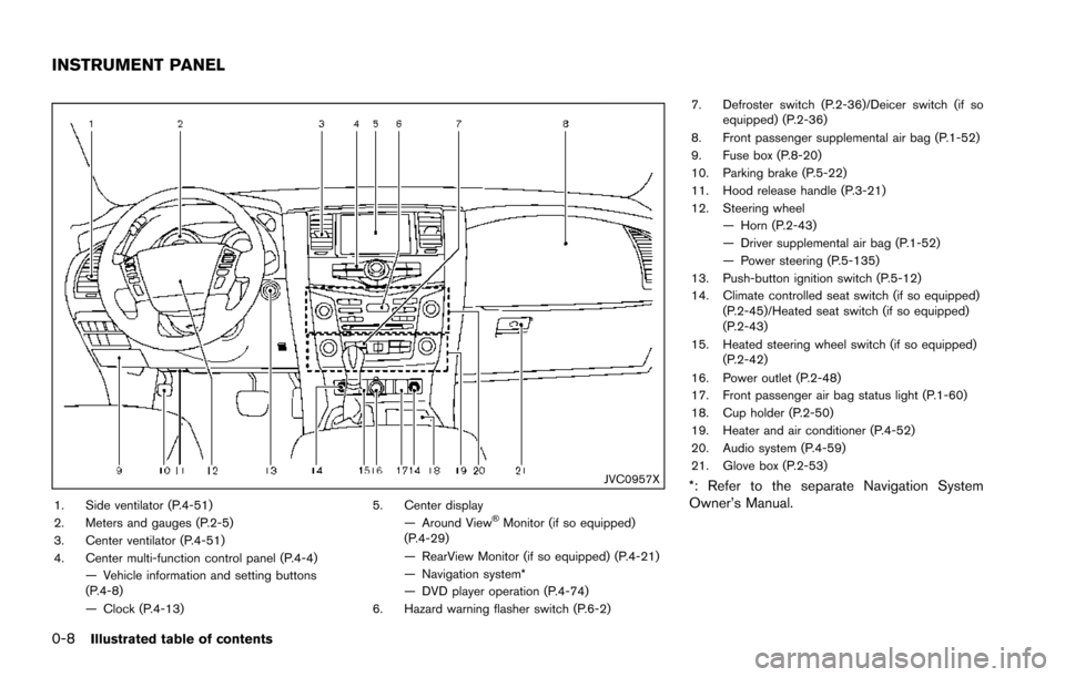
JVC0957X
1. Side ventilator (P.4-51)
2. Meters and gauges (P.2-5)
3. Center ventilator (P.4-51)
4. Center multi-function control panel (P.4-4)— Vehicle information and setting buttons
(P.4-8)
— Clock (P.4-13) 5. Center display
— Around View�ŠMonitor (if so equipped)
(P.4-29)
— RearView Monitor (if so equipped) (P.4-21)
— Navigation system*
— DVD player operation (P.4-74)
6. Hazard warning flasher switch (P.6-2) 7. Defroster switch (P.2-36)/Deicer switch (if so
equipped) (P.2-36)
8. Front passenger supplemental air bag (P.1-52)
9. Fuse box (P.8-20)
10. Parking brake (P.5-22)
11. Hood release handle (P.3-21)
12. Steering wheel — Horn (P.2-43)
— Driver supplemental air bag (P.1-52)
— Power steering (P.5-135)
13. Push-button ignition switch (P.5-12)
14. Climate controlled seat switch (if so equipped) (P.2-45)/Heated seat switch (if so equipped)
(P.2-43)
15. Heated steering wheel switch (if so equipped) (P.2-42)
16. Power outlet (P.2-48)
17. Front passenger air bag status light (P.1-60)
18. Cup holder (P.2-50)
19. Heater and air conditioner (P.4-52)
20. Audio system (P.4-59)
21. Glove box (P.2-53)
*: Refer to the separate Navigation System
Owner’s Manual.
INSTRUMENT PANEL
Page 93 of 614
2-4Instruments and controls
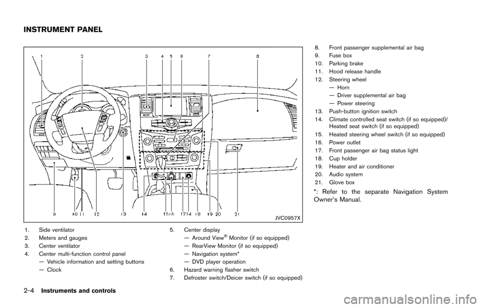
JVC0957X
1. Side ventilator
2. Meters and gauges
3. Center ventilator
4. Center multi-function control panel— Vehicle information and setting buttons
— Clock 5. Center display
— Around View�ŠMonitor (if so equipped)
— RearView Monitor (if so equipped)
— Navigation system*
— DVD player operation
6. Hazard warning flasher switch
7. Defroster switch/Deicer switch (if so equipped) 8. Front passenger supplemental air bag
9. Fuse box
10. Parking brake
11. Hood release handle
12. Steering wheel
— Horn
— Driver supplemental air bag
— Power steering
13. Push-button ignition switch
14. Climate controlled seat switch (if so equipped)/ Heated seat switch (if so equipped)
15. Heated steering wheel switch (if so equipped)
16. Power outlet
17. Front passenger air bag status light
18. Cup holder
19. Heater and air conditioner
20. Audio system
21. Glove box
*: Refer to the separate Navigation System
Owner’s Manual.
INSTRUMENT PANEL
Page 103 of 614
2-14Instruments and controls
recommended you visit a NISSAN
dealer for this service.
. If the 4WD warning light turns on
when driving on dry or hard surfaced
roads:
— in the 4H(I) position, shift the
4WD shift switch to AUTO
— in the 4L(O) position, stop the vehicle and shift the transmis-
sion shift lever to the N (Neutral)
position and shift the 4WD shift
switch to AUTO
. If the warning light is still on after
the above operations, have your
vehicle checked as soon as possi-
ble. It is recommended you visit a
NISSAN dealer for this service.
Forward Emergency Braking (FEB)
system warning light (if so equipped)
This light comes on when the ignition switch is
placed in the ON position. It turns off after the
engine is started.
This light illuminates when the Forward Emer-
gency Braking (FEB) system is set to OFF on
the center display.
If the light illuminates when the FEB system is ON, it may indicate that the system is unavail-
able. See “Forward Emergency Braking (FEB)”
(P.5-105) for more details.
Intelligent Cruise Control (ICC)
system warning light (orange; if so
equipped)
This light comes on if there is a malfunction in
the Intelligent Cruise Control (ICC) system.
If the warning light comes on, park the vehicle in
a safe place. Turn the engine off, restart the
engine, resume driving and set the ICC system
again.
If it is not possible to set the system or the
indicator stays on, it may indicate that the
system is malfunctioning. Although the
vehicle is still driveable under normal
conditions, have the vehicle checked. It is
recommended you visit a NISSAN dealer
for this service.
Intelligent Key warning light
After the ignition switch is placed in the ON
position, this light comes on for about 2 seconds
and then turns off.
This light warns of a malfunction with the
Intelligent Key system.
If the light comes on while the engine is stopped, it may be impossible to start the
engine. If the light comes on while the engine
is running, you can drive the vehicle. However in
these cases, it is recommended you visit a
NISSAN dealer for repair as soon as possible.
Lane Departure Warning (LDW)
indicator light (orange; if so equipped)
When the ignition switch is placed in the ON
position, the light will come on in orange, turn
green, and then turn off. This indicates that the
Lane Departure Warning (LDW) and Lane
Departure Prevention (LDP) systems are opera-
tional.
While the LDW and/or LDP system is on, the
light will blink in orange and a warning chime will
sound if the vehicle is traveling close to either
the left or the right of a traveling lane with
detectable lane markers.
If the light comes on in orange and remains on, it
may indicate that the LDW and LDP systems are
not functioning properly. Although the vehicle is
still driveable, have the systems checked. It is
recommended you visit a NISSAN dealer for this
service.
See “Lane Departure Warning (LDW)/Lane
Departure Prevention (LDP)” (P.5-23).
Page 115 of 614
2-26Instruments and controls
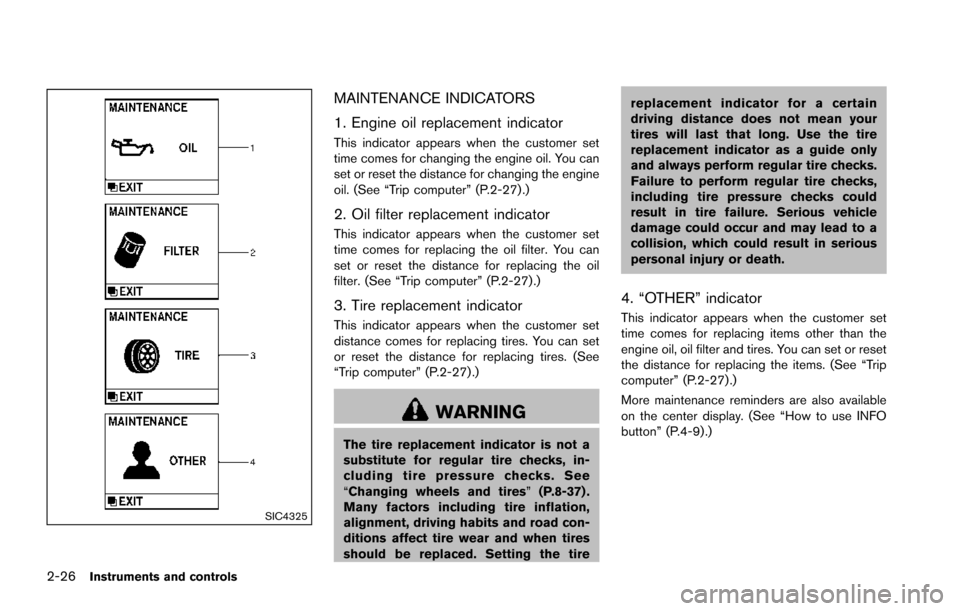
SIC4325
MAINTENANCE INDICATORS
1. Engine oil replacement indicator
This indicator appears when the customer set
time comes for changing the engine oil. You can
set or reset the distance for changing the engine
oil. (See “Trip computer” (P.2-27) .)
2. Oil filter replacement indicator
This indicator appears when the customer set
time comes for replacing the oil filter. You can
set or reset the distance for replacing the oil
filter. (See “Trip computer” (P.2-27).)
3. Tire replacement indicator
This indicator appears when the customer set
distance comes for replacing tires. You can set
or reset the distance for replacing tires. (See
“Trip computer” (P.2-27) .)
WARNING
The tire replacement indicator is not a
substitute for regular tire checks, in-
cluding tire pressure checks. See
“Changing wheels and tires”(P.8-37) .
Many factors including tire inflation,
alignment, driving habits and road con-
ditions affect tire wear and when tires
should be replaced. Setting the tire replacement indicator for a certain
driving distance does not mean your
tires will last that long. Use the tire
replacement indicator as a guide only
and always perform regular tire checks.
Failure to perform regular tire checks,
including tire pressure checks could
result in tire failure. Serious vehicle
damage could occur and may lead to a
collision, which could result in serious
personal injury or death.
4. “OTHER” indicator
This indicator appears when the customer set
time comes for replacing items other than the
engine oil, oil filter and tires. You can set or reset
the distance for replacing the items. (See “Trip
computer” (P.2-27).)
More maintenance reminders are also available
on the center display. (See “How to use INFO
button” (P.4-9).)
Page 135 of 614
2-46Instruments and controls
no one is using the seat.
. Do not put anything on the seat
which insulates heat, such as a
blanket, cushion, seat cover, etc.
Otherwise, the seat may become
overheated.
. Do not place anything hard or heavy
on the seat or pierce it with a pin or
similar object. This may result in
damage to the climate controlled
seat.
. Any liquid spilled on the seat should
be removed immediately with a dry
cloth.
. The climate controlled seat has an
air filter. Do not operate climate
controlled seat without an air filter.
This may result in damage to the
system.
. When cleaning the seat, never use
gasoline, thinner, or any similar
materials.
. If any malfunctions are found or the
climate controlled seat does not
operate, turn the switch off and
have the system checked. It is
recommended you visit a NISSAN
dealer for this service.
SSD0956
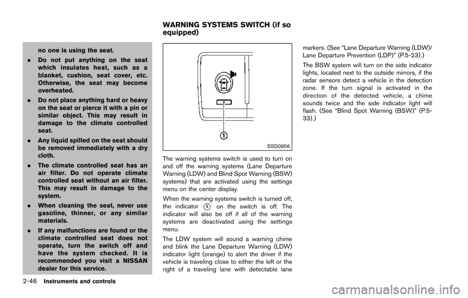
The warning systems switch is used to turn on
and off the warning systems (Lane Departure
Warning (LDW) and Blind Spot Warning (BSW)
systems) that are activated using the settings
menu on the center display.
When the warning systems switch is turned off,
the indicator
*1on the switch is off. The
indicator will also be off if all of the warning
systems are deactivated using the settings
menu.
The LDW system will sound a warning chime
and blink the Lane Departure Warning (LDW)
indicator light (orange) to alert the driver if the
vehicle is traveling close to either the left or the
right of a traveling lane with detectable lane markers. (See “Lane Departure Warning (LDW)/
Lane Departure Prevention (LDP)” (P.5-23).)
The BSW system will turn on the side indicator
lights, located next to the outside mirrors, if the
radar sensors detect a vehicle in the detection
zone. If the turn signal is activated in the
direction of the detected vehicle, a chime
sounds twice and the side indicator light will
flash. (See “Blind Spot Warning (BSW)” (P.5-
33) .)
WARNING SYSTEMS SWITCH (if so
equipped)
Page 198 of 614
4 Monitor, heater, air conditioner, audio, phoneand voice recognition systems
Safety note ........................................................................\
.......... 4-3
Center multi-function control panel ...................................... 4-4
How to use multi-function controller .............................. 4-5
How to use touch screen ................................................. 4-5
Menu options ........................................................................\
4-7
How to select menus on the screen .............................. 4-8
Vehicle information and settings ........................................... 4-8 How to use STATUS button ............................................. 4-8
How to use brightness control and display
ON/OFF button ................................................................... 4-8
How to use CAMERA button (if so equipped) ........... 4-8
How to use DISP button (if so equipped) ................... 4-8
How to use INFO button .................................................. 4-9
How to use SETTING button ....................................... 4-13
RearView Monitor (if so equipped) ................................... 4-21 RearView Monitor system operation ........................... 4-22
How to read the displayed lines .................................. 4-22
How to park with predictive course lines .................. 4-23
Adjusting the screen ....................................................... 4-25
Predictive course line settings ...................................... 4-26
RearView Monitor system limitations .......................... 4-26
Sonar settings ................................................................... 4-27
Sonar indicator .................................................................. 4-27
System maintenance ....................................................... 4-28 Around View�ŠMonitor (if so equipped) .......................... 4-29
Around View�ŠMonitor system operation ................. 4-30
How to adjust the screen view ................................... 4-37
Around View
�ŠMonitor settings .................................. 4-38
Around View�ŠMonitor system limitations ................ 4-38
System maintenance ..................................................... 4-41
Camera aiding sonar function (models with Around
View
�ŠMonitor) ....................................................................... 4-42
Sonar system operation ............................................... 4-43
Turning on and off the sonar function ...................... 4-43
Sonar system limitations .............................................. 4-45
System temporarily unavailable .................................. 4-45
System maintenance ..................................................... 4-45
Moving Object Detection (MOD) ..................................... 4-46 MOD system operation ................................................ 4-47
Turning on and off the MOD system ........................ 4-48
MOD system limitations ............................................... 4-49
System maintenance ..................................................... 4-50
Ventilators ........................................................................\
........ 4-51
Center ventilators ........................................................... 4-51
Side ventilators ............................................................... 4-51
Rear ventilators ............................................................... 4-52
Heater and air conditioner .................................................. 4-52
Automatic air conditioner ............................................. 4-54
Operating tips ................................................................. 4-58
Page 201 of 614
4-4Monitor, heater, air conditioner, audio, phone and voice recognition systems
SAA3020Type A (if so equipped)
SAA3021Type B (if so equipped)
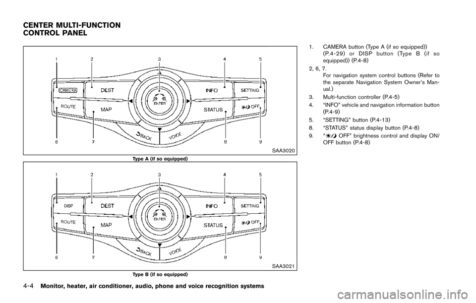
1. CAMERA button (Type A (if so equipped))(P.4-29) or DISP button (Type B (if so
equipped)) (P.4-8)
2, 6, 7. For navigation system control buttons (Refer to
the separate Navigation System Owner’s Man-
ual.)
3. Multi-function controller (P.4-5)
4. “INFO” vehicle and navigation information button (P.4-9)
5. “SETTING” button (P.4-13)
8. “STATUS” status display button (P.4-8)
9. “
OFF” brightness control and display ON/
OFF button (P.4-8)
CENTER MULTI-FUNCTION
CONTROL PANEL
Page 202 of 614
SAA3025
HOW TO USE MULTI-FUNCTION
CONTROLLER
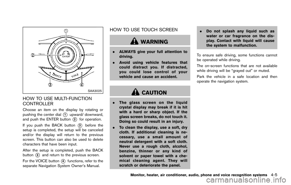
Choose an item on the display by rotating or
pushing the center dial
*1upward/ downward,
and push the ENTER button
*2for operation.
If you push the BACK button
*3before the
setup is completed, the setup will be canceled
and/or the display will return to the previous
screen. This button can also be used to delete
characters that have been input.
After the setup is completed, push the BACK
button
*3and return to the previous screen.
For the VOICE button
*4functions, refer to the
separate Navigation System Owner’s Manual.
HOW TO USE TOUCH SCREEN
WARNING
. ALWAYS give your full attention to
driving.
. Avoid using vehicle features that
could distract you. If distracted,
you could lose control of your
vehicle and cause an accident.
CAUTION
.The glass screen on the liquid
crystal display may break if it is hit
with a hard or sharp object. If the
glass screen breaks, do not touch it.
Doing so could result in an injury.
. To clean the display, use a soft, dry
cloth. If additional cleaning is ne-
cessary, use a small amount of
neutral detergent with a soft cloth.
Never use a rough cloth, alcohol,
benzine, thinner or any kind of
solvent or paper towel with a che-
mical cleaning agent. They will
scratch or deteriorate the panel. .
Do not splash any liquid such as
water or car fragrance on the dis-
play. Contact with liquid will cause
the system to malfunction.
To ensure safe driving, some functions cannot
be operated while driving.
The on-screen functions that are not available
while driving will be “grayed out” or muted.
Park the vehicle in a safe location and then
operate the navigation system.
Monitor, heater, air conditioner, audio, phone and voice recognition systems4-5