2017 NISSAN ARMADA rear view mirror
[x] Cancel search: rear view mirrorPage 10 of 614
JVC0953X
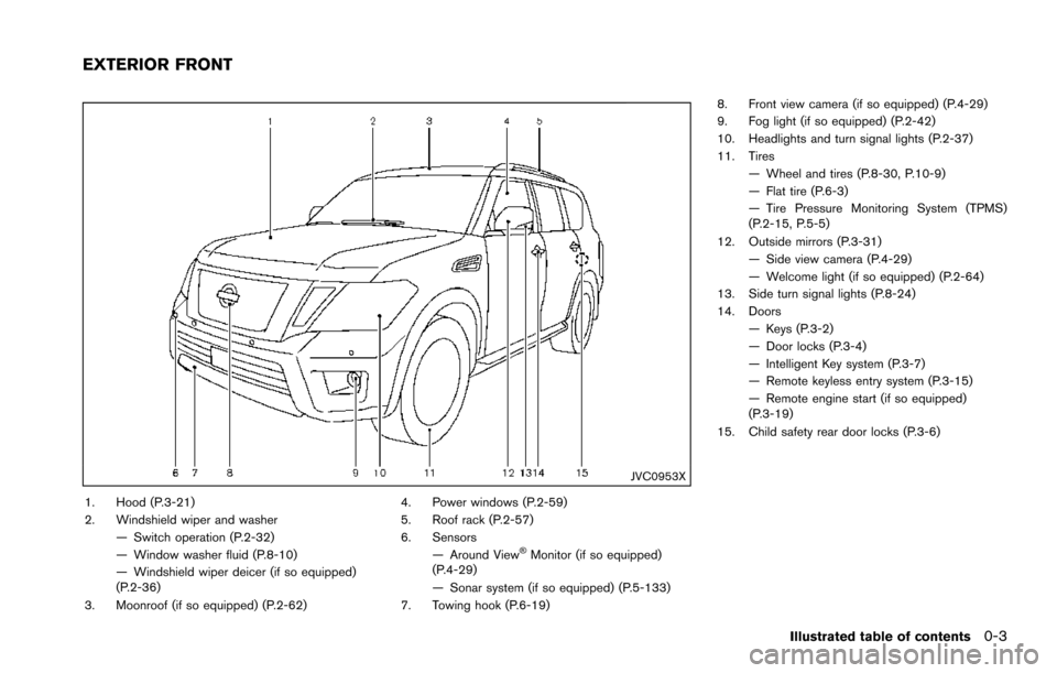
1. Hood (P.3-21)
2. Windshield wiper and washer— Switch operation (P.2-32)
— Window washer fluid (P.8-10)
— Windshield wiper deicer (if so equipped)
(P.2-36)
3. Moonroof (if so equipped) (P.2-62) 4. Power windows (P.2-59)
5. Roof rack (P.2-57)
6. Sensors
— Around View
�ŠMonitor (if so equipped)
(P.4-29)
— Sonar system (if so equipped) (P.5-133)
7. Towing hook (P.6-19) 8. Front view camera (if so equipped) (P.4-29)
9. Fog light (if so equipped) (P.2-42)
10. Headlights and turn signal lights (P.2-37)
11. Tires
— Wheel and tires (P.8-30, P.10-9)
— Flat tire (P.6-3)
— Tire Pressure Monitoring System (TPMS)
(P.2-15, P.5-5)
12. Outside mirrors (P.3-31) — Side view camera (P.4-29)
— Welcome light (if so equipped) (P.2-64)
13. Side turn signal lights (P.8-24)
14. Doors
— Keys (P.3-2)
— Door locks (P.3-4)
— Intelligent Key system (P.3-7)
— Remote keyless entry system (P.3-15)
— Remote engine start (if so equipped)
(P.3-19)
15. Child safety rear door locks (P.3-6)
Illustrated table of contents0-3
EXTERIOR FRONT
Page 12 of 614
JVC0955X
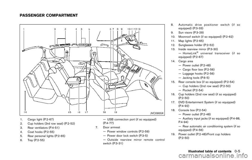
1. Cargo light (P.2-67)
2. Cup holders (3rd row seat) (P.2-52)
3. Rear ventilators (P.4-51)
4. Coat hooks (P.2-55)
5. Rear personal lights (P.2-65)
6. Tray (P.2-55)— USB connection port (if so equipped)
(P.4-77)
7. Door armrest — Power window controls (P.2-59)
— Power door lock switch (P.3-5)
— Outside rearview mirror remote control
switch (P.3-31) 8. Automatic drive positioner switch (if so
equipped) (P.3-33)
9. Sun visors (P.3-29)
10. Moonroof switch (if so equipped) (P.2-62)
11. Map lights (P.2-65)
12. Sunglasses holder (P.2-52)
13. Inside rearview mirror (P.3-30) — HomeLink
�Šuniversal transceiver (if so
equipped) (P.2-67)
14. Cargo area — Power outlet (P.2-48)
— Cargo floor box (P.2-56)
— Luggage hooks (P.2-56)
— Jacking tools (P.6-5)
15. Rear console box (if so equipped) (P.2-54) — Cup holders (2nd row seat) (P.2-50)
— Pocket (P.2-54)
16. Cup holders (2nd row seat) (if so equipped) (P.2-50)
17. DVD Entertainment System (if so equipped) (P.4-92)
18. Console box (P.2-54) — Power outlet (P.2-48)
— Auxiliary input jacks (if so equipped) (P.4-88,
P.4-94)
— Rear automatic air conditioning system (if so
equipped) (P.4-56)
19. Power outlet (P.2-48)/Front cup holders (P.2-50)
Illustrated table of contents0-5
PASSENGER COMPARTMENT
Page 128 of 614
Battery saver system
A chime will sound when the driver side door is
opened with the light switch in theorposition and the ignition switch in the OFF or
LOCK position.
When the headlight switch is in the
orposition while the ignition switch is in the ON
position, the lights will automatically turn off after
a period of time when the ignition switch has
been pushed to the OFF position.
When the headlight switch remains in the
orposition after the lights automatically turn
off, the lights will turn on when the ignition
switch is pushed to the ON position.
CAUTION
. When you turn on the headlight
switch again after the lights auto-
matically turn off, the lights will not
turn off automatically. Be sure to
turn the light switch to the OFF
position when you leave the vehicle
for extended periods of time, other-
wise the battery will be discharged.
. Never leave the light switch on
when the engine is not running for
extended periods of time even if the headlights turn off automatically.
SIC2275
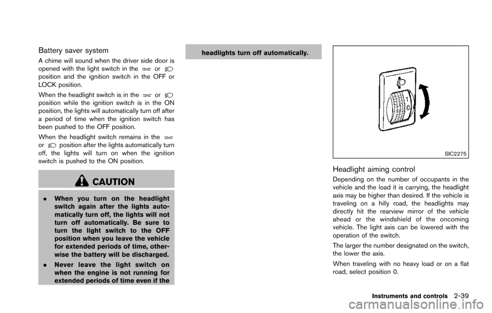
Headlight aiming control
Depending on the number of occupants in the
vehicle and the load it is carrying, the headlight
axis may be higher than desired. If the vehicle is
traveling on a hilly road, the headlights may
directly hit the rearview mirror of the vehicle
ahead or the windshield of the oncoming
vehicle. The light axis can be lowered with the
operation of the switch.
The larger the number designated on the switch,
the lower the axis.
When traveling with no heavy load or on a flat
road, select position 0.
Instruments and controls2-39
Page 191 of 614
3-30Pre-driving checks and adjustments
CAUTION
.Do not store the main sun visor
before storing the extension sun
visor.
. Do not pull the extension sun visor
forcedly downward.
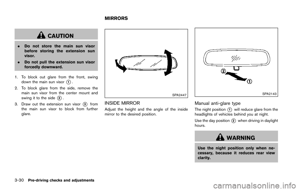
1. To block out glare from the front, swing down the main sun visor
*1.
2. To block glare from the side, remove the main sun visor from the center mount and
swing it to the side
*2.
3. Draw out the extension sun visor
*3from
the main sun visor to block from further
glare.
SPA2447
INSIDE MIRROR
Adjust the height and the angle of the inside
mirror to the desired position.
SPA2143
Manual anti-glare type
The night position*1will reduce glare from the
headlights of vehicles behind you at night.
Use the day position
*2when driving in daylight
hours.
WARNING
Use the night position only when ne-
cessary, because it reduces rear view
clarity.
MIRRORS
Page 192 of 614
SPA2450-A
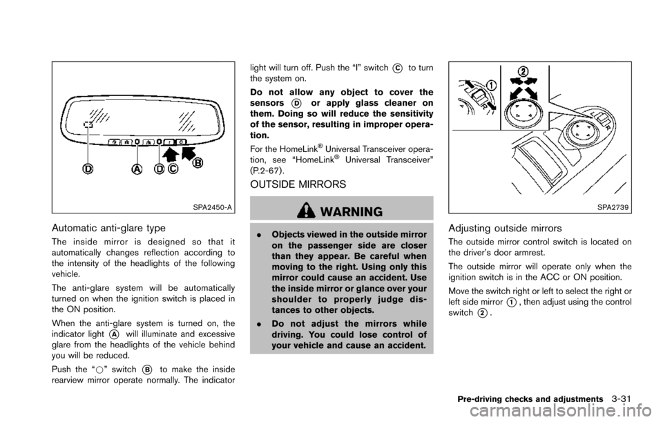
Automatic anti-glare type
The inside mirror is designed so that it
automatically changes reflection according to
the intensity of the headlights of the following
vehicle.
The anti-glare system will be automatically
turned on when the ignition switch is placed in
the ON position.
When the anti-glare system is turned on, the
indicator light
*Awill illuminate and excessive
glare from the headlights of the vehicle behind
you will be reduced.
Push the “*” switch
*Bto make the inside
rearview mirror operate normally. The indicator light will turn off. Push the “I” switch
*Cto turn
the system on.
Do not allow any object to cover the
sensors
*Dor apply glass cleaner on
them. Doing so will reduce the sensitivity
of the sensor, resulting in improper opera-
tion.
For the HomeLink
�ŠUniversal Transceiver opera-
tion, see “HomeLink�ŠUniversal Transceiver”
(P.2-67) .
OUTSIDE MIRRORS
WARNING
. Objects viewed in the outside mirror
on the passenger side are closer
than they appear. Be careful when
moving to the right. Using only this
mirror could cause an accident. Use
the inside mirror or glance over your
shoulder to properly judge dis-
tances to other objects.
. Do not adjust the mirrors while
driving. You could lose control of
your vehicle and cause an accident.
SPA2739
Adjusting outside mirrors
The outside mirror control switch is located on
the driver’s door armrest.
The outside mirror will operate only when the
ignition switch is in the ACC or ON position.
Move the switch right or left to select the right or
left side mirror
*1, then adjust using the control
switch
*2.
Pre-driving checks and adjustments3-31
Page 194 of 614
4. The outside mirror surfaces move down-ward.
When one of the following conditions has
occurred, the outside mirror surfaces will return
to their original positions.
. The shift lever is moved to any position other
than R (Reverse) .
. The outside mirror control switch is set to
the center position.
. The ignition switch is placed in the OFF
position.
Automatic anti-glare (if so equipped)
The outside rearview mirrors are designed so
that its automatically change reflection accord-
ing to the intensity of the headlights of the
vehicle following you.
The anti-glare system will be automatically
turned on when the ignition switch is placed in
the ON position.SIC4448
VANITY MIRROR
To use the front vanity mirror, pull down the sun
visor and pull up the cover.
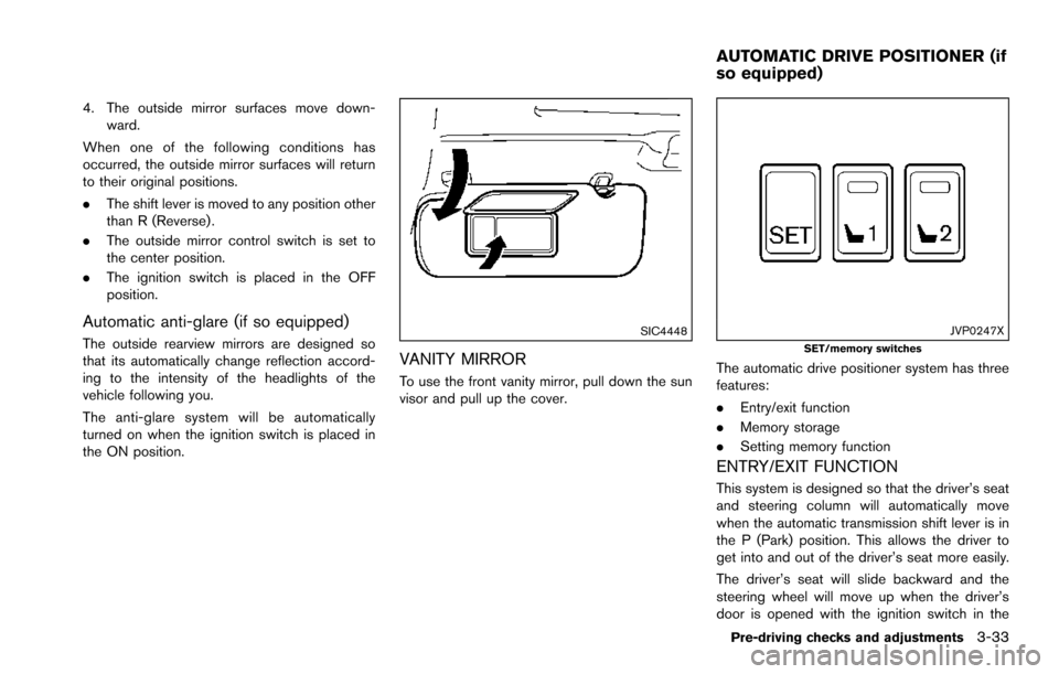
JVP0247XSET/memory switches
The automatic drive positioner system has three
features:
.Entry/exit function
. Memory storage
. Setting memory function
ENTRY/EXIT FUNCTION
This system is designed so that the driver’s seat
and steering column will automatically move
when the automatic transmission shift lever is in
the P (Park) position. This allows the driver to
get into and out of the driver’s seat more easily.
The driver’s seat will slide backward and the
steering wheel will move up when the driver’s
door is opened with the ignition switch in the
Pre-driving checks and adjustments3-33
AUTOMATIC DRIVE POSITIONER (if
so equipped)
Page 218 of 614
.(Previous)
Select the “
” key to display the previous
file.
Setting the Image Viewer:
The Image Viewer setting display will appear
when selecting the “Settings” key on the full
screen display. The following settings are
available for the full screen display.
. Slideshow Speed
Select the “Slideshow Speed” key. From the
following display, select the changing time
from 5, 10, 30, 60 seconds or “No Auto
Change”.
. Slideshow Order
Select the “Slideshow Order” key. From the
following display, select “Random” or “Order
List”. For “Order List”, the image order is the
order of the files as stored on the USB
memory.
Operating tips:
. Only files that meet the following conditions
will be displayed.
— Image type: JPEG
— File Extensions: *.jpg, *jpeg
— Maximum Resolution: 2048 61536
pixels — Maximum Size: 2 MB
— Colors: 32768 (15 bit)
— Maximum File Name lengths: 253 Bytes
— Maximum Folders: 500
— Maximum Images per Folder: 1024
. If an electronic device (such as a digital
camera) is directly connected to the vehicle
using a USB cable, no image will be
displayed on the screen.
. If the file name is too long, some file names
may not be entirely displayed.
. When the total number of characters in the
file name exceeds 100 or if 1 file name in a
directory exceeds 100 characters, all files
will show a shortened 8-character version.
The image will still be displayed when
selected.WARNING
Failure to follow the warnings and
instructions for proper use of the Rear-
View Monitor system could result in
serious injury or death.
.The RearView Monitor is a conve-
nience but it is not a substitute for
proper backing. Always turn and
look out the windows, and check
mirrors to be sure that it is safe to
move before operating the vehicle.
Always back up slowly.
. The system is designed as an aid to
the driver in showing large station-
ary objects directly behind the vehi-
cle, to help avoid damaging the
vehicle.
. The distance guide line and the
vehicle width line should be used
as a reference only when the vehicle
is on a level paved surface. The
distance viewed on the monitor is
for reference only and may be
different than the actual distance
between the vehicle and displayed
objects.
Monitor, heater, air conditioner, audio, phone and voice recognition systems4-21
REARVIEW MONITOR (if so
equipped)
Page 223 of 614
4-26Monitor, heater, air conditioner, audio, phone and voice recognition systems
SAA2404
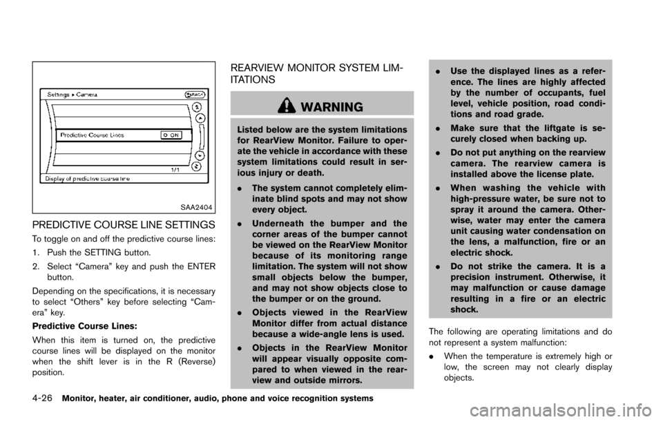
PREDICTIVE COURSE LINE SETTINGS
To toggle on and off the predictive course lines:
1. Push the SETTING button.
2. Select “Camera” key and push the ENTERbutton.
Depending on the specifications, it is necessary
to select “Others” key before selecting “Cam-
era” key.
Predictive Course Lines:
When this item is turned on, the predictive
course lines will be displayed on the monitor
when the shift lever is in the R (Reverse)
position.
REARVIEW MONITOR SYSTEM LIM-
ITATIONS
WARNING
Listed below are the system limitations
for RearView Monitor. Failure to oper-
ate the vehicle in accordance with these
system limitations could result in ser-
ious injury or death.
. The system cannot completely elim-
inate blind spots and may not show
every object.
. Underneath the bumper and the
corner areas of the bumper cannot
be viewed on the RearView Monitor
because of its monitoring range
limitation. The system will not show
small objects below the bumper,
and may not show objects close to
the bumper or on the ground.
. Objects viewed in the RearView
Monitor differ from actual distance
because a wide-angle lens is used.
. Objects in the RearView Monitor
will appear visually opposite com-
pared to when viewed in the rear-
view and outside mirrors. .
Use the displayed lines as a refer-
ence. The lines are highly affected
by the number of occupants, fuel
level, vehicle position, road condi-
tions and road grade.
. Make sure that the liftgate is se-
curely closed when backing up.
. Do not put anything on the rearview
camera. The rearview camera is
installed above the license plate.
. When washing the vehicle with
high-pressure water, be sure not to
spray it around the camera. Other-
wise, water may enter the camera
unit causing water condensation on
the lens, a malfunction, fire or an
electric shock.
. Do not strike the camera. It is a
precision instrument. Otherwise, it
may malfunction or cause damage
resulting in a fire or an electric
shock.
The following are operating limitations and do
not represent a system malfunction:
. When the temperature is extremely high or
low, the screen may not clearly display
objects.