2017 NISSAN ARMADA stop start
[x] Cancel search: stop startPage 360 of 614
.Do not downshift abruptly on slip-
pery roads. This may cause a loss of
control.
CAUTION
.Except in an emergency, do not shift
to the N (Neutral) position while
driving. Coasting with the transmis-
sion in the N (Neutral) position may
cause serious damage to the trans-
mission.
. To avoid possible damage to your
vehicle; when stopping the vehicle
on an uphill grade, do not hold the
vehicle by depressing the accelera-
tor pedal. The foot brake should be
used for this purpose.
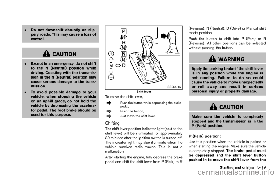
SSD0945Shift lever
To move the shift lever,
: Push the button while depressing the brake
pedal,
: Push the button,
: Just move the shift lever.
Shifting
The shift lever position indicator light (next to the
shift lever) will be illuminated for approximately
30 minutes after the ignition switch is turned off.
The indicator light may also illuminate when the
vehicle receives radio waves. This is not a
malfunction.
After starting the engine, fully depress the brake
pedal and shift the shift lever from P (Park) to R (Reverse) , N (Neutral) , D (Drive) or Manual shift
mode position.
Push the button to shift into P (Park) or R
(Reverse) . All other positions can be selected
without pushing the button.
WARNING
Apply the parking brake if the shift lever
is in any position while the engine is
not running. Failure to do so could
cause the vehicle to move unexpectedly
or roll away and result in serious
personal injury or property damage.
CAUTION
Make sure the vehicle is completely
stopped and the transmission is in the
P (Park) position.
P (Park) position:
Use this position when the vehicle is parked or
when starting the engine. Make sure the vehicle
is completely stopped. The brake pedal must
be depressed and the shift lever button
pushed in to move the shift lever from the
Starting and driving5-19
Page 361 of 614
5-20Starting and driving
N (Neutral) position or any drive position to
the P (Park) position.Apply the parking brake.
When parking on a hill, apply the parking brake
first, then move the shift lever to the P (Park)
position.
CAUTION
Use this position only when the vehicle
is completely stopped.
R (Reverse):
Use this position to back up. Always be sure the
vehicle is completely stopped before selecting
the R (Reverse) position. The brake pedal
must be depressed and the shift lever
button pushed in to move the shift lever
from the P (Park) position, the N (Neutral)
position or any drive position to the R
(Reverse) position.
N (Neutral):
Neither forward nor reverse gear is engaged.
The engine can be started in this position. You
may shift to the N (Neutral) position and restart a
stalled engine while the vehicle is moving.
D (Drive):
Use this position for all normal forward driving.
Manual shift mode
When the shift lever is in the manual shift gate,
the transmission is ready for the manual shift
mode. Shift ranges can be selected manually by
moving the shift lever up or down.
When shifting up, move the shift lever to the +
(up) side. The transmission shifts to the higher
range.
When shifting down, move the shift lever to the
�í (down) side. The transmission shifts to the
lower range.
When canceling the manual shift mode, return
the shift lever to the D (Drive) position. The
transmission returns to the normal driving mode.
In the manual shift mode, the shift range is
displayed on the position indicator in the meter. Shift ranges up or down one by one as follows:M1
?
/M2?
/M3?
/M4?
/M5?
/M6?
/M7
M7 (7th):
Use this position for all normal forward driving at
highway speeds.
M6 (6th) andM5 (5th):
Use these positions when driving up long
slopes, or for engine braking when driving down
long slopes.
M4 (4th) ,M3 (3rd) andM2 (2nd):
Use these positions for hill climbing or engine
braking on downhill grades.
M1 (1st):
Use this position when climbing steep hills
slowly or driving slowly through deep snow, or
for maximum engine braking on steep downhill
grades.
. Remember not to drive at high speeds for
extended periods of time in lower than 7th
gear. This reduces fuel economy.
. Moving the shift lever rapidly to the same
side twice will shift the ranges in succes-
sion.
. In the manual shift mode, the transmis-
sion may not shift to the selected gear
or may automatically shift to the other
Page 362 of 614
gear. This helps maintain driving per-
formance and reduces the chance of
vehicle damage or loss of control.
. When the transmission does not shift
to the selected gear, the Automatic
Transmission (AT) position indicator
light (in the vehicle information dis-
play) will blink and the buzzer will
sound.
. In the manual shift mode, the transmis-
sion automatically shifts down to 1st
gear before the vehicle comes to a
stop. When accelerating again, it is
necessary to shift up to the desired
range.
Accelerator downshift — In D (Drive)
position —
For passing or hill climbing, fully depress the
accelerator pedal to the floor. This shifts the
transmission down into the lower gear, depend-
ing on the vehicle speed.
Fail-safe
When the fail-safe operation occurs, note that
the transmission will be locked in any of the
forward gears according to the condition.
If the vehicle is driven under extreme
conditions, such as excessive wheel spin-
ning and subsequent hard braking, the fail-safe system may be activated. This will
occur even if all electrical circuits are
functioning properly. In this case, push
the switch to the OFF position and wait for
3 seconds. Then push the ignition switch
back to the ON position. The vehicle
should return to its normal operating
condition. If it does not return to its normal
operating condition, have the transmission
checked and repaired, if necessary. It is
recommended you visit a NISSAN dealer
for this service.
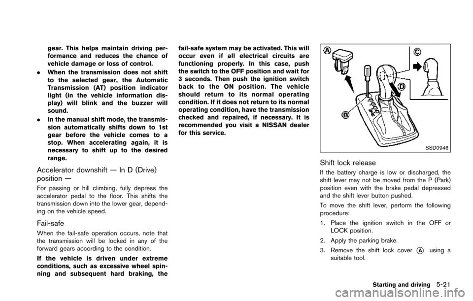
SSD0946
Shift lock release
If the battery charge is low or discharged, the
shift lever may not be moved from the P (Park)
position even with the brake pedal depressed
and the shift lever button pushed.
To move the shift lever, perform the following
procedure:
1. Place the ignition switch in the OFF or
LOCK position.
2. Apply the parking brake.
3. Remove the shift lock cover
*Ausing a
suitable tool.
Starting and driving5-21
Page 368 of 614
NOTE:
.The LDP system is not designed to
work when you operate the lane
change signal and change traveling
lanes in the direction of the signal.
(The LDP system will become operable
again approximately 2 seconds after
the lane change signal is turned off.)
. The LDP braking assist will not operate
or will stop operating and only a
warning chime will sound under the
following conditions.
—When the brake pedal is depressed.
— When the steering wheel is turned
as far as necessary for the vehicle to
change lanes.
— When the accelerator pedal is de-
pressed while brake control assist is
provided.
— When the ICC, DCA, BSI, BSW,
PFCW or FEB warnings sound.
— When the hazard warning flashers
are operated.
— When driving on a curve at a high
speed.
. While the LDP system is operating, you
may hear a sound of brake operation.
This is normal and indicates that the
LDP system is operating properly.
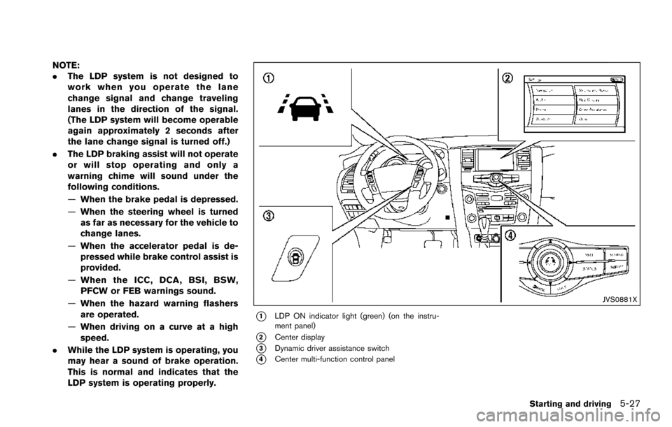
JVS0881X
*1LDP ON indicator light (green) (on the instru-
ment panel)
*2Center display
*3Dynamic driver assistance switch
*4Center multi-function control panel
Starting and driving5-27
Page 373 of 614
5-32Starting and driving
LDP system:If the vehicle is parked in direct
sunlight under high temperature conditions (over
approximately 1048F (408C)) and then the LDP
system is turned on, the LDP system will be
turned off automatically, a beep will sound and
the LDP ON indicator light (green)
*1will blink.
The LDW and LDP systems are not available
until the conditions no longer exist.
Action to take:
When the above conditions no longer exist, the
LDW system will resume automatically.
For the LDP system, push the dynamic driver
assistance switch
*3again to turn the LDP
system back on.
SYSTEM MALFUNCTION
LDW system: When the LDW system malfunc-
tions, it will cancel automatically, and the LDW
indicator light (orange) will illuminate.
LDP system: When the LDP system malfunc-
tions, it will be turned off automatically, a beep
will sound, and the LDW indicator light (orange)
will illuminate.
Action to take:
Stop the vehicle in a safe location, place the
vehicle in the P (Park) position, turn the engine
off and restart the engine. If the LDW indicator
light (orange) continues to illuminate, have the
system checked. It is recommended you visit a NISSAN dealer for this service.
SSD0453
SYSTEM MAINTENANCE
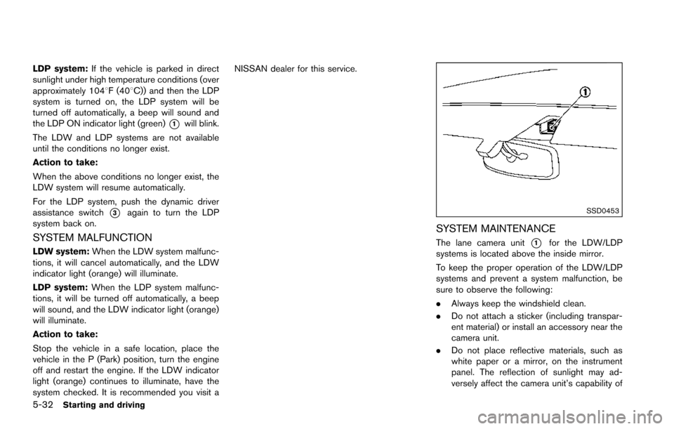
The lane camera unit*1for the LDW/LDP
systems is located above the inside mirror.
To keep the proper operation of the LDW/LDP
systems and prevent a system malfunction, be
sure to observe the following:
. Always keep the windshield clean.
. Do not attach a sticker (including transpar-
ent material) or install an accessory near the
camera unit.
. Do not place reflective materials, such as
white paper or a mirror, on the instrument
panel. The reflection of sunlight may ad-
versely affect the camera unit’s capability of
Page 378 of 614
JVS0473X
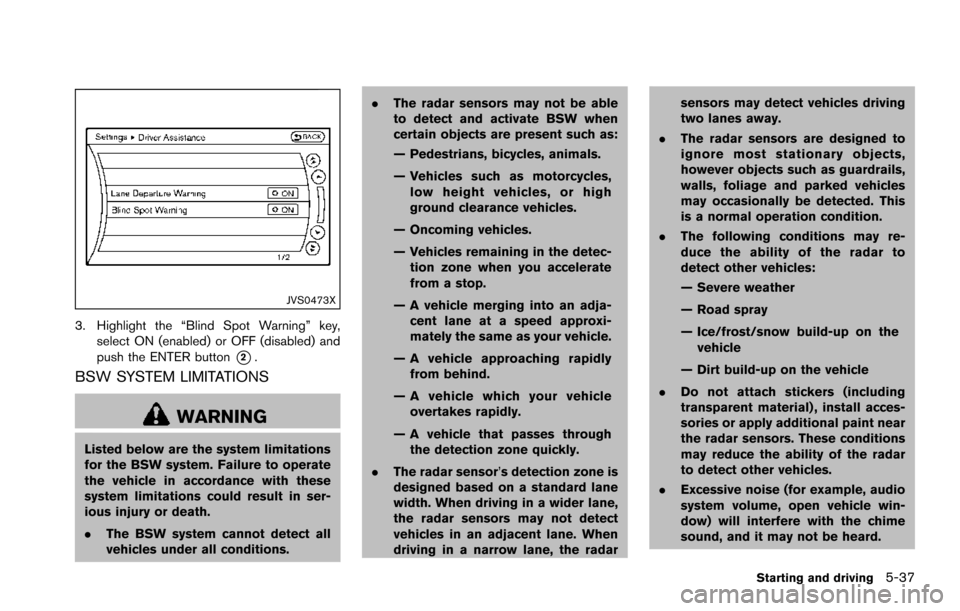
3. Highlight the “Blind Spot Warning” key,select ON (enabled) or OFF (disabled) and
push the ENTER button
*2.
BSW SYSTEM LIMITATIONS
WARNING
Listed below are the system limitations
for the BSW system. Failure to operate
the vehicle in accordance with these
system limitations could result in ser-
ious injury or death.
.The BSW system cannot detect all
vehicles under all conditions. .
The radar sensors may not be able
to detect and activate BSW when
certain objects are present such as:
— Pedestrians, bicycles, animals.
— Vehicles such as motorcycles,
low height vehicles, or high
ground clearance vehicles.
— Oncoming vehicles.
— Vehicles remaining in the detec- tion zone when you accelerate
from a stop.
— A vehicle merging into an adja- cent lane at a speed approxi-
mately the same as your vehicle.
— A vehicle approaching rapidly from behind.
— A vehicle which your vehicle overtakes rapidly.
— A vehicle that passes through the detection zone quickly.
. The radar sensor’s detection zone is
designed based on a standard lane
width. When driving in a wider lane,
the radar sensors may not detect
vehicles in an adjacent lane. When
driving in a narrow lane, the radar sensors may detect vehicles driving
two lanes away.
. The radar sensors are designed to
ignore most stationary objects,
however objects such as guardrails,
walls, foliage and parked vehicles
may occasionally be detected. This
is a normal operation condition.
. The following conditions may re-
duce the ability of the radar to
detect other vehicles:
— Severe weather
— Road spray
— Ice/frost/snow build-up on the
vehicle
— Dirt build-up on the vehicle
. Do not attach stickers (including
transparent material) , install acces-
sories or apply additional paint near
the radar sensors. These conditions
may reduce the ability of the radar
to detect other vehicles.
. Excessive noise (for example, audio
system volume, open vehicle win-
dow) will interfere with the chime
sound, and it may not be heard.
Starting and driving5-37
Page 383 of 614
5-42Starting and driving
Action to take:
Stop the vehicle in a safe location, place the
vehicle in the P (Park) position, turn the engine
off and restart the engine.
If the BSW system warning light continues to
illuminate, have the system checked. It is
recommended you visit a NISSAN dealer for
this service.
JVS0908X
SYSTEM MAINTENANCE
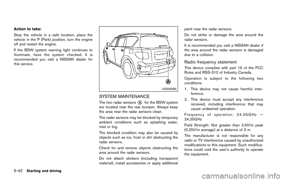
The two radar sensors*Afor the BSW system
are located near the rear bumper. Always keep
the area near the radar sensors clean.
The radar sensors may be blocked by temporary
ambient conditions such as splashing water,
mist or fog.
The blocked condition may also be caused by
objects such as ice, frost or dirt obstructing the
radar sensors.
Check for and remove objects obstructing the
area around the radar sensors.
Do not attach stickers (including transparent
material) , install accessories or apply additional paint near the radar sensors.
Do not strike or damage the area around the
radar sensors.
It is recommended you visit a NISSAN dealer if
the area around the radar sensors is damaged
due to a collision.
Radio frequency statement
This device complies with part 15 of the FCC
Rules and RSS-310 of Industry Canada.
Operation is subject to the following two
conditions:
1. This device may not cause harmful inter-
ference.
2. This device must accept any interference received, including interference that may
cause undesired operation.
Frequency of operation: 24.05GHz —
24.25GHz
Field Strength: Not greater than 2.5V/m peak
(0.25V/m average) at a distance of 3 m
The manufacturer is not responsible for any
radio or TV interference caused by unauthorized
modifications to this equipment. Such modifica-
tions could void the user’s authority to operate
the equipment.
Page 389 of 614
5-48Starting and driving
.The radar sensors may not be able
to detect and activate BSI when
certain objects are present such as:
— Pedestrians, bicycles, animals.
— Vehicles such as motorcycles,
low height vehicles, or high
ground clearance vehicles.
— Vehicles remaining in the detec- tion zone when you accelerate
from a stop.
— Oncoming vehicles.
— A vehicle merging into an adja- cent lane at a speed approxi-
mately the same as your vehicle.
— A vehicle approaching rapidly from behind.
— A vehicle which your vehicle overtakes rapidly.
— A vehicle that passes through the detection zone quickly.
. The radar sensor’s detection zone is
designed based on a standard lane
width. When driving in a wider lane,
the radar sensors may not detect
vehicles in an adjacent lane. When
driving in a narrow lane, the radar sensors may detect vehicles driving
two lanes away.
. The radar sensors are designed to
ignore most stationary objects,
however objects such as guardrails,
walls, foliage and parked vehicles
may occasionally be detected. This
is a normal operation condition.
. The camera may not detect lane
markers in the following situations
and the BSI system may not operate
properly.
— On roads where there are multi-
ple parallel lane markers; lane
markers that are faded or not
painted clearly; yellow painted
lane markers; non-standard lane
markers; lane markers covered
with water, dirt, snow, etc.
— On roads where discontinued lane markers are still detect-
able.
— On roads where there are sharp curves.
— On roads where there are shar- ply contrasting objects, such as
shadows, snow, water, wheel
ruts, seams or lines remaining after road repairs.
— On roads where the traveling lane merges or separates.
— When the vehicle’s traveling di- rection does not align with the
lane markers.
— When traveling close to the vehicle in front of you, which
obstructs the lane camera unit
detection range.
— When rain, snow or dirt adheres to the windshield in front of a
lane camera unit.
— When the headlights are not bright due to dirt on the lens or
if aiming is not adjusted prop-
erly.
— When strong light enters a lane camera unit. (For example: light
directly shines on the front of
the vehicle at sunrise or sunset.)
— When a sudden change in brightness occurs. (For example:
when the vehicle enters or exits
a tunnel or under a bridge.)