2017 NISSAN ARMADA display
[x] Cancel search: displayPage 15 of 614
0-8Illustrated table of contents
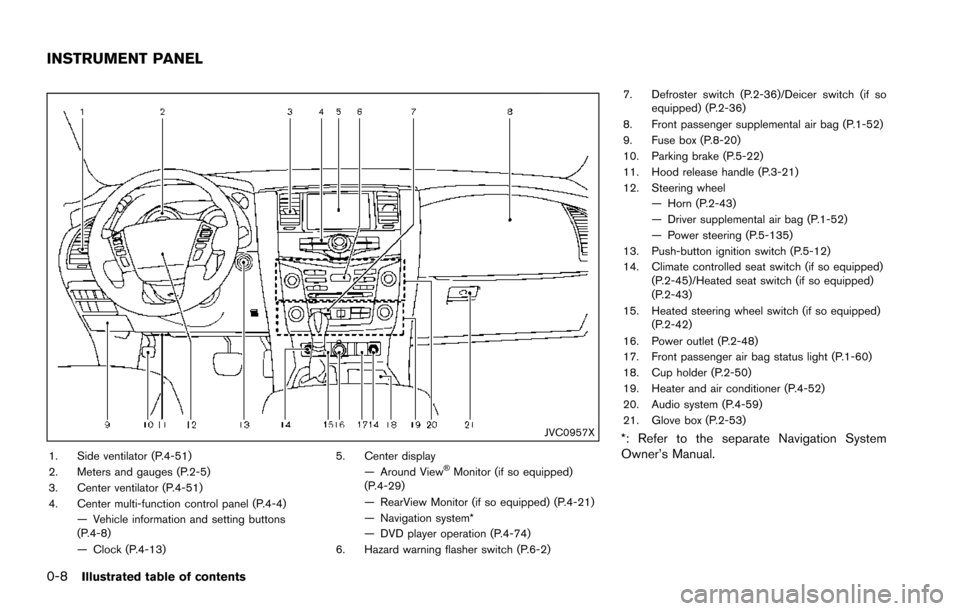
JVC0957X
1. Side ventilator (P.4-51)
2. Meters and gauges (P.2-5)
3. Center ventilator (P.4-51)
4. Center multi-function control panel (P.4-4)— Vehicle information and setting buttons
(P.4-8)
— Clock (P.4-13) 5. Center display
— Around View�ŠMonitor (if so equipped)
(P.4-29)
— RearView Monitor (if so equipped) (P.4-21)
— Navigation system*
— DVD player operation (P.4-74)
6. Hazard warning flasher switch (P.6-2) 7. Defroster switch (P.2-36)/Deicer switch (if so
equipped) (P.2-36)
8. Front passenger supplemental air bag (P.1-52)
9. Fuse box (P.8-20)
10. Parking brake (P.5-22)
11. Hood release handle (P.3-21)
12. Steering wheel — Horn (P.2-43)
— Driver supplemental air bag (P.1-52)
— Power steering (P.5-135)
13. Push-button ignition switch (P.5-12)
14. Climate controlled seat switch (if so equipped) (P.2-45)/Heated seat switch (if so equipped)
(P.2-43)
15. Heated steering wheel switch (if so equipped) (P.2-42)
16. Power outlet (P.2-48)
17. Front passenger air bag status light (P.1-60)
18. Cup holder (P.2-50)
19. Heater and air conditioner (P.4-52)
20. Audio system (P.4-59)
21. Glove box (P.2-53)
*: Refer to the separate Navigation System
Owner’s Manual.
INSTRUMENT PANEL
Page 16 of 614
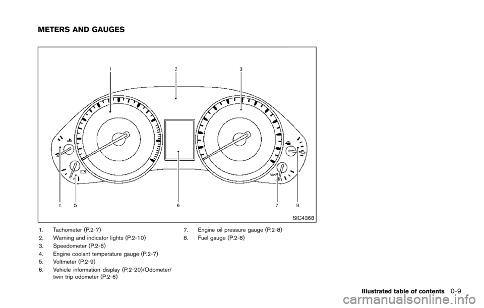
SIC4368
1. Tachometer (P.2-7)
2. Warning and indicator lights (P.2-10)
3. Speedometer (P.2-6)
4. Engine coolant temperature gauge (P.2-7)
5. Voltmeter (P.2-9)
6. Vehicle information display (P.2-20)/Odometer/twin trip odometer (P.2-6) 7. Engine oil pressure gauge (P.2-8)
8. Fuel gauge (P.2-8)
Illustrated table of contents0-9
METERS AND GAUGES
Page 34 of 614
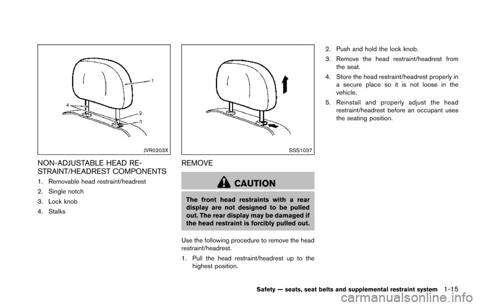
JVR0203X
NON-ADJUSTABLE HEAD RE-
STRAINT/HEADREST COMPONENTS
1. Removable head restraint/headrest
2. Single notch
3. Lock knob
4. Stalks
SSS1037
REMOVE
CAUTION
The front head restraints with a rear
display are not designed to be pulled
out. The rear display may be damaged if
the head restraint is forcibly pulled out.
Use the following procedure to remove the head
restraint/headrest.
1. Pull the head restraint/headrest up to the highest position. 2. Push and hold the lock knob.
3. Remove the head restraint/headrest from
the seat.
4. Store the head restraint/headrest properly in a secure place so it is not loose in the
vehicle.
5. Reinstall and properly adjust the head restraint/headrest before an occupant uses
the seating position.
Safety — seats, seat belts and supplemental restraint system1-15
Page 87 of 614
1-68Safety — seats, seat belts and supplemental restraint system
history of a breathing condition should get fresh
air promptly.
After pretensioner activation, load limiters allow
the seat belt to release webbing (if necessary) to
reduce forces against the chest.
The supplemental air bag warning light
is
used to indicate malfunctions in the pretensioner
system. (See “Supplemental air bag warning
light” (P.1-68) for more details.) If the operation
of the supplemental air bag warning light
indicates there is a malfunction, have the system
checked. It is recommended you visit a NISSAN
dealer for this service.
When selling your vehicle, we request that you
inform the buyer about the pretensioner system
and guide the buyer to the appropriate sections
in this Owner’s Manual.
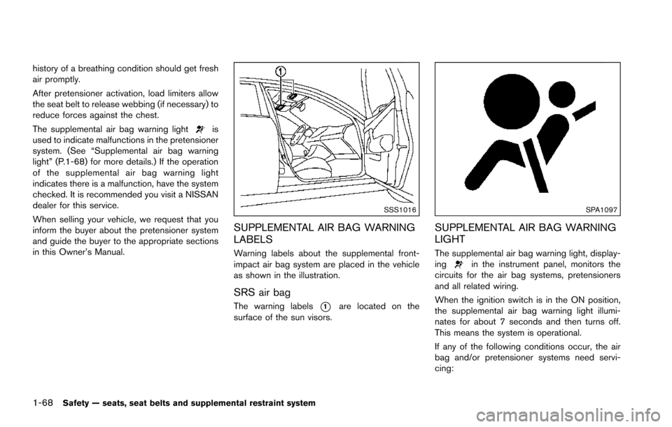
SSS1016
SUPPLEMENTAL AIR BAG WARNING
LABELS
Warning labels about the supplemental front-
impact air bag system are placed in the vehicle
as shown in the illustration.
SRS air bag
The warning labels*1are located on the
surface of the sun visors.
SPA1097
SUPPLEMENTAL AIR BAG WARNING
LIGHT
The supplemental air bag warning light, display-
ingin the instrument panel, monitors the
circuits for the air bag systems, pretensioners
and all related wiring.
When the ignition switch is in the ON position,
the supplemental air bag warning light illumi-
nates for about 7 seconds and then turns off.
This means the system is operational.
If any of the following conditions occur, the air
bag and/or pretensioner systems need servi-
cing:
Page 90 of 614
2 Instruments and controls
Cockpit ........................................................................\
................ 2-3
Instrument panel ........................................................................\
2-4
Meters and gauges ................................................................... 2-5Speedometer and odometer ............................................ 2-6
Tachometer ........................................................................\
... 2-7
Engine coolant temperature gauge ................................ 2-7
Fuel gauge ........................................................................\
.... 2-8
Engine oil pressure gauge ................................................ 2-8
Voltmeter ........................................................................\
........ 2-9
Meter/ring illumination and needle sweep .................... 2-9
Warning lights, indicator lights and
audible reminders ................................................................... 2-10 Checking lights ................................................................. 2-11
Warning lights ................................................................... 2-11
Indicator lights ................................................................... 2-17
Audible reminders ............................................................ 2-20
Vehicle information display .................................................. 2-20 Operational indicators ..................................................... 2-23
Maintenance indicators ................................................... 2-26
Trip computer .................................................................... 2-27
Security systems .................................................................... 2-30 Vehicle Security System ................................................. 2-30
NISSAN Vehicle Immobilizer System .......................... 2-31 Wiper and washer switch ................................................... 2-32
Windshield wiper and washer operation ................. 2-33
Rain-sensing auto wiper system (if
so equipped) ................................................................... 2-34
Rear window wiper and washer operation .............. 2-35
Rear window and outside mirror (if so equipped)
defroster switch ..................................................................... 2-36
Windshield deicer switch (if so equipped) .................... 2-36
Headlight and turn signal switch ....................................... 2-37 Headlight switch ............................................................ 2-37
Instrument brightness control ..................................... 2-40
Turn signal switch .......................................................... 2-41
Fog light switch (if so equipped) .............................. 2-42
Heated steering wheel (if so equipped) ......................... 2-42
Horn ........................................................................\
.................. 2-43
Heated seats ........................................................................\
.. 2-43 Front (if so equipped) ................................................... 2-44
Rear (if so equipped) .................................................... 2-44
Climate controlled seats (if so equipped) ...................... 2-45
Warning systems switch (if so equipped) ...................... 2-46
Sonar system OFF switch (if so equipped) ................... 2-47
SNOW mode switch ............................................................ 2-47
TOW mode switch ................................................................ 2-47
Page 93 of 614
2-4Instruments and controls
JVC0957X
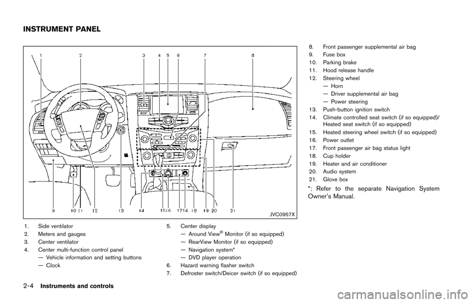
1. Side ventilator
2. Meters and gauges
3. Center ventilator
4. Center multi-function control panel— Vehicle information and setting buttons
— Clock 5. Center display
— Around View�ŠMonitor (if so equipped)
— RearView Monitor (if so equipped)
— Navigation system*
— DVD player operation
6. Hazard warning flasher switch
7. Defroster switch/Deicer switch (if so equipped) 8. Front passenger supplemental air bag
9. Fuse box
10. Parking brake
11. Hood release handle
12. Steering wheel
— Horn
— Driver supplemental air bag
— Power steering
13. Push-button ignition switch
14. Climate controlled seat switch (if so equipped)/ Heated seat switch (if so equipped)
15. Heated steering wheel switch (if so equipped)
16. Power outlet
17. Front passenger air bag status light
18. Cup holder
19. Heater and air conditioner
20. Audio system
21. Glove box
*: Refer to the separate Navigation System
Owner’s Manual.
INSTRUMENT PANEL
Page 94 of 614
SIC4368
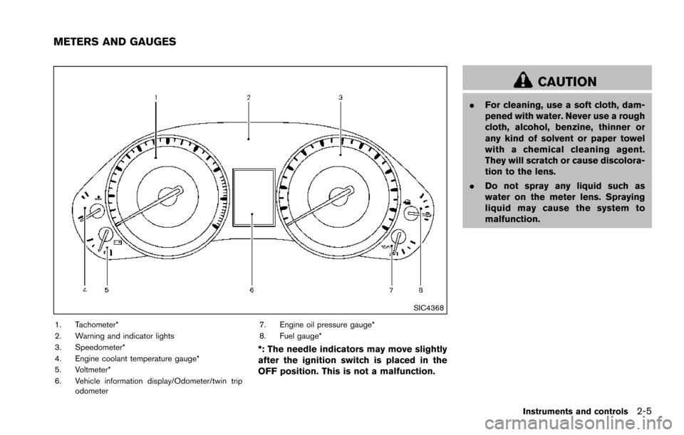
1. Tachometer*
2. Warning and indicator lights
3. Speedometer*
4. Engine coolant temperature gauge*
5. Voltmeter*
6. Vehicle information display/Odometer/twin tripodometer 7. Engine oil pressure gauge*
8. Fuel gauge*
*: The needle indicators may move slightly
after the ignition switch is placed in the
OFF position. This is not a malfunction.
CAUTION
.
For cleaning, use a soft cloth, dam-
pened with water. Never use a rough
cloth, alcohol, benzine, thinner or
any kind of solvent or paper towel
with a chemical cleaning agent.
They will scratch or cause discolora-
tion to the lens.
. Do not spray any liquid such as
water on the meter lens. Spraying
liquid may cause the system to
malfunction.
Instruments and controls2-5
METERS AND GAUGES
Page 95 of 614
2-6Instruments and controls
SIC4369Speedometer
SPEEDOMETER AND ODOMETER
Speedometer
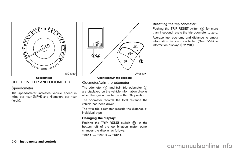
The speedometer indicates vehicle speed in
miles per hour (MPH) and kilometers per hour
(km/h) .
JVI0543XOdometer/twin trip odometer
Odometer/twin trip odometer
The odometer*1and twin trip odometer*2are displayed on the vehicle information display
when the ignition switch is in the ON position.
The odometer records the total distance the
vehicle has been driven.
The twin trip odometer records the distance of
individual trips.
Changing the display:
Pushing the TRIP RESET switch
*3at the
bottom left of the combination meter panel
changes the display as follows:
TRIP A ?TRIP B ?TRIP A Resetting the trip odometer:
Pushing the TRIP RESET switch
*3for more
than 1 second resets the trip odometer to zero.
Average fuel economy and distance to empty
information is also available. (See “Vehicle
information display” (P.2-20) .)