2017 MERCEDES-BENZ G-Class wheel size
[x] Cancel search: wheel sizePage 21 of 286

Summer tiresinwinter .................. 253
Temperature .................................. 263
TIN (Tire Identification Number)
(definition) ..................................... 269
Tire bead (definition) ...................... 269
Tire pressure (definition) ................ 269
Tire pressures (recommended )...... 268
Tire size (data )............................... 273
Tire size designation, load-bearing
capacity, speed rating .................... 264
Tire tread. ...................................... 252
Tire tread( definition) ..................... 269
Totall oadlim it (definition) ............. 269
Tractio n......................................... 263
Tractio n(definition) ....................... 269
Tread wear ..................................... 263
TWR (permissibl etraile rdrawbar
noseweight) (definition) ................. 269
Uniform Tire Quality Grading
Standard s...................................... 263
Uniform Tire Quality Grading
Standard s(de finition) .................... 267
Wea rindicator (definition) ............. 269
Wheel and tire combination ........... 273
Wheel rim (definition) .................... 268
see Fla ttire
Top Tether ............................................ 52
Tow-starting
Emergency engine starting ............ 248
Important safety notes .................. 246
Towin gatrailer
Axle load ,permissibl e.................... 284
Cleaning the traile rtow hitch ......... 235
Coupling up atraile r...................... 154
Decoupling atraile r....................... 155
Driving tip s.................................... 151
Important safety notes .................. 149
Installing the ball coupling ............. 152
Lights display message .................. 176
Pulling away with atraile r.............. 105
Shift rang e..................................... 113
Trailer load s................................... 284
Trailer tow hitch ............................. 284
Towin gaway
Important safety guideline s........... 246
In the event of malfunctions .......... 248
With both axle
s on the ground ....... 247 Towin
geye
Front .............................................. 247
Rear ............................................... 247
Trafficr eports
see also Digital Operator's Man-
ua l.................................................. 198
Trailer
7-pi nconnecto r............................. 156
Power supply ................................. 156
Trailer coupling
see Towing atrailer
Trailer loads
Technical data ............................... 284
Trailer loads and drawbar nose-
weights ............................................... 155
Trailer tow hitch
Ballposition ................................... 284
Trailer towing
ESP
®................................................ 60
PARKTRONIC ................................. 142
Permissibl etraile rloads and
drawbar noseweights ..................... 155
Transfer case
Generaln otes ................................ 145
Shift rang e..................................... 145
Shifting .......................................... 146
Shifting (general notes). ................. 146
Shifting (important safety notes). .. 146
Shifting to neutral .......................... 147
Switching off the off-road gear
rati o............................................... 146
Switching on the off-road gear
rati o............................................... 146
Transmission
see Automati ctransmission
Transmissio npositions .................... 112
Transporting the vehicle .................. 247
Traveling uphill
Brow of hill ..................................... 130
Trim piece s(clea ning instruc-
tions) .................................................. 236
Trip computer (on-board com-
puter) .................................................. 160
Trip odometer
Calling up ....................................... 160
Resetting (on-board computer) ...... 160
Index19
Page 23 of 286
Warranty.............................................. 24
Washer fluid
Display message ............................ 187
Weather display (COMAND)
see als oDigita lOperator's Man-
ua l.................................................. 198
Wheel and tire combinations
Tires. .............................................. 273
Wheel bol ttightening torque ........... 272
Wheels
Changing awheel .......................... 269
Checking ........................................ 251
Cleaning ......................................... 233
Important safety notes .................. 251
Informatio nondriving .................... 251
Interchanging/changing ................ 269
Mounting anew wheel ...................2 72
Mounting awheel .......................... 270
Removing awheel .......................... 272
Snow chains .................................. 253
Storing ...........................................2 70
Tightening torque. .......................... 272
Wheels ize/tire size ....................... 273
Windowc urtain air bag
Display message ............................ 174
Operation ......................................... 46
Windows
see Side windows
Windshield
Defrosting ........................................ 99
Windshiel dheating .............................9 9
Windshield washe rfluid
see Windshieldw asher system
Windshield washe rsystem
Adding washer flui d....................... 229
Notes. ............................................ 280
Windshiel dwipers
Problem (malfunction) ..................... 94
Rear window wipe r.......................... 93
Replacing the wipe rblade s.............. 93
Switching on/off. ............................. 92
Winter driving
Important safety notes .................. 252
Slippery roads urfaces ................... 126
Snow chains .................................. 253
Winter operation
Overview ........................................ 252
Radiato rcover. .............................. 226 Summer tire
s................................. 253
Winter tires
M+S tire s....................................... 253
Wipe rblades
Cleaning ......................................... 234
Important safety notes .................... 93
Replacing ......................................... 93
Wo
oden trim (cleaning instruc-
tions) .................................................. 236
Index21
Page 51 of 286
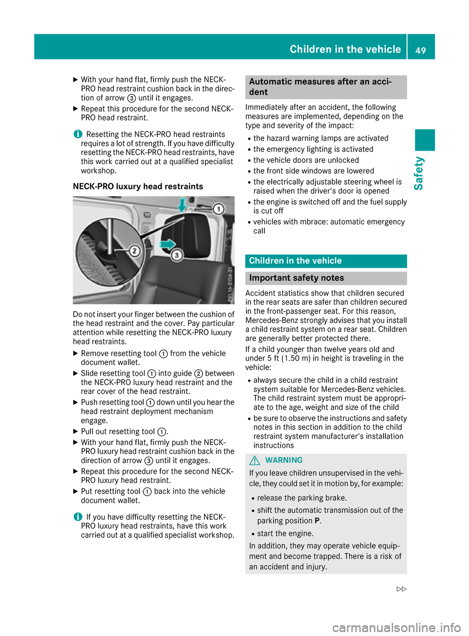
XWith your hand flat, firmly push the NECK-
PRO head restraint cushion back in the direc-tion of arrow =until it engages.
XRepeat this procedure for the secondN ECK-
PRO head restraint.
iResettin gthe NECK-PRO head restraints
requires alot of strength. If you have difficulty
resetting the NECK-PRO head restraints, have
this work carried out at aqualified specialist
workshop.
NECK-PRO luxuryh ead restraints
Do not insert your finger between the cushion of
the head restraint and the cover. Pay particular
attention while resetting the NECK-PRO luxury
head restraints.
XRemove resetting tool :from the vehicle
document wallet.
XSlide resetting tool :into guide ;between
the NECK-PRO luxury head restraint and the
rear cover of the head restraint.
XPush resetting tool :down until you hear the
head restraint deployment mechanism
engage.
XPull out resetting tool :.
XWith your hand flat, firmly push the NECK-
PRO luxury head restraint cushion back in the
direction of arrow=until it engages.
XRepeat this procedure for the secondN ECK-
PRO luxury head restraint.
XPut resetting tool :back into the vehicle
document wallet.
iIf you have difficulty resetting the NECK-
PRO luxury head restraints, have this work
carried out at aqualified specialist workshop.
Automatic measures after an acci-
dent
Immediately after an accident ,the following
measures are implemented, depending on the
type and severityoft he impact:
Rthe hazard warning lamps are activated
Rthe emergency lighting is activated
Rthe vehicle doors are unlocked
Rthe frontside windows are lowered
Rthe electrically adjustable steerin gwheel is
raised when the driver's door is opened
Rthe engine is switched off and the fuel supply
is cut off
Rvehicles with mbrace: automatic emergency
call
Children in the vehicle
Important safety notes
Accident statistics show that children secured
in the rear seats are safer than children secured
in the front-passenger seat. For this reason,
Mercedes-Benz strongly advises that you install
ac hild restraint system on arear seat. Children
are generally better protected there.
If ac hild younger than twelve years old and
under 5ft(1.50m )inh eight is travelin ginthe
vehicle:
Ralwayss ecure the child in achild restraint
system suitable for Mercedes-Benz vehicles.
The child restraint system must be appropri-
ate to the age, weight and size of the child
Rbe sure to observe the instruction sand safety
notes in this section in addition to the child
restraint system manufacturer's installation
instructions
GWARNING
If you leave children unsupervised in the vehi-
cle, they could set it in motion by, for example:
Rrelease the parking brake.
Rshift the automatic transmission out of the
parking position P.
Rstart the engine.
In addition, they may operate vehicle equip-
ment and become trapped. There is arisk of
an accident and injury.
Children in the vehicle49
Safety
Z
Page 61 of 286
4ETS (Electronic Traction System)
iObserve the "Important safety notes" sec-
tion (Ypage 57).
4ET Straction contro lispart of ESP
®.
4ET Straction contro lisnolonger activ eabove a
speed of approximately 37 mph (60 km/h).
Traction contro lbrakes the drive wheels indi-
vidually if they spin. This enables you to pull
away and accelerate on slippery surfaces,f or
example if the road surface is slippery on one
side. In addition, more drive torque is transfer-
red to the wheel or wheels with traction.
Traction contro lremains active, even if you
deactivate ESP
®.
Importan tsafetyn otes
iObserve the "Important safety notes" sec-
tion (Ypage 57).
GWARNING
If ESP
®is malfunctioning, ESP®is unable to
stabilize the vehicle. Additionally, further driv-
ing safety systems are deactivated. This
increases the risk of skiddin gand an accident.
Driv eonc arefully. Have ESP
®checked at a
qualified specialist workshop.
!Only operate the vehicle for amaximum of
ten seconds on abrake test dynamometer.
Switc hoff the ignition.
Application of the brakes by ESP
®may oth-
erwise destroy the brake system.
!Af unction or performanc etest should only
be carried out on atwo-axle dynamometer.
Beforey ou operate the vehicle on such a
dynamometer, please consult aqualified
workshop. You could otherwise damage the
drive train or the brake system.
If the å ESP
®OFF warning lamp lights up
continuously, ESP®is deactivated.
If the ÷ ESP®warning lamp lights up contin-
uously, ESP®is not available due to amalfunc-
tion.
Observe the information on warning lamps
(
Ypage 191) and display messages which may
be displayed in the instrument cluster
(
Ypage 171). Only use wheels with the recommended tire
sizes. Only then will ESP
®function properly.
If differential locksa re switched on, ABS, BAS
and ESP
®switc hoff automatically.
Characteristics of ESP®
Genera linformation
If the ÷ ESP®warning lamp goes out before
beginning the journey, ESP®is automatically
active.
If ESP
®intervenes, the ÷ESP®warning lamp
flashes in the instrument cluster.
If ESP
®intervenes:
XDo not deactivate ESP®under any circum-
stances.
XOnly depress the accelerator pedal as far as
necessary when pulling away.
XAdapt your drivings tyle to suit the prevailing
road and weather conditions.
ECO start/stop function
The ECO start/stop function switches the
engin eoff automatically when the vehicle stops
moving. The engin estart sautomatically when
the driver wants to pull away again. ESP
®
remains in its previously selected status, e.g. if
ESP®was deactivated before the engin ewas
automatically switched off.
Deactivating/activating ESP®
Important safetyn otes
iObservethe "Important safety notes" sec-
tion (Ypage 57).
You can select between the following states of
ESP
®:
RESP®is activated.
RESP®is deactivated.
GWARNING
If you deactivate ESP
®,E SP®no longer sta-
bilizes the vehicle. There is an increased risk
of skiddin gand an accident.
Only deactivate ESP
®in the situation sdescri-
bed in the following.
Driving safetys ystems59
Safety
Z
Page 83 of 286
If somebodybecomes trapped:
Rpress one of the memory function position
buttons, or
Rpress one of the memory function memory
buttons, or
Rmove the switch for steering wheel adjust-
ment in the opposite direction to that in
which the steering wheel is moving
The adjustment process is stopped.
GWARNING
If you drive off whilet he EASY-ENTRY/EXIT
feature is making adjustments, you could lose
control of the vehicle.T here isarisk of an
accident.
Alway swaitu ntil the adjustment process is
complete before driving off.
!Do not activate the EASY-ENTRY/EXIT fea-
ture, if the seat backrest is reclined too far
backwards. This can damage the front or rear
seats. You must first move the backrest to a
vertical position.
The EASY-ENTRY/EXIT feature makes getting in
and out of you rvehicle easier.
You can activate and deactivate the EASY-
ENTRY/EXIT feature in the on-board computer
(
Ypage 166).
Position of the steering whee lwhen the
EASY-ENTRY/EXIT feature is active
The steering wheel moves upwards and towards
the dashboard if:
Ryou remove the SmartKey from the ignition
lock or
Ryou open the driver's door and the SmartKey
is in position 0or 1in the ignition lock
iThe steering wheel only moves upwards and
towards the dashboard if it has not already
reached the uppers teering limiter.
Position of the steering whee lfor driv-
ing
The steering wheel is moved to the last selected positionw hen:
Rthe driver's door is closed
Ryou insert the SmartKey into the ignition lock
The last positionoft he steering column is stored
when you switch off the ignition or when you
store the setting with the memory function
(
Ypage 83).
Mirrors
Rear-view mirror
XAdjust the rear-view mirror in such away that
you have agood view of road and traffic con-
ditions behind you.
Exteriorm irrors
Adjusting the exterio rmirrors
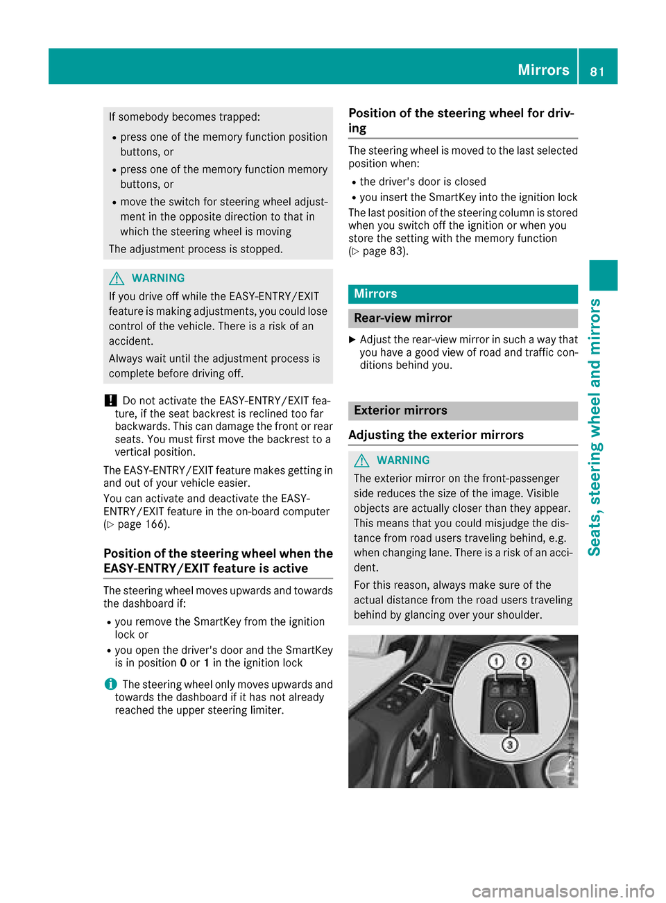
GWARNING
The exterior mirror on the front-passenger
side reduces the size of the image.V isible
objects are actually closer than they appear.
This means that you could misjudge the dis-
tance from road users traveling behind, e.g.
when changing lane. There is arisk of an acci-
dent.
For this reason, always make sure of the
actual distance from the road users traveling
behind by glancing over you rshoulder.
Mirrors81
Seats, steeringw heel and mirrors
Z
Page 234 of 286
cleaning agents. These cleaning agents can
damagethe paintwork or plasti cparts.
!Make sure that the automatic car wash is
suitablef or the size of the vehicle .Fold in the
exterior mirrors before the vehicle is washed.
The exterior mirrors could otherwise be dam-
aged.
!Make sure that the automatic transmission
is in position Nwhe nwashing your vehicle in
at ow-through car wash. The vehicle could be
damaged if the transmission is in another
position.
!Make sure that:
Rthe sid ewindow sand the sliding sunroof
are fully closed.
Rthe blower is switched off.
Rthe windshield wiper switch is at position 0.
The vehicle may otherwise be damaged.
You can wash the vehicle in an automatic car
wash from the very start.
If the vehicle is very dirty, pre-wash it before
cleaning it in an automatic car wash.
After using an automatic car wash, wipe off wax
from the windshield and the wiper blades. This
will prevent smears and reduce wiping noises
caused by residueont he windshield.
Washing by hand
In some countries,washing by hand is only
allowed at speciall yequipped washing bays.
Observe the legalr equirements in each country.
Whenu sing the vehicle in winter, remove all
trace sofroads altd eposits carefully and as
soona spossible.
Whenw ashing the underside of the vehicle ,also
clean the insides of the wheels.
XDo not us ehot water and do not wash the
vehicle in direct sunlight.
XUse asoft sponge to clean.
XUse amildc leaning agent, such as acar
shampooa pproved by Mercedes-Benz.
XThoroughlyh osedownthe vehicle with agen-
tle jet of water.
XDo not point the water jet directlyt owards the
ai ri nlet.
XUse plenty of water and rinse outt he sponge
frequently.
XRinse the vehicle with clean water and dry
thoroughly with achamois.
XDo not le tthe cleaning agent dry on the paint-
work.
Powe rwashers
GWARNING
The water jet from acircula rjet nozzle (dirt
blasters) can cause invisible exterior damage
to the tire sorchassisc omponents. Compo-
nents damaged in this wa ymay fai lunexpect-
edly. There is ariskofana ccident.
Do not us epower washers with circula rjet
nozzle stoclean the vehicle .Have damaged
tire sorc hassisc omponents replaced imme-
diately.
!Alway smaintainad istance of at least
11.8 in (30 cm )between the vehicle and the
power washern ozzle.Information aboutt he
correct distance is available from the equip-
ment manufacturer.
Move the power washern ozzle around when
cleaning your vehicle.
Do not ai mdirectlyata ny of the following:
RTires
RDoor gaps, roof gaps, joints, etc.
RElectrical components
RBattery
RConnectors
RLamps
RSeals
RTrim
RVentilation slots
Damaged seals or electrical components can
lead to leaks or failures.
!Vehicles with decorative film: parts of your
vehicle are covered with adecorative film.
Maintain adistance of at least 27.5 in (70 cm)
between the parts of the vehicle covered with
the fil mand the nozzle of the hig hpressure
cleaner.
Information aboutt he correct distance is
available from the equipment manufacturer.
Move the power washern ozzle around when
cleaning your vehicle.
232Care
Maintenancea nd care
Page 241 of 286
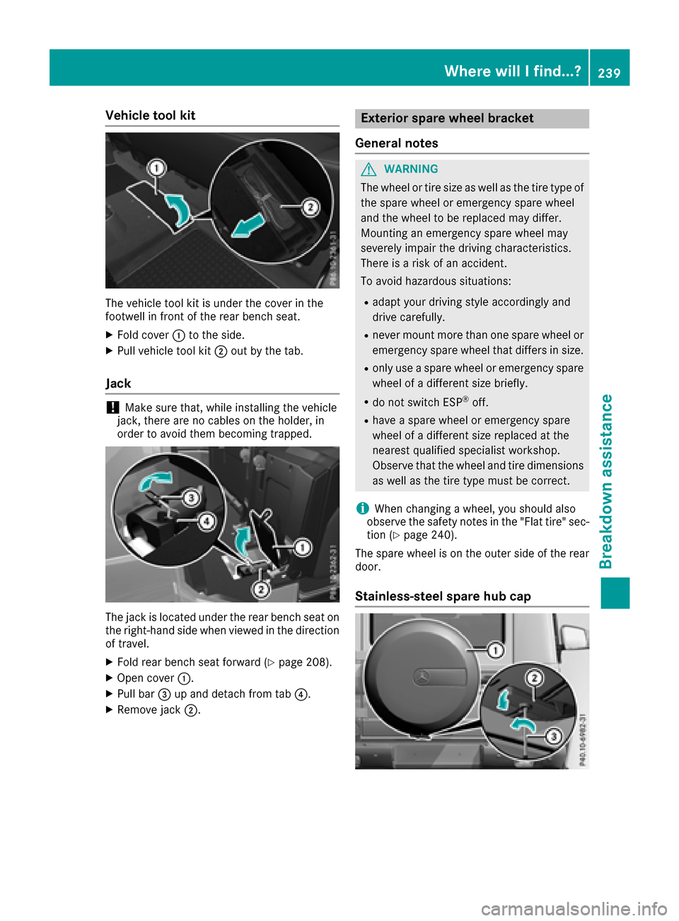
Vehicletoolkit
The vehicl etool kit is under the coverint he
footwell in front of the rearb ench seat.
XFoldc over:to the side.
XPull vehicl etool kit ;outb ythe tab.
Jack
!Make sure that, whil einstalling the vehicle
jack, ther eare no cable sonthe holder, in
order to avoid them becoming trapped.
The jack is locate dunder the rearb ench sea ton
the right-hand side when viewe dinthe direction
of travel.
XFoldr earb ench sea tforward (Ypage 208).
XOpe ncover :.
XPull bar =up and detach from tab ?.
XRemove jack;.
Exterior spare whee lbracket
General notes
GWARNING
The whee lortire size as well as the tire typ eof
the spare whee loremergency spare wheel
and the whee ltobereplaced mayd iffer.
Mounting an emergency spare whee lmay
severely impai rthe driving characteristics.
There is ariskofana ccident.
To avoid hazardouss ituations:
Radap tyou rd riving style accordinglya nd
drive carefully.
Rneve rmount more thano ne spare wheelor
emergency spare whee lthatd iffer sins ize.
Ronlyu seaspare whee loremergency spare
whee lofad ifferent size briefly.
Rdo not switch ESP®off.
Rhave aspare whee loremergency spare
whee lofad ifferent size replaced at the
nearestq ualified specialist workshop.
Observe thatt he wheeland tire dimensions
as well as the tire typ emustbec orrect.
iWhenchanging awheel ,you shoul dalso
observe the safety notes in the "Flat tire "sec-
tio n(
Ypage 240).
The spare whee lisonthe outer side of the rear
door.
Stainless-stee lspare hub cap
Where will Ifind...?239
Breakdo wn assis tance
Z
Page 254 of 286

Rbulges on tires
Rdeformation or severe corrosion on wheels
Regularly checkt he tire tread depth and the
condition of the tread across the whole width of
the tire (
Ypage 252). In order to inspec tthe
inne rside of the tire surface, turn the steering
wheel to full lock.
All wheels must have avalve cap to protect the
valve against dirt and moisture. Do not install
anythin gontot he valve other than the standard
valve cap or avalve cap approved by Mercedes-
Benzf or your vehicle. Do not use any other valve
caps or systems ,e.g. tire pressure monitoring
systems.
You should regularly checkt he pressure of all
your tires includin gthe spare wheel, particularly
prior to long trips. Adjust the tire pressure as
necessary (
Ypage 254).
The servicel ife of tires depends, among other
things, on the following factors:
RDriving style
RTire pressure
RDistance covered
Notes on tir etread
GWARNING
Insufficientt ire tread will reduce tire traction.
The tire is no longer able to dissipate water.
This means that on wet road surfaces,t he risk
of hydroplaning increases, in particular where speed is not adapted to suit the driving con-
ditions. There is arisk of accident.
If the tire pressure is too high or too low, tires
may exhibit differentl evels of wear at differ-
ent location sonthe tire tread. Thus, you
should regularly checkt he tread depth and
the condition of the tread across the entire
width of all tires.
Minimum tire tread depth for:
RSummer tires: âin (3 mm)
RM+S tires: ãin (4 mm)
For safety reasons ,replace the tires before
the legally prescribed limit for the minimum
tire tread depth is reached.
Marking :shows where the bar indicator
(arrow) for tread wear is integrated int othe tire
tread.
Treadwear indicators (TWI) are required by law. Six indicators are positioned on the tire tread.
They are visible onc eatread depth of approx-
imately áin (1.6 mm) has been reached. If this
is the case, the tire is so worn that it must be
replaced.
Selecting, mounting and replacing
tires
ROnly mount tires and wheels of the same type
and make.
ROnly mount tires of the correct size ont othe
wheels.
RBreak in new tires at moderates peeds for the
first 60 miles (100 km). The new tires only
reach their full performanc eafter this dis-
tance.
RDo not drive with tires which have too little
tread depth, as this significantly reduces the
traction on wet roads (hydroplaning).
RReplace the tires after six years at the latest,
regardless of wear. This also applies to the
spare wheel.
Winter operation
General notes
Have your vehicle winter-proofed at aqualified
specialist workshop at the onset of winter.
Observe the notes in the "Changing awheel"
section (
Ypage 269).
252Winter operation
Wheels and tires