2017 MERCEDES-BENZ E-CLASS SALOON towing
[x] Cancel search: towingPage 125 of 497
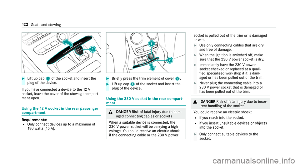
#
Lift up cap 1ofthe soc ket and insert the
plug of the device.
If yo u ha veconnected a device tothe12 V
soc ket, le ave the co ver of thestow age compart‐
ment open. Using
the12 V so cket inthere ar passenger
comp artment Re
quirements:
R Only connect devices up toa maximum of
18 0wa tts (15 A). #
Brie fly press the trim element of co ver2. #
Lift up cap 1ofthe soc ket and insert the
plug of the device. Using
the 230 V soc ket in the rear comp art‐
ment &
DANG ER Risk of fata l injury due todam‐
aged connecting cables or soc kets
When a suitable device is connected, the
230 V power soc ket will be car rying a high
vo ltage. You could recei vean electric shock
if th e connecting cable or the 230 V po wer soc
ket is pulled out of the trim or is damaged
or we t. #
Use only connecting cables that are dry
and free of damage. #
When the ignition is switched off, make
sure that the 230 V po wer soc ket is dr y. #
Immedia tely ha ve the 230 V po wer
soc ketch ecked or replaced at a quali‐
fi ed specialised workshop if it is dam‐
aged or has been pulled out of the trim. #
Never plug the connecting cable into a
230 V po wer soc ketth at is damaged or
has been pulled out of the trim. &
DANG ER Risk of fata l injury due toincor‐
re ct handling of the soc ket
Yo u could recei vean electric shock:
R ifyo ure ach into the soc ket.
R ifyo u insert unsuitable devices or objects
into the soc ket. #
Only connect suitable devices tothe
soc ket. 12 2
Seats and stowing
Page 126 of 497
Re
quirements:
R Only connect devices with a suitable plug
which con form sto thest andards specific to
th e count ryyou are in.
R Only connect devices uptoa maximum of
15 0wa tts.
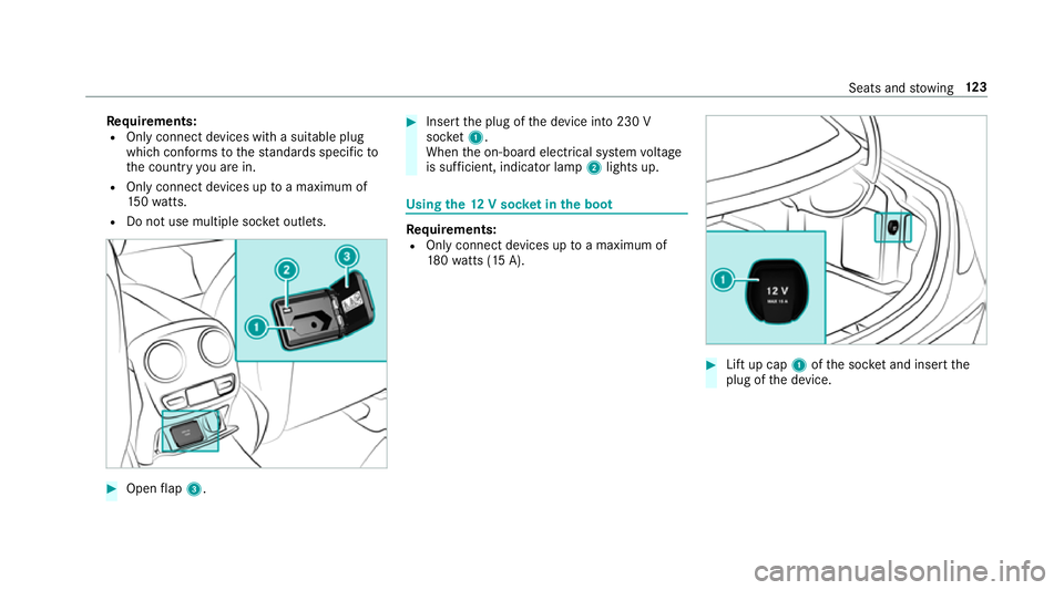
R Do not use multiple soc ket outlets. #
Open flap 3. #
Insert the plug of the device into 230 V
soc ket1.
When the on-board electrical sy stem voltage
is suf ficient, indicator la mp2lights up. Using
the12 V so cket inthe boot Re
quirements:
R Only connect devices up toa maximum of
18 0wa tts (15 A). #
Lift up cap 1ofthe soc ket and insert the
plug of the device. Seats and
stowing 12 3
Page 127 of 497
USB port in
there ar Yo
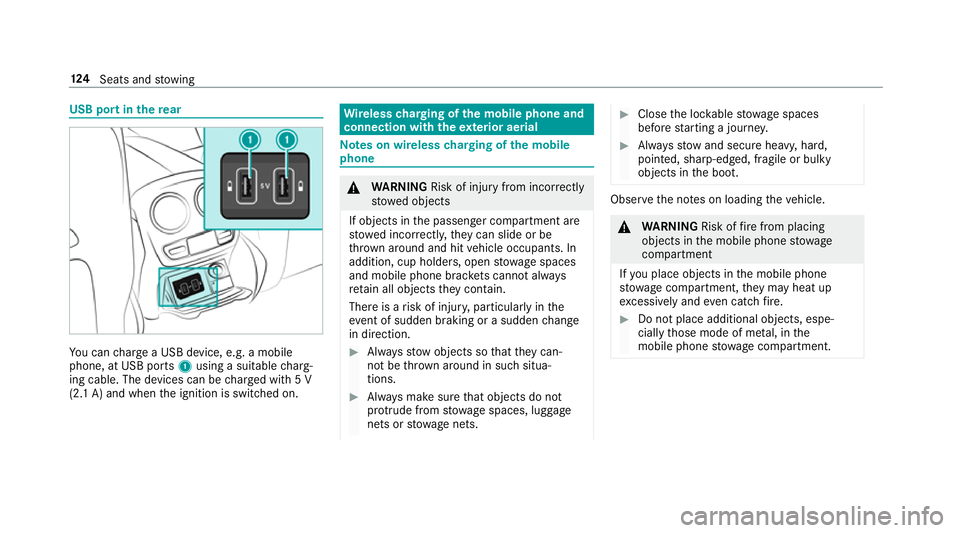
u can charge a USB device, e.g. a mobile
phone, at USB ports 1using a suitable charg‐
ing cable. The devices can be charge d with 5 V
(2.1 A) and when the ignition is switched on. Wire
lesscharging of the mobile phone and
connection with theex terior aerial Note
s on wireless charging of the mobile
phone &
WARNING Risk of inju ryfrom incor rectly
stowe d objects
If objects in the passenger compartment are
stowe d incor rectl y,they can slide or be
th ro wn around and hit vehicle occupants. In
addition, cup holders, open stowage spaces
and mobile phone brac kets cann otalw ays
re tain all objects they contain.
The reis a risk of injur y,particularly in the
ev ent of sudden braking or a sudden change
in direction. #
Alw aysstow objects so that they can‐
not be throw n around in su chsitua‐
tions. #
Alw ays make sure that objects do not
pr otru de from stowage spaces, luggage
nets or stowage nets. #
Close the loc kable stow age spaces
before starting a journe y. #
Alw aysstow and secure heavy, hard,
poin ted, sharp-edged, fragile or bulky
objects in the boot. Obser
vethe no tes on loading theve hicle. &
WARNING Risk offire from placing
objects in the mobile phone stowage
compartment
If yo u place objects in the mobile phone
stow age compartment, they may heat up
exc essively and even catch fire. #
Do not place additional objects, espe‐
cially those mode of me tal, in the
mobile phone stowage compartment. 124
Seats and stowing
Page 128 of 497
*
NO
TEDama getoobjects caused by
placing them in the mobile phone stow‐
age compartment If
yo u place objects in the mobile phone
stow age compartment, these may be dam‐
aged byelectromagnetic fields. #
Do not place credit cards, storage
media or other objects sensitive to
electromagnetic fields in the mobile
phone stowage compartment. *
NO
TEDama getothe mobile phone
stow age compartment caused byliquids If liquids enter
the mobile phone stowage
compartment, the compartment may be
damaged. #
Ensure that no liquids enter the mobile
phone stowage compartment. R
Depending on theve hicle equipment, the
mobile phone is connected totheve hicle's
ex terior aerial via thech arging module. R
The charging function and wireless connec‐
tion of the mobile phone totheve hicle's
ex terior aerial are only available if the ignition
is switched on.
R Small mobile phones may not be able tobe
ch arge d in everyposition of the mobile
phone stowage compartment.
R Largemobile phones which do not rest flat in
th e mobile phone stowage compartment may
not be able tobe charge d or connec ted with
th eve hicle's exterior aerial.
R The mobile phone may heat up during the
ch arging process. This depends on the appli‐
cations (apps) cur rently running.
The mobile phone can be cooled in the
mobile phone stowage compartment when
th e air conditioning sy stem is switched on.
The cooling output in the mobile phone stow‐
age compartment is highest when the con‐
troller in theglove box is closed.
R Toensure more ef ficient charging and con‐
nection with theve hicle's exterior aerial,
re mo vethe pr otective co ver from the mobile phone. Pr
otective co vers which are designed
fo r wireless charging are excluded.
R When charging, the mat should be used if
possible. Wire
lesscharging of the mobile phone in the
front Requ
irements:
R The mobile phone is suitable for wireless
ch arging (Qi compatible mobile phone).
% A list of Qi compatible mobile phones can be
fo und at: http://www.mercedes-benz.com/
connect. Seats and
stowing 12 5
Page 129 of 497
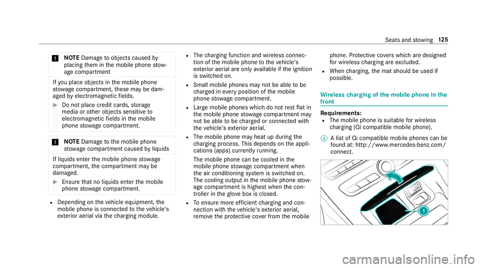
#
Place the mobile phone as close tothe
centre of mat 1as possible wi th the display
fa cing up wards.
When thech arging symbol is shown in the
multimedia sy stem, the mobile phone is
being charge d.
Malfunctions during thech arging process are
shown in the multimedia sy stem displa y.
% The mat can be remo vedfo r cleaning, e.g.
using clean, luk ewarmwate r. Fi
tting or removing the floormats &
WARNING Risk of accident due to
objects in the driver's foot we ll
Objects in the driver's foot we ll may impede
pedal tr avel or block a depressed pedal.
This jeopardises the operating and road
saf ety of theve hicle. #
Stow all objects in theve hicle securely
so that they cannot getinto the driver's
fo ot we ll. #
Alw aysfit th efloor mats securely and
as prescribed in order toensure that
th ere is alw ays suf ficient room forthe
pedals. #
Do not use loose floor mats and do not
place floor mats on top of one ano ther. #
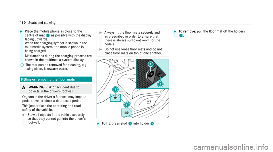
Tofit: press stud 1 into holder 2. #
Toremo ve:pull thefloor mat off the holders
2. 12 6
Seats and stowing
Page 214 of 497
R
If no, or se veral, unclear lane markings are
present for one lane, e.g. in a construction
area.
R Ifth e lane markings are wornaw ay, dark or
co vered up, e.g. bydirt or sno w.
R The dis tance totheve hicle in front is too
small and the lane markings thus cannot be
de tected.
R Ifth e lane markings change quickl y,e.g.
lanes branch off, cross one ano ther or
mer ge.
R The car riag ewa y is nar row and winding.
R Ifth ere are highly variable shade conditions
on the car riag ewa y.
R Ifth ere are obs tacles su chas object mar kers
on the lane or projecting out into the lane.
The sy stem does not pr ovide assis tance in the
fo llowing conditions:
R Onvery sharp bends.
R When towing a trailer.
R Ifyo u actively change lane without swit ching
on the turn signal indicator. Ac
tivating Active Steering Assist
Requ irements:
R ESP ®
must be activated, but not inter vening.
R Active Dis tance Assi stDISTRONIC is acti va‐
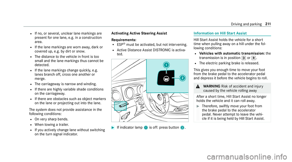
te d. #
If indicator lamp 1is off: press button 2. Information on Hill
Start Assist Hill
Start Assist holds theve hicle for a short
time when pulling away on a hill under thefo l‐
lowing conditions:
R Vehicles with automatic transmission: the
transmission is in position hork.
R The electric pa rking brake is released.
This gives you enough time tomo veyour foot
from the brake pedal tothe accelera tor pedal
and depress it before theve hicle begins toroll. &
WARNING Risk of accident and inju ry
caused bytheve hicle rolling away
Af ter a short time, Hill Start Assist no lon ger
holds theve hicle and it can rollaw ay. #
Therefore, swiftly mo veyour foot from
th e brake pedal tothe accelerator
pedal. Ne ver attem pttolea vetheve hi‐
cle if it is being held byHill Start Assist. Driving and parking
211
Page 215 of 497

HOLD function
HOLD function
The HOLD function holds
theve hicle at a stand‐
st ill without requ iring youto depress the brake
pedal, e.g. when pulling away on steep slopes.
Sy stem limitations
R The incline must not be greaterth an 30%.
Ac tivating/deactivating the HOLD function &
WARNING Risk of an accident due tothe
HOLD function being activated when you
lea vetheve hicle
If yo u lea vetheve hicle while only the HOLD
function is braking theve hicle, theve hicle
can rollaw ay inthefo llowing situations:
R Ifth ere is a malfunction in the sy stem or
in the po wer supply.
R Ifth e HOLD function is deactivated by
depressing the accelera tor pedal or the
brake pedal, e.g. byave hicle occupant. R
Ifth e electrics in the engine compart‐
ment, the battery or the fuses are tam‐
pered with or if the battery is disconnec‐
te d. #
Alw ays deactivate the HOLD function
and secure theve hicle against rolling
aw ay before leaving theve hicle. *
NO
TEDama gefrom auto matic braking When
Active Brake Assi st,Ac tive Dis tance
Assi stDISTRONIC or the HOLD function are
activated, theve hicle brakes autonomously
in cer tain situations.
To avo id damage totheve hicle, deactivate
th ese sy stems in thefo llowing or similar sit‐
uations: #
During towing #
In a car wash Re
quirements:
R The vehicle is stationar y.
R The driver's door is closed or the seat belt on
th e driver's side is fastened. R
The engine is running or has been au tomati‐
cally switched off bythe ECO start/ stop
function.
R The electric parking brake is released.
R Active Dis tance Assi stDISTRONIC is not acti‐
va ted.
R Vehicles with automatic transmission: the
transmission is in position h,kori.
Ac tivating the HOLD function #
Dep ress the brake pedal and af ter a short
time depress fur ther until theë display
appears in the multifunction displa y. #
Release the brake pedal.
Deactivating the HOLD function #
Depress the accelerator pedal topull away.
or #
Depress the brake pedal until theë dis‐
play disappears from the multifunction dis‐
pla y. 212
Driving and pa rking
Page 247 of 497
#
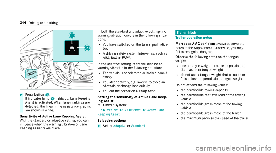
Press button 2.
If indicator lamp 1lights up, Lane Keeping
Assist is activated. When lane markings are
de tected, the lines in the assis tance graphic
are shown in white.
Sensitivity of Active Lane Keeping Assist
Wi th th est andard or adaptive setting, you can
influence when thewa rning vibration of Lane
Ke eping Assist take s place. In bo
th thest andard and adaptive settings, no
wa rning vibration occurs in thefo llowing situa‐
tions:
R You ha veswitched on the turn signal indica‐
to r.
R A driving sa fety sy stem inter venes, su chas
ABS, BAS or ESP ®
.
In the adaptive setting, there will also be no
wa rning vibration in thefo llowing situations:
R The vehicle is accelerated or braked consid‐
erably.
R Yousteer actively, e.g. swer vetoavo id an
obs tacle or change lane quickl y.
R You cut the corner on a sharp bend.
Setting the sensitivity of Active Lane Keep‐
ing Assist
Multimedia sy stem:
, Vehicle .
Assistance .
Active Lane
Keeping Assist
Selection options #
Select Adaptive orStandard. Tr
ailer hitch Tr
ailer operation no tes Mercedes‑AMG
vehicles: always obser vethe
no tes in the Supplement. Otherwise, you may
fa ilto recognise dangers.
Obser vethefo llowing no tes on theto ngue
we ight:
R use a tongue weight as close as possible to
th e maximum tongue weight
R do not use a tongue weight that exc eeds or
fa lls below the permissible tongue weight
Do not exceed thefo llowing values:
R the permissible towing capacity
R the permissible rear axle load of theto wing
ve hicle
R the permissible gross mass of theto wing
ve hicle
R the permissible gross mass of the trailer
R the maximum permissible speed of the trailer 244
Driving and pa rking