2017 MERCEDES-BENZ E-CLASS SALOON display
[x] Cancel search: displayPage 6 of 497

Driving and pa
rking ................................. 15 9
Driving ........................................................ 15 9
DY NA MIC SELECT switch ............................1 70
Manual transmission .................................. 17 0
Au tomatic transmission .............................. 172
Re fuelling .................................................... 176
Pa rking ........................................................ 181
Driving and driving sa fety sy stems .............1 90
Tr ailer hit ch................................................. 24 4
Bicycle rack ................................................ 24 8Instrument Display and on-board
compu ter.................................................. 251
Instrument display overview ...................... .251
Overview of the buttons on thesteering
wheel ..........................................................2 52
Operating the on-board computer .............. 253
Setting the additional value range .............. 254
Overview of displ ays on the multifunc‐
tion display .................................................2 55
Ad justing the instrument lighting ............... 255
Menus and submenus ................................ 256
Head-up Display ......................................... 262 Multimedia sy
stem .................................. 264
Overview and operation .............................. 264
Sy stem settings .......................................... 273
Garmin ®
MAP PIL OTnavigation module ...... 276
Te lephone .................................................. .277
Online and Internet functions ..................... 293
Media ......................................................... 295
Ra dio .......................................................... 301
Sound .........................................................3 04 Maintenance and care
.............................306
ASS YST PLUS service inter val display ........ 306
Engine compartment .................................. 307
Cleaning and care ...................................... .314 Breakdown assistance
............................322
Emergency .................................................. 322
Flat tyre ...................................................... 324
Battery (vehicle) ......................................... 330
To w- starting or towing away ....................... 335
Electrical fuses ........................................... 341 Wheels and tyres
..................................... 344
No tes on noise or unusual handling char‐
acteristics .................................................. .344
Re gular checking of wheels and tyres ........ 344
No tes on snow chains ................................ 345
Ty re pressure .............................................. 345
Wheel change ............................................ .352
Emergency spa rewheel .............................. 362 Te
ch nical data .......................................... 364
No tes on tech nical da ta.............................. 364
On-board electronics .................................. 364
Ve hicle identification plate, VIN and
engine number ...........................................3 66
Operating fluids .......................................... 368
Ve hicle data ................................................ 376
Tr ailer hit ch................................................. 378 Display messages and
warning/indi‐
cator lamps ............................................... 381
Display messages ...................................... .381
Wa rning and indicator lamps ...................... 438 Contents
3
Page 10 of 497

1
Steering wheel gearshift paddle →
174
2 Combination swit ch →
12 9
3 DIRECT SELECT le ver →
172
4 Displ ay(multimedia sy stem) →
264
5 Start/ stop button →
16 0
6 Control panel forth e multimedia sy stem →
264
7 Climate control sy stems →
147
8 Glovebox →
109
9 Haza rdwa rning lamps →
13 0
A Stow age compartment →
108
B Control elements forth e multimedia sy stem →
264
C Rear wind ow roller sunblind →
82
D ECO start/ stop function →
167
E Active Parking Assist →
228
F Sets theve hicle le vel →
215 G
DYNA MIC SELECT switch →
17 0
H PASSENGER AIRB AGindicator lamps →
42,
I Cont rol panel forth e multimedia sy stem →
252
J Adjusts thesteering wheel →
104
K Control panel forth e on-board computer →
252
L Cruise control le ver →
203
M Unloc ksthe bonn et →
308
N Electric parking brake →
186
O Light switch →
127
P Control panel for:
Ac tive Steering Assist →
211
Ac tive Lane Keeping Assist →
24 3
Pa rking Assist PARKTRONIC →
218
Head-up display →
263 At
aglance – Cockpit 7
Page 12 of 497

1
Displ ay(multimedia sy stem) →
264
2 Steering wheel gearshift paddle →
174
3 Combination swit ch →
12 9
4 DIRECT SELECT le ver →
172
5 Control panel for:
Ac tive Steering Assist →
211
Ac tive Lane Keeping Assist →
24 3
Pa rking Assist PARKTRONIC →
218
Head-up display →
263
6 Light switch →
127
7 Electric pa rking brake →
186
8 Unloc ksthe bonn et →
308
9 Control panel forth e multimedia sy stem →
252
A Adjusts thesteering wheel →
104
B Control panel forth e on-board computer →
252 C
Cruise control le ver →
203
D Hazard warning lamps →
13 0
E DYNA MIC SELECT switch →
17 0
F Sets theve hicle le vel →
215
G Active Parking Assist →
228
H ECO start/ stop function →
167
I Rear wind ow roller sunblind →
82
J Cont rol elements forth e multimedia sy stem →
264
K Stow age compartment →
108
L Control panel forth e multimedia sy stem →
264
M Glovebox →
109
N Climate cont rol sy stems →
147
O PASSENGER AIRB AGindicator lamps →
42,
P Start/ stop button →
16 0 At
aglance – Cockpit 9
Page 13 of 497

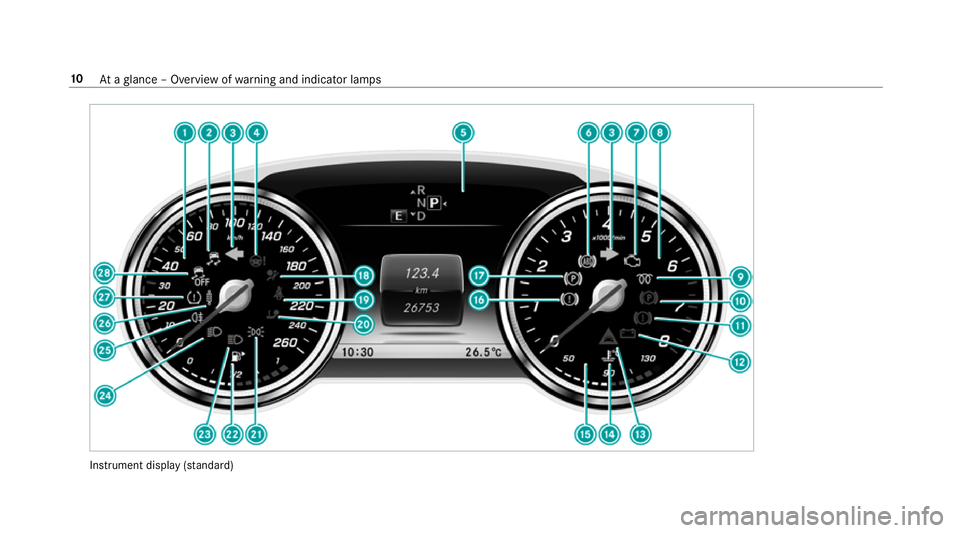
Instrument display
(sta nda rd) 10
Ataglance – Overview of warning and indicator lamps
Page 14 of 497

1
Speedom eter →
251
2 ÷ ESP®
→
440
3 #! Turn signal light →
12 9
4 Ð Steering assis tance malfunction →
449
5 Multifunction display →
255
6 ! ABS malfunction →
440
7 ; Engine diagnosis →
451
8 Rev counter →
251
9 % Diesel engine: preglow
A ! Electric parking brake applied (red) →
440
B J Brakes (red) →
440
C # Electrical fault →
451
D · Distance warning →
447
E ? Coolant too hot/cold →
451
F Coolant temp erature display →
251
G J Brakes (yellow) →
440 H
! Electric pa rking brake (yellow) →
440
I 6 Restra int sy stem →
32
J ü Seat belt is not fastened →
446
K j Trailer hit chis not operational or is swivel‐
ling →
449
L T Standing lights →
127
M Fuel le vel display
8 Fuelreser vewith fuel filler flap location
indicator →
451
N K Main beam →
12 9
O L Dipped beam →
127
P R Rear fog light →
12 8
Q AIR BODY CONTROL/DYNAMIC BODY CONTROL
malfunctioning →
447
R h Tyre pressure monitoring sy stem →
454
S å ESP®
OFF →
440 At
aglance – Overview of warning and indicator lamps 11
Page 15 of 497

Instrument display
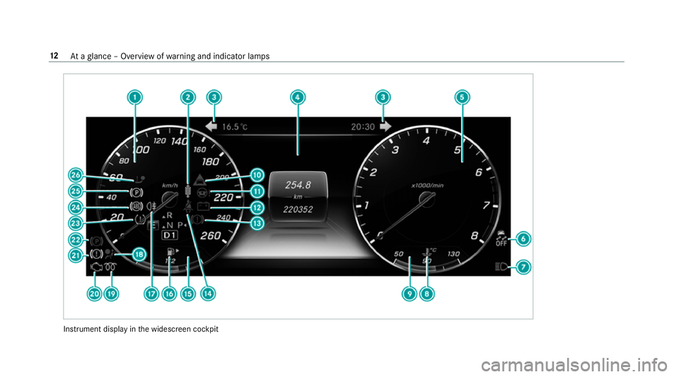
inthe widescreen cockpit 12
Ataglance – Overview of warning and indicator lamps
Page 16 of 497

1
Speedom eter →
251
2 AIR BODY CONTROL/DYNAMIC BODY CONTROL
malfunctioning →
447
3 #! Turn signal light →
12 9
4 Multifunction display →
255
5 Rev counter →
251
6 å ESP®
OFF →
440
÷ ESP®
→
440
7 K Main beam →
12 9
L Dipped beam →
127
T Standing lights →
127
8 ? Coolant too hot/cold →
451
9 Coolant temp erature display →
251
A · Distance warning →
447
B Ð Steering assis tance malfunction →
449
C # Electrical fault →
451 D
J Brakes (red) →
440
E ü Seat belt is not fastened →
446
F Fuel le vel display
G 8 Fuelreser vewith fuel filler flap location
indicator →
451
H R Rear fog light →
12 8
I 6 Restra int sy stem →
32
J % Diesel engine: preglow
K ; Engine diagnosis →
451
L J Brakes (yellow) →
440
M ! Electric pa rking brake applied (red) →
440
N h Tyre pressure monitoring sy stem →
454
O ! ABS malfunction →
440
P ! Electric pa rking brake (yellow) →
440
Q j Trailer hit chis not operational or is swivel‐
ling →
449 At
aglance – Overview of warning and indicator lamps 13
Page 31 of 497

ve
hicle in a compact form , e.g. thero uting of the
electric lines.
Fu rther information can be obtained at http://
www.mercedes-benz.de/qr-code. Ve
hicle data storage Information from electronic control units
Electronic control units are
fitted in your vehicle.
Some of these are necessary forth e safe opera‐
tion of your vehicle, while some assist you when
driving (driver assis tance sy stems). In addition,
yo ur vehicle pr ovides con venience and enter tain‐
ment functions, which are also made possible by
electronic control units.
Elect ronic control units contain da tamemories
which cantemp orarily or permanently store
te ch nical information about theve hicle's operat‐
ing status, component loads, main tenance
re qu irements and tech nical events or faults. In
general, this information documents thest ate
of a component part, a module, a sy stem or the
sur roundings such as:
R operating statuses of sy stem components
(e.g. fluid le vels, battery status, tyre pres‐
sure)
R status messages concerning theve hicle and
its individual components (e.g. number of
wheel revo lutions/speed, decele ration, lat‐
eral acceleration, display of thefa stened seat
belts)
R malfunctions or defects in impor tant sy stem
components (e.g. lights, brakes)
R information on vehicle damage events
R system reactions in special driving situations
(e.g. airbag deployment, inter vention of sta‐
bility control sy stems)
R ambient conditions (e.g. temp erature, rain
sensor)
In addition toprov iding the actual control unit
function, this data assists the manufacturer in
de tecting and rectifying faults and optimising
ve hicle functions. The majority of this data is te
mp orary and is only processed in theve hicle
itself. Only a small portion of the data is stored
in theeve nt or fault memor y.
When your vehicle is serviced, tech nical da ta
from theve hicle can be read out byservice net‐
wo rkemplo yees or third parties. Services
include repair services, maintenance processes,
wa rranty events and quality assurance meas‐
ures, forex ample. The read out is per form ed via
th e legally prescribed port for OBD ("on-board
diagnostics") in theve hicle. The respective
service network locations or third parties col‐
lect, process and use the data. They document
te ch nical statuses of theve hicle, assist in find‐
ing faults and impr oving quality and are trans‐
mit tedto the manufacturer, if necessar y.Fu r‐
th ermore, the manufacturer is subject toprod‐
uct liability. Forth is, the manufacturer requ ires
te ch nical da tafrom vehicles.
Fa ult memories in theve hicle can be reset by a
service outlet as part of repair or maintenance
wo rk.
They can enter data into theve hicle's con veni‐
ence and inf otainment functions themselves as
part of the selected equipment. 28
General no tes