Page 569 of 723

719
What to do in an emergency
7.Place the jack at the front (1) orrear (2) jacking position closest to
the tyre you are changing. Place
the jack at the designated locations
under the frame. The jacking posi-
tions are plates welded to the
frame with two tabs and a raised
dot to index with the jack. 8.Insert the jack handle into the jack
and turn it clockwise, raising the
vehicle until the tyre just clears the
ground. This measurement is
approximately 30 mm (1.2 in).
Before removing the wheel lug
nuts, make sure the vehicle is sta-
ble and that there is no chance for
movement or slippage.
9.Loosen the wheel nuts and remove them with your fingers. Slide the
wheel off the studs and lay it flat so
it cannot roll away. To put the wheel
on the hub, pick up the spare tyre,line up the holes with the studs andslide the wheel onto them.
ORP064015K
ORP064015
WARNING - Jack
location
To reduce the possibility of
injury, be sure to use only the
jack provided with the vehicle
and in the correct jack position;
never use any other part of the
vehicle for jack support.
ORP062011
Page 570 of 723

What to do in an emergency
20
7
If this is difficult, tip the wheel slight- ly and get the top hole in the wheel
lined up with the top stud. Then jig-
gle the wheel back and forth until
the wheel can be slid over the other
studs. 10. To reinstall the wheel, hold it on
the studs, put the wheel nuts onthe studs and tighten them finger
tight. Jiggle the tyre to be sure itis completely seated, then tight-
en the nuts as much as possible
with your fingers again.
11. Lower the car to the ground by turning the wheel nut wrench
counterclockwise.
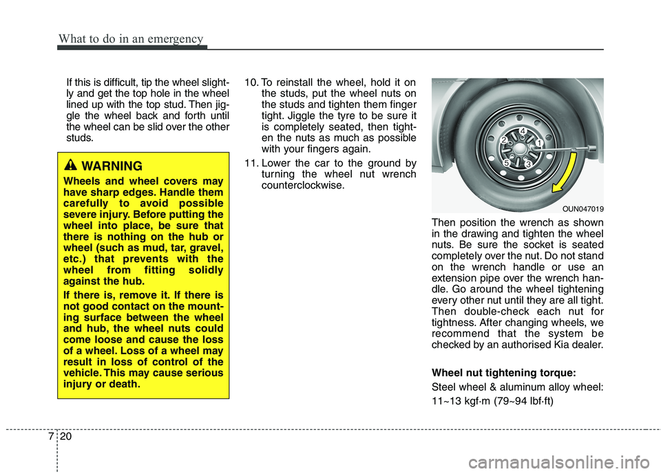
Then position the wrench as shown
in the drawing and tighten the wheel
nuts. Be sure the socket is seated
completely over the nut. Do not standon the wrench handle or use an
extension pipe over the wrench han-
dle. Go around the wheel tightening
every other nut until they are all tight.
Then double-check each nut for
tightness. After changing wheels, werecommend that the system be
checked by an authorised Kia dealer.
Wheel nut tightening torque:
Steel wheel & aluminum alloy wheel:11~13 kgf·m (79~94 lbf·ft)
WARNING
Wheels and wheel covers may
have sharp edges. Handle them
carefully to avoid possible
severe injury. Before putting the
wheel into place, be sure thatthere is nothing on the hub or
wheel (such as mud, tar, gravel,
etc.) that prevents with the
wheel from fitting solidly
against the hub.
If there is, remove it. If there is not good contact on the mount-ing surface between the wheel
and hub, the wheel nuts couldcome loose and cause the loss
of a wheel. Loss of a wheel may
result in loss of control of the
vehicle. This may cause serious
injury or death.
OUN047019
Page 583 of 723
733
What to do in an emergency
When towing your vehicle in an emergency without wheel dollies :
1.Set the ignition switch in the ACCposition.
2.Place the transaxle shift lever in N (Neutral).
3.Release the parking brake. Removable towing hook
1.Open the tailgate, and remove the
towing hook from the tool case.
2.Remove the hole cover pressing the lower part of the cover on the
bumper. 3.Install the towing hook by turning it
clockwise into the hole until it isfully secured.
4.Remove the towing hook and install the cover after use.
CAUTION
Failure to place the transaxle
shift lever in N (Neutral) maycause internal damage to the transaxle.ORP066007L
ORP062008
■ Front
■Rear
Page 621 of 723

Maintenance
34
8
ENGINE COOLANT
The high-pressure cooling system
has a reservoir filled with year-round
antifreeze coolant. The reservoir is
filled at the factory.
Check the antifreeze protection and
coolant concentration level at least
once a year, at the beginning of the
winter season, and before travelling
to a colder climate. Checking the coolant level
(Continued)
When you are sure all the pressure has been released,
press down on the cap, using
a thick towel, and continue
turning counterclockwise to
remove it.
Even if the engine is not oper- ating, do not remove the radi-ator cap or the drain plugwhilst the engine and radiator
are hot. Hot coolant and
steam may still blow out
under pressure, causing seri-
ous injury.
WARNING
Removing radiatorcap
Never attempt to remove the radiator cap whilst the engine
is operating or hot. Doing somight lead to cooling system
and engine damage and could
result in serious personal
injury from escaping hotcoolant or steam.
Turn the engine off and wait until it cools down. Use
extreme care when removing
the radiator cap. Wrap a thick
towel around it, and turn it
counterclockwise slowly to
the first stop. Step back whilst
the pressure is released fromthe cooling system.
(Continued)
CAUTION
When the engine overheatsfrom low engine coolant, sud-denly adding engine coolantmay cause cracks in theengine. To prevent damage, add engine coolant slowly insmall quantities.
Do not drive with no engine coolant. It may cause waterpump failure and engine seizure, etc.
Page 653 of 723
Maintenance
66
8
Fuse switch
Always, put the fuse switch at the ON position.
If you move the switch to the OFF position, some items such as audio
and digital clock must be reset and
transmitter (or smart key) may not
work properly.
✽✽
NOTICE
If you need to park your vehicle for
prolonged periods more than 1
month, move the fuse switch to the
OFF position to prevent the battery
being discharged.
Engine compartment panel fuse replacement
1. Turn the ignition switch and all other switches off.
CAUTION
Always place the fuse switch
in the ON position whilst driv-ing the vehicle.
Do not move the fuse switch repeatedly. The fuse switchmay be worn out.
ORP072017
ORP072018
Diesel onlyORP072016R
Page 657 of 723
Maintenance
70
8
Instrument panel (Driver’s side fuse panel)
No.Fuse ratingSymbolFuse NameProtected component
130ADRVP/SEAT DRV4WAY : Driver Lumbar Support Switch
6WAY : Driver Seat Manual Switch
225ARHP/WDW RHPower Window Relay RH, Driver/Passenger Safety Power Window Module,
Rear Safety Power Window Module RH
325ALHP/WDW LHPower Window Relay LH, Driver/Passenger Safety Power
Window Module, Rear Safety Power Window Module LH
420ADR LOCKDoor Lock/Unlock Relay, Dead Lock Relay
515ASPARE 1-
620APOWER
OUTLET1POWER
OUTLET 1Cigarette Lighter, Rear Power Outlet
720ASPARE 3-
87.5AMODULE3MODULE 3Frt Seat Warmer Sw, Hlld Sw, Navigation, Amp, Rear Seat Warmer Ecu,
Auto Hlld Ecu, Heater Control Unit
920AFRTS/HEATER FRT SEAT VENTDriver/Passenger Seat Warmer Module
1010AMODULE6MODULE 6A/V & Navigation Head Unit (W/O ISG), Audio (W/O ISG), DC-DC Converter (With ISG),
Digital Clock, Smart Key Control Module, BCM, Outside Mirror Switch, Outside Mirror
Page 659 of 723
Maintenance
72
8
No.Fuse ratingSymbolFuse NameProtected component
217.5AMEMORY2MEMORY 2Rf Receiver
2210AMEMORY
1MEMORY 1Instrument Cluster, T
yre Pressure Monitoring Module, BCM, A/C Control Module,
ICM Relay Box (Outside Mirror Folding/Unfolding Relay),
Ignition Key ILL. & Door Warning Switch, Digital Clock, Data Link Connector, Buzzer
237.5ACLUSTERCLUSTERInstrument Cluster, DC-DC Converter (With ISG)
247.5A1POWER
STEERINGEPS Unit
2530ASPARE 2-
267.5ASTARTStart Relay, ECU, Ignition Lock Switch, Transaxle Range Switch, TCU,
Smart Key Control Module
2715AMULTI
MEDIAMULTI MEDIAA/V & Navigation Head Unit (W/O ISG), Audio (W/O ISG),
DC-DC Converter (With ISG), Digital Clock
2820ASMART KEY
1SMART KEY 1Smart Key Control Module
2915AA/BAGSRS Control Module
Page 672 of 723
885
Maintenance
Front light replacement (1) Headlight (High) (2) Static bending light
(3) Headlight (Low)
(4) Position light/Daytime runninglight (DRL, LED Type) (if equipped)
(5) Front turn signal light
(6) Front fog light (if equipped) 1. Turn off the engine and open the
bonnet.
2. Disconnect the power connector front the back of the headlight
assembly.Static bending light
Follow the steps 1 to 2 from the pre-
vious chapter.
3. Remove the headlight bulb coverby turning it counterclockwise.
4. Disconnect the headlight bulb socket-connector.
5. Unsnap the headlight bulb retain- ing wire by depressing the end
and pushing it upward.
6. Remove the bulb from the head- light assembly.
ORP072057ORP076026L