Page 25 of 571

1-4
Yo u r v e h i c l e a t a g l a n c e
IINNTTEERRIIOORR OOVVEERRVVIIEEWW
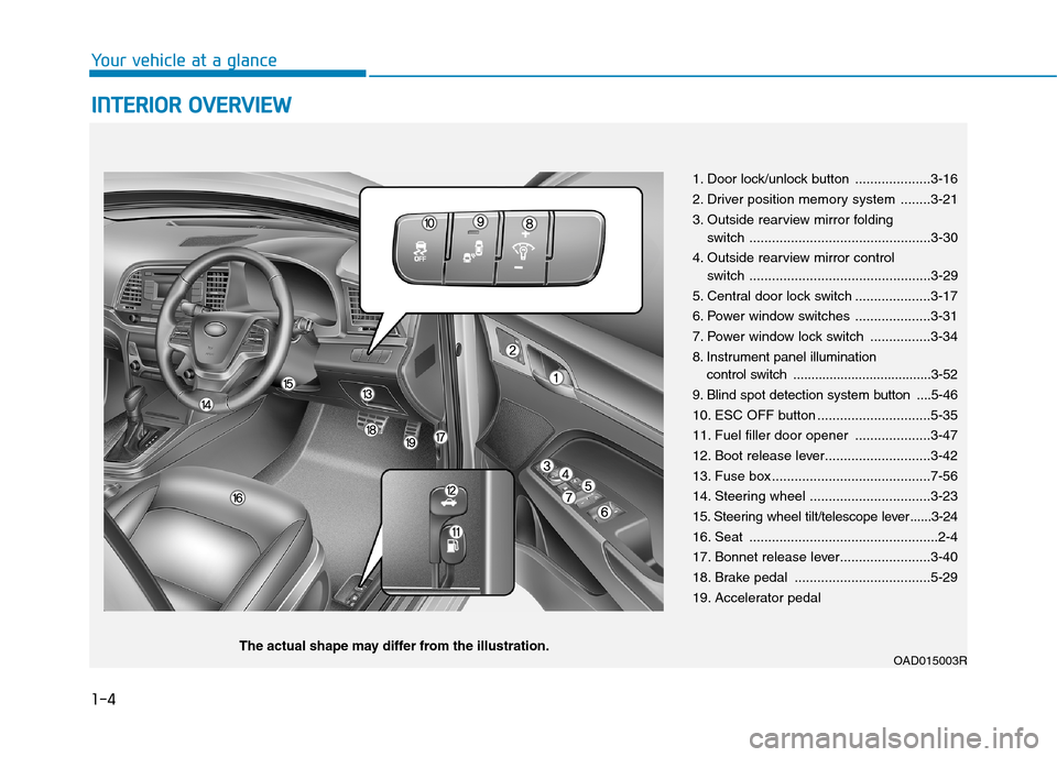
1. Door lock/unlock button ....................3-16
2. Driver position memory system ........3-21
3. Outside rearview mirror folding
switch ................................................3-30
4. Outside rearview mirror control
switch ................................................3-29
5. Central door lock switch ....................3-17
6. Power window switches ....................3-31
7. Power window lock switch ................3-34
8. Instrument panel illumination
control switch ......................................3-52
9. Blind spot detection system button ....5-46
10. ESC OFF button ..............................5-35
11. Fuel filler door opener ....................3-47
12. Boot release lever............................3-42
13. Fuse box ..........................................7-56
14. Steering wheel ................................3-23
15. Steering wheel tilt/telescope lever ......3-24
16. Seat ..................................................2-4
17. Bonnet release lever........................3-40
18. Brake pedal ....................................5-29
19. Accelerator pedal
OAD015003RThe actual shape may differ from the illustration.
Page 27 of 571
EENNGGIINNEE CCOOMMPPAARRTTMMEENNTT
1-6
Yo u r v e h i c l e a t a g l a n c e
OAD075100R
■■Petrol Engine (Nu 2.0 MPI)
1. Engine coolant reservoir....................7-22
2. Radiator cap ......................................7-21
3. Brake/clutchfluid reservoir ..............7-24
4. Air cleaner ........................................7-28
5. Engine oil dipstick..............................7-19
6. Engine oil filler cap ............................7-20
7. Windscreen washer fluid reservoir ....7-26
8. Fuse box ............................................7-50
9. Battery ..............................................7-34
The actual engine compartment in the vehicle may differ from the illustration.
Page 169 of 571
3-77
Convenient features of your vehicle
3
Tu r n o n F U S E S W I T C H
This warning message is displayed if
the fuse switch located on the fuse
box under the steering wheel is OFF.
Yo u s h o u l d t u r n t h e f u s e s w i t c h o n .
For more details, refer to “Fuses”
in chapter 7.
Align steering wheel
(if equipped)
This warning message is displayed if
you star t the engine when the steer-
ing wheel is turned to more than 90
degrees to the left or right.
In order to align the steering wheel,
turn the wheel in the direction shown
whilst the engine is running, to
straighten the steering wheel.
Steering wheel aligning is com-
pleted (if equipped)
If the steering wheel aligning is com-
pleted after "Align steering wheel"
warning message is displayed, this
message is displayed for 2 seconds.
OTL045156L/OTL045157L
■Supervision cluster
OAD045144/OTL045155L
■Conventional cluster ■Supervision cluster
OTL045158L
■Supervision cluster
Page 473 of 571
7-3
7
Maintenance
EENNGGIINNEE CCOOMMPPAARRTTMMEENNTT
OAD075100R
■■Petrol Engine (Nu 2.0 MPI)
The actual engine compartment in the vehicle may differ from the illustration.
1. Engine coolant reservoir
2. Radiator cap
3. Brake/clutch fluid reservoir
4. Air cleaner
5. Engine oil dipstick
6. Engine oil filler cap
7. Windscreen washer fluid reservoir
8. Fuse box
9. Battery
Page 524 of 571
7-54
Maintenance
Engine compartment panel fuse
replacement
1. Turn the engine off.
2. Turn all the switches off.
3. Remove the fuse box cover by
pressing the tab and pulling up.
4. Check the removed fuse; replace it
if it is blown. To remove or insert
the fuse, use the fuse puller in the
engine compartment fuse panel.
5. Push in a new fuse of the same
rating, and make sure it fits tightly
in the clips. If it fits loosely, we rec-
ommend that you consult an
authorised HYUNDAI dealer.
After checking the fuse box in the
engine compartment, securely
install the fuse box cover. If not,
electrical failures may occur from
water leaking in.
Main fuse
If an electrical system does not oper-
ate with no blown fuse in the engine
compartment and inner fuse box, the
main fuse inside the battery (+) cap
may be blown.
The main fuse is heavily connected
to many other parts. In this case, we
recommend you to contact an autho-
rised HYUNDAI dealer.
NOTICE
OAD075025
OAD075024
Page 525 of 571

7-55
7
Maintenance
Multi fuse
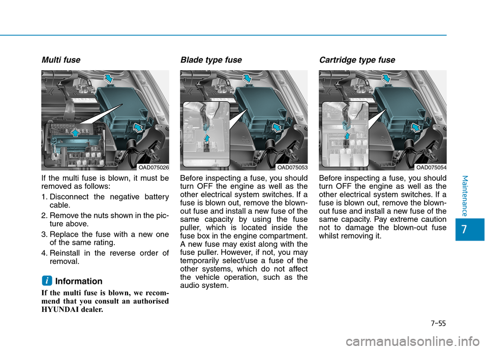
If the multi fuse is blown, it must be
removed as follows:
1. Disconnect the negative battery
cable.
2. Remove the nuts shown in the pic-
ture above.
3. Replace the fuse with a new one
of the same rating.
4. Reinstall in the reverse order of
removal.
Information
If the multi fuse is blown, we recom-
mend that you consult an authorised
HYUNDAI dealer.
Blade type fuse
Before inspecting a fuse, you should
turn OFF the engine as well as the
other electrical system switches. If a
fuse is blown out, remove the blown-
out fuse and install a new fuse of the
same capacity by using the fuse
puller, which is located inside the
fuse box in the engine compartment.
A new fuse may exist along with the
fuse puller. However, if not, you may
temporarily select/use a fuse of the
other systems, which do not affect
the vehicle operation, such as the
audio system.
Cartridge type fuse
Before inspecting a fuse, you should
turn OFF the engine as well as the
other electrical system switches. If a
fuse is blown out, remove the blown-
out fuse and install a new fuse of the
same capacity. Pay extreme caution
not to damage the blown-out fuse
whilst removing it.
i
OAD075026OAD075054OAD075053
Page 526 of 571
7-56
Maintenance
Fuse/Relay panel description
Driver’s side fuse panel
Inside the fuse/relay box covers, you
can find the fuse/relay label describ-
ing fuse/relay names and capacities.
Information
Not all fuse panel descriptions in this
manual may be applicable to your
vehicle. It is accurate at the time of
printing. When you inspect the fuse
box on your vehicle, refer to the fuse
box label.
i
OAD075029R
OAD075064L
Page 528 of 571

7-58
Maintenance
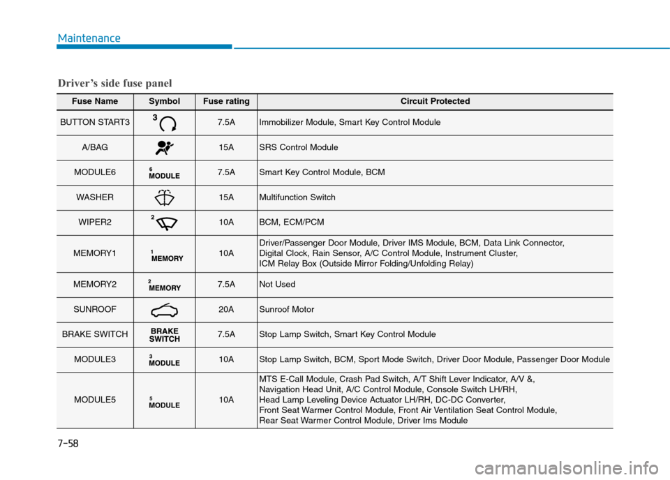
Fuse NameSymbolFuse ratingCircuit Protected
BUTTON START37.5AImmobilizer Module, Smart Key Control Module
A/BAG15ASRS Control Module
MODULE67.5ASmart Key Control Module, BCM
WASHER15AMultifunction Switch
WIPER210ABCM, ECM/PCM
MEMORY110ADriver/Passenger Door Module, Driver IMS Module, BCM, Data Link Connector, Digital Clock, Rain Sensor, A/C Control Module, Instrument Cluster, ICM Relay Box (Outside Mirror Folding/Unfolding Relay)
MEMORY27.5ANot Used
SUNROOF20ASunroof Motor
BRAKE SWITCH7.5AStop Lamp Switch, Smart Key Control Module
MODULE310AStop Lamp Switch, BCM, Sport Mode Switch, Driver Door Module, Passenger Door Module
MODULE5MODULE510A
MTS E-Call Module, Crash Pad Switch, A/T Shift Lever Indicator, A/V &, Navigation Head Unit, A/C Control Module, Console Switch LH/RH,Head Lamp Leveling Device Actuator LH/RH, DC-DC Converter,Front Seat War mer Control Module, Front Air Ventilation Seat Control Module,Rear Seat Warmer Control Module, Driver Ims Module
Driver’s side fuse panel