Page 65 of 85

DRIVING
122 || 123
D
RIVING
Models with touchscreen
1.
From the HOME screen, select Settings.
2.
Select Camera.
3.
Select one of the options.
Fixed Guidelines: Guidelines appear when you
change the gear to Reverse. Select On or Off.
Dynamic Guidelines: Guidelines move as you turn
the steering wheel. Select On or Off.
4.
Press BACK to exit the menu.
The rear camera view is restricted. You cannot see the corner ends of the bumper or what is
underneath the bumper. Its unique lens also makes objects appear closer or farther than they \
actually are.
Visually confirm that it is safe to drive before backing up. Certain c\
onditions (such as weather,
lighting, and high temperatures) may also restrict the rear view. Do not rely on the rearview display,
which does not give you all information about conditions at the rear of \
your vehicle.
Refueling
Use the proper fuel and refueling procedure to ensure the best performan\
ce and safety
of your vehicle.
n
Fuel Information
Use of unleaded gasoline of 87 octane or higher is recommended.
Honda recommends TOP TIER Detergent Gasoline where available.
Do NOT use gasoline containing more than 15% ethanol.
Do NOT use gasoline containing methanol.
Do NOT use gasoline containing MMT.
We recommend quality gasoline containing detergent additives that help pr\
event
fuel system and engine deposits. In addition, in order to maintain good \
performance,
fuel economy, and emissions control, we strongly recommend the use of
gasoline
that does NOT contain harmful manganese-based fuel additives such as MMT\
, if
such gasoline is available.
NOTICE n
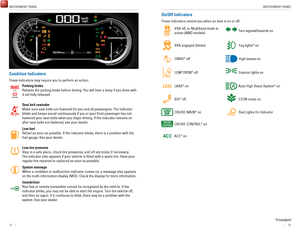
How to Refuel
1.
The fuel fill door is located at the left rear of the
vehicle. Park next to the service pump that is most
accessible.
2.
Turn off the engine.
3.
Press the fuel fill door release button on the
driver’s door. The fuel fill door opens.
4.
Place the end of the filler nozzle on the lower part
of the filler opening, then insert it slowly and fully.
5.
After filling, wait about 5 seconds before removing
the filler nozzle. Close the fuel fill door by hand.
Gasoline is highly flammable and explosive. You can be burned or
seriously injured when handling fuel.
Stop the engine, and keep heat, sparks, and flame away.
Handle fuel only outdoors.
Wipe up spills immediately.
WARNING
NOTICE
The fuel filler opening is designed to accept only service station fi\
ller nozzles for
refueling. Use of smaller diameter tubes (e.g., to siphon fuel for othe\
r uses) or other
non-service station devices can damage the area in and around the fill\
er opening.
NOTICE
Page 66 of 85

DRIVING
124 || 125
H
ANDLING THE UNEXPECTED
n Refueling from a Portable Fuel Container
If you need to refuel your vehicle from a portable fuel container, use the funnel
provided with your vehicle.
1.
Turn off the engine.
2.
Press the fuel fill door release button. The fuel fill
door opens.
3.
Open the in-bed trunk and pull out the tire tray.
4.
Remove the funnel from the tool box.
5.
Place the end of the funnel on the lower part of
filler opening, then insert it slowly and fully. Make
sure that the end of the funnel goes down along
with the filler pipe.
6.
Fill the tank with fuel from the portable fuel
container. Pour fuel carefully so you do not spill
any.
7.
Remove the funnel from the filler neck. Wipe up
any fuel from the funnel before storing it.
8.
Shut the fuel fill door by hand.
Funnel
Funnel
Do not insert the nozzle of a portable fuel container or any funnel othe\
r than the one
provided with your vehicle. Doing so can damage the fuel system.
Do not try to pry open or push open the sealed fuel tank with foreign ob\
jects.
This can damage the fuel system and its seal.
NOTICE
HANDLING THE UNEXPECTED
Learn about what to do in critical or emergency situations.
Smart Entry Remote Battery Strength
If the battery life in your remote transmitter is weak, a message appear\
s in the MID with
information on how to start the engine.
1.
Touch the back of the remote transmitter to the
ENGINE START/STOP button while the indicator
is flashing.
2.
With the brake pedal pressed, press the ENGINE
START/STOP button within 10 seconds.
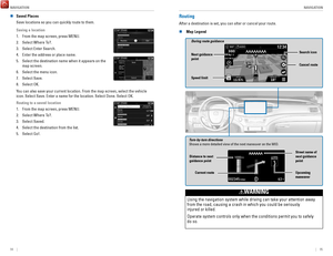
Shift Lever Does Not Move
Follow the procedure below if you cannot move the shift lever out of Par\
k (P).
1.
Set the parking brake.
2.
Remove the built-in key from the remote transmitter.
3.
Open the lid of the console compartment.
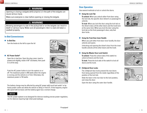
4.
Wrap a cloth around the tip of a small flat-tip
screwdriver. Put it into the shift lock release slot as
shown in the image, and remove the cover.
5.
Insert the key into the shift lock release slot.
6.
While pushing the key down, press the shift lever
release button and place the shift lever into Neutral
(N). The lock is now released. Have the shift lever
checked by a dealer as soon as possible.
Cover
Release
button
Shift lock
release slot
Page 67 of 85

HANDLING THE UNEXPECTED
126 || 127
H
ANDLING THE UNEXPECTED
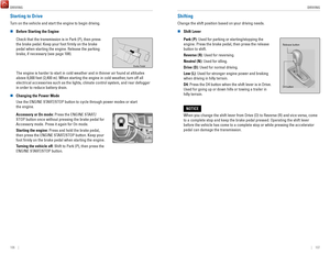
Jump Starting
Turn off the power to electric devices, such as audio and lights. Turn off the engine, then
open the hood.
1.
Remove the engine compartment cover
(see page 141).
2.
Remove the holding clips and the air intake duct.
3.
Connect the first jumper cable to your vehicle’s battery
(+) terminal.
4.
Connect the other end of the first jumper cable to the
booster battery (+) terminal. Use a 12-volt booster
battery only.
5.
Connect the second jumper cable to the booster
battery (-) terminal.
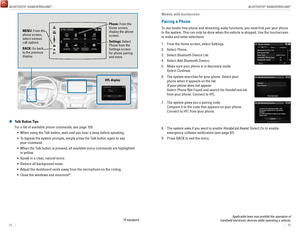
6.
Connect the other end of the second jumper cable
to the engine hanger as shown. Do not connect this
jumper cable to any other part.
7.
If your vehicle is connected to another vehicle, start
the assisting vehicle’s engine and increase its rpm
slightly.
8.
Attempt to start your vehicle’s engine. If it turns over
slowly, make sure that the jumper cables have good
metal-to-metal contact.
Clip
Air intake duct
Engine cover
Pins
WARNING: Battery posts, terminals, and related accessories contain lead and lead\
compounds. Wash your hands after handling.
A battery can explode if you do not follow the correct procedure, seriou\
sly
injuring anyone nearby.
Keep all sparks, open flames, and smoking materials away from the batt\
ery.
WARNING
n After the Engine Starts
Once your vehicle’s engine has started, remove the jumper cables in the
following order:
1.
Disconnect the jumper cable from the engine hanger.
2.
Disconnect the other end of the jumper cable from the booster
battery’s (-) terminal.
3.
Disconnect the jumper cable from the booster battery’s (+) terminal.
4.
Disconnect the other end of the jumper cable from your vehicle’s (+) terminal.
5.
Have your vehicle inspected by a nearby service station or a dealer.
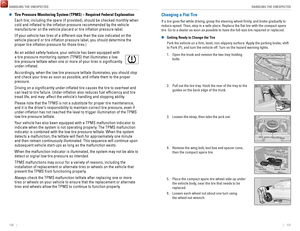
Overheating
If the temperature gauge needle is at the H mark, the engine suddenly lo\
ses power, or
steam or spray comes out from under the hood, your engine is overheating\
.
1.
Immediately park the vehicle in a safe place. Turn off
all accessories and turn on the hazard warning lights.
2.
If steam or spray is not present: Keep the engine
running and open the hood.
If steam or spray is present: Turn off the engine and
wait until it subsides. Then, open the hood.
Reserve tank
MIN MAX
3. Check that the cooling fan is operating and stop the engine once the tem\
perature
gauge needle comes down. If the cooling fan is not operating, immediatel\
y stop
the engine.
4.
Once the engine has cooled down, inspect the coolant level and check the\
cooling
system components for leaks. If the coolant level in the reserve tank is\
low, add
coolant until it reaches the MAX mark. If there is no coolant in the res\
erve tank,
make sure the radiator is cool, then cover the radiator cap with a heavy\
cloth and
open the cap. If necessary
, add coolant up to the base of the filler neck, and put the
cap back on.
Once the engine has cooled sufficiently, restart it and check the temperature gauge.
If the temperature needle has gone down, resume driving. If it has not g\
one down,
contact a dealer for repairs.
Steam and spray from an overheated engine can seriously scald you.
Do not open the hood if steam is coming out.
WARNING
Removing the radiator cap while the engine is hot can cause the coolant \
to
spray out, seriously scalding you.
Always let the engine and radiator cool down before removing the radiato\
r
cap.
WARNING
Continuing to drive with the temperature gauge needle at the H mark may \
damage
the engine.
NOTICE
Page 68 of 85

HANDLING THE UNEXPECTED
128 || 129
H
ANDLING THE UNEXPECTED
Emergency Engine Stop
The ENGINE START/STOP button may be used to stop the engine due to an emergency
situation even while driving. If you must stop the engine, choose one of\
the following
operations:
•
Press and hold the ENGINE START/STOP button
for two seconds, or
•
Firmly press the ENGINE START/STOP button
three times.
If the vehicle is in Park (P), the power mode changes to VEHICLE OFF. Otherwise, the
power mode changes to ACCESSORY.
The steering wheel will not lock. Because turning off the engine also di\
sables the
power assist the engine provides to the steering and braking systems, it\
will require
significantly more physical effort and time to steer and slow the vehi\
cle. Use both feet
on the brake pedal, if necessary, to slow the vehicle and stop immediately in
a safe place.
Do not press the button while driving unless it is absolutely necessary \
for the engine to
be switched off.
Emergency Towing
Call a professional towing service if you need to tow your vehicle.
All models
Flat bed equipment: The operator loads your vehicle on the back of a tru\
ck.
This is the best way to transport your vehicle.
2WD models
Wheel lift equipment: The tow truck uses two pivoting arms that go under the front tires
and lift them off the ground. The rear tires remain on the ground.
This is an acceptable way to tow your vehicle.
Trying to lift or tow your vehicle by the bumpers will cause serious dama\
ge.
The bumpers are not designed to support the vehicle’s weight.
Improper towing such as towing behind a motorhome or other motor vehicle\
can
damage the transmission.
NOTICE
Tire Pressure Monitoring System (TPMS)
Monitors the tire pressure while you are driving.
If your vehicle’s tire pressure becomes significantly low,
the low tire pressure indicator comes on and a message
appears on the multi-information display. The specific tire
with low pressure is displayed.
n What to Do
Stop your vehicle in a safe place. Check the tire pressure and adjust th\
e pressure to
the specified level. The specified tire pressure is on a label on th\
e driver’s doorjamb.
n
Tire Fill Assist
Your vehicle gives you visual and audible alerts to help you adjust the t\
ire pressure to its appropriate level when the vehicle is on.
While inflating: The system beeps and the exterior lights flash once every 5 seconds.
When the correct pressure is reached:
The system beeps and the exterior lights
flash continuously for 5 seconds. Stop filling the tire.
If you overinflate: The system beeps and the exterior lights flash twice every
3 seconds.
Driving on an extremely underinflated tire can cause it to overheat. A\
n overheated
tire can fail. Always inflate your tires to the specified pressure.
NOTICE
Page 69 of 85
 – Required Federal Explanatio\
n
Each tire, including the spare (if provided), should be ch")
HANDLING THE UNEXPECTED
130 || 131
H
ANDLING THE UNEXPECTED
n Tire Pressure Monitoring System (TPMS) – Required Federal Explanatio\
n
Each tire, including the spare (if provided), should be checked monthl\
y when
cold and inflated to the inflation pressure recommended by the vehic\
le
manufacturer on the vehicle placard or tire inflation pressure label.
(If your vehicle has tires of a different size than the size indicated \
on the
vehicle placard or tire inflation pressure label, you should determine\
the
proper tire inflation pressure for those tires.)
As an added safety feature, your vehicle has been equipped with
a tire pressure monitoring system (TPMS) that illuminates a low
tire pressure telltale when one or more of your tires is significantly\
under-inflated.
Accordingly, when the low tire pressure telltale illuminates, you should stop
and check your tires as soon as possible, and inflate them to the prop\
er
pressure.
Driving on a significantly under-inflated tire causes the tire to overheat and
can lead to tire failure. Under-inflation also reduces fuel efficiency and tire
tread life, and may affect the vehicle’s handling and stopping ability.
Please note that the TPMS is not a substitute for proper tire maintenanc\
e,
and it is the driver’s responsibility to maintain correct tire pressure, even if
under-inflation has not reached the level to trigger illumination of the TP\
MS
low tire pressure telltale.
Your vehicle has also been equipped with a TPMS malfunction indicator to \
indicate when the system is not operating properly. The TPMS malfunction
indicator is combined with the low tire pressure telltale. When the syst\
em
detects a malfunction, the telltale will flash for approximately one m\
inute
and then remain continuously illuminated. This sequence will continue up\
on
subsequent vehicle start-ups as long as the malfunction exists.
When the malfunction indicator is illuminated, the system may not be abl\
e to
detect or signal low tire pressure as intended.
TPMS malfunctions may occur for a variety of reasons, including the
installation of replacement or alternate tires or wheels on the vehicle \
that
prevent the TPMS from functioning properly.
Always check the TPMS malfunction telltale after replacing one or more
tires or wheels on your vehicle to ensure that the replacement or altern\
ate
tires and wheels allow the TPMS to continue to function properly.
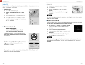
Changing a Flat Tire
If a tire goes flat while driving, grasp the steering wheel firmly, and brake gradually to
reduce speed. Then, stop in a safe place. Replace the flat tire with t\
he compact spare
tire. Go to a dealer as soon as possible to have the full-size tire repa\
ired or replaced.
n
Getting Ready to Change the Tire
Park the vehicle on a firm, level, non-slippery surface. Apply the par\
king brake, shift
to Park (P), and turn the vehicle off. Turn on the hazard warning lights.
1.
Open the trunk and remove the two tray-holding
bolts.
Tire Tray
Tire Tray Holding Bolts
2. Pull out the tire tray. Hook the rear of the tray to the
guides on the back edge of the trunk.
Handle s
3. Loosen the strap, then take the jack out.
StrapJack
4. Remove the wing bolt, tool box and spacer cone,
then the compact spare tire.Wing Bol t
Spacer ConeTool Box
5. Place the compact spare tire wheel-side up under
the vehicle body, near the tire that needs to be
replaced.
6.
Loosen each wheel nut about one turn using
the wheel nut wrench.
Page 70 of 85

HANDLING THE UNEXPECTED
132 || 133
H
ANDLING THE UNEXPECTED
n Setting Up the Jack
1.
Place the jack under the jacking point closest to
the tire to be changed.
2. Turn the end bracket clockwise (as shown in the
image) until the top of the jack contacts the jacking
point. Make sure that the jacking point tab is
resting in the jack notch.
3. Raise the vehicle, using the jack handle bar and the
jack handle, until the tire is off the ground.
Jack handle bar
Wheel nut wrench as jack handle
The vehicle can easily roll off the jack, seriously injuring anyone
underneath.
Follow the directions for changing a tire exactly, and never get under the
vehicle when it is supported only by the jack.
WARNING
Do not use the jack if it doesn’t work properly. Call your dealer or a professional
towing service.
NOTICE
The following instructions must be followed to use the jack safely: •
Do not use the jack with people or luggage in the vehicle.
•
Use the jack provided in your vehicle. Other jacks may not support the w\
eight (load) or fit the jacking point.
•
Do not use while the engine is running.
•
Use only where the ground is firm and level.
•
Use only at the jacking points.
•
Do not get in the vehicle while using the jack.
•
Do not put anything on top of or underneath the jack. n
Replacing the Flat Tire
1.
Remove the wheel nuts and flat tire.
2.
Mount the compact spare tire. Replace the wheel
nuts, and lightly tighten them.
3.
Lower the vehicle and remove the jack. Tighten the
wheel nuts in the order indicated in the image. Go
around, tightening the nuts, two to three times in
this order. Do not overtighten the wheel nuts.
If you drive with the spare tire installed, the low tire
pressure/TPMS indicator appears. The indicator
stays on until a regular tire is installed.
n Storing the Flat Tire
1.
Remove the cap using a cloth-wrapped, flat-tipped
screwdriver.Cap
2. Place the spacer cone on the flat tire’s wheel
center, then mount the wheel using the wing bolt.
3.
Store the jack in the tire tray using the strap. Close
the tire tray and tighten the holding bolts.
4.
Store the center cap and tool kit in the in-bed trunkWing BoltSpacer Cone
Loose items can fly around the interior in a crash and can seriously i\
njure
the occupants.
Store the wheel, jack, and tools securely before driving.
WARNING
Page 71 of 85

HANDLING THE UNEXPECTED
134 || 135
H
ANDLING THE UNEXPECTED
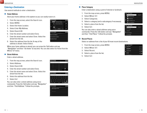
Fuse Locations
If any electrical devices are not working, turn the vehicle off and chec\
k to see if any
applicable fuse is blown. Fuse locations are shown on the fuse box cover\
. Locate the
fuse in question by the fuse number and box cover number.
n
Engine Compartment Fuse Box A
Located under the hood on the passenger’s side.
Push the tabs to open the box.
Tab
Circuit ProtectedAmps
1
�(70 A)*1AC INVERTER70
A*2RR BLOWER30 A*1�(30 A)*2VSA MTR40 A
VSA FSR20 AMAIN FAN30 A*1�(30 A)*2MAIN FUSE 150 A
2
SUB FAN30 A
WIP MTR30 AWASHER20 A
�(20 A)�(30 A)FR BLOWER 40 AAUDIO AMP(30 A)
RR DEF30 A*1�(30 A)*2�(40 A)
�(30 A)*1RR DEF30 A*2�(20 A)
3
��*1RR BLOWER30 A*2��*1�(30 A)*2��*1�(30 A)*2��*1MAIN FAN
4 SMALL 30
A
*2
STOP 10
A*110 A*25��
6 STOP
SMALL 10
A*110 A*27��
8 L H/L LO
10 A*1IGPS9 7.5
A*2��
10 R H/L LO
10 A*1L H/L LO
11 10
A
*2IGPS7.5 A*1R H/L LO
12 10
A
*2INJECTO R2 0 A*1IG COIL15 A*2
13H/L LO MAIN20 A*1DBW14 15
A*2USB15 A
AmpsCircuit Protecte d
15
*1:Models without the AC power outlet
*2:Models with the AC power outle t
(15 A)*1
16 10
A
*215 A*115 A*217(20 A)
18(20 A)
1920 A
20 7.5 A
2115 A*1
22 15
A*215 A
2315 A*120 A*2
24 15
A*120 A*22520 A
26 10
A*115 A*22728 (10 A)10
A
2920 A
Circuit Protecte dAmpsFR FOG
BACK UP HAZARD
MAIN RL Y
AS P/SEAT (REC) AS P/SEAT (SLI) ACM
MG CLUTCH MAIN RL Y
HAZARD FI SUB
IG COIL
INJECTOR DBW
H/L LO MAIN
SMALL/STOP MAIN BACK UPFR FOG
H/STEERING WHEEL HORN
RADIO
n Engine Compartment Fuse Box B
Located under the hood near the brake fluid
reservoir. Push the tabs to open the box.
Circuit Protected Amps
1
ST CUT140 A4WD (20 A)IG MAIN30 AIG MAIN230 A
��F/B MAIN 260 AF/B MAIN60 A
EPS60 A
2��3TRL E-BRAKE(20 A)
4 7.5 A
BM S
5H/L HI MAIN6 20
A(7.5 A)
7
8 (7.5 A)
20 A9(20 A)
10 10 A
11TRL CHARGE
+B TRL HAZARD
+B TRL BACKUP
CTR ACC SOCKE T
TRAILER SMAL L
ACC/IG2_MAIN (20 A)
12��13��14��15FR DE-ICER(15 A)16RR _HTD SEAT(20 A)17STRLD7.5 A
Tab
n Interior Fuse Box
Located under the dashboard.
AmpsCircuit Protected
120 A
220 A
37.5 A
420 A
520 A620 A715 A
87.5 A
97.5 A
1010 A
1120 A
12(20 A)
1320 A
1420 A
15(20 A)
167.5 A
17(20 A)
187.5 A
19DR REAR DOOR UNLOCK10 A
2010 A
21
DR P/W
DOOR LOCK SMAR T
AS P/W
FR ACC SOCKET FUEL PUMP ACG
FRONT WIPER ABS/VSA SRS
REAR LEFT P/W BACK P/W
REAR RIGHT P/ W
S/R FUEL LID
DR P/SEAT (REC) CARGO LT
FR SEAT HEATER INTR LT
7.5 A
227.5 A
237.5 A
247.5 A
257.5 A
AS SIDE DOOR UNLOCK
DRL
KEY LOCK A/C
IG1a FEED BACK
INST PANEL LIGHTS
26(7.5 A)277.5 A2810 A297.5 A30�317.5 A327.5 A3310 A3410 A3510 A36(20 A)3710 A3810 A397.5 A407.5 A4110 A42�
Circuit ProtectedAmpsLUMBAR SUPPORT
PARKING LIGHTS OPTIONMETER �
MISS SOL SRS
AS SIDE DOOR LOCK DR DOOR LOCK
DR DOOR UNLOCK DR P/SEAT (SLIDE) RIGHT H/L HILEFT H/L HI
IG1b FEED BACK ACC
DR REAR DOOR LOCK �
Fuse label Fuse box
Page 72 of 85

HANDLING THE UNEXPECTED
136 || 137
M
AINTENANCE
n Inspecting and Changing Fuses
1.
Turn the vehicle off, including all lights and
accessories.
2.
Remove the fuse box cover.
3.
Check the large fuse in the engine compartment.
4.
If the fuse is blown, use a Phillips-head
screwdriver to remove the screws and replace the
fuse with a new one. Reinstall the screws.
5.
Inspect the small fuses in the engine compartment
and the vehicle interior.
6.
If there is a burned out fuse, remove it with the fuse
puller and replace it with a new one.
Fuse puller
Blown fuse
Combined
fuse
Replacing a fuse with one that has a higher rating greatly increases the\
chances of
damaging the electrical system.
NOTICE
MAINTENANCE
Learn about basic maintenance that you can perform on the vehicle yourse\
lf, as well as
information about how to best maintain the vehicle.
Safety Precautions
Some of the most important safety precautions are listed below; however, we cannot
warn you of every conceivable hazard that can arise in performing mainte\
nance. Only
you can decide whether or not you should perform a given task.
n
Maintenance Safety •
To reduce the possibility of fire or explosion, keep cigarettes, sparks\
, and flames away from the battery and all fuel-related parts.
•
Never leave rags, towels, or other flammable objects under the hood.
•
To clean parts, use a commercially available degreaser or parts cleaner, not gasoline.
•
Wear eye protection and protective clothing when working with the battery\
or
compressed air.
•
Do not run the engine in confined spaces where carbon monoxide gas can\
accumulate.
n
Vehicle Safety •
The vehicle must be stationary, and parked on level ground with the parking
brake set and the engine off.
•
Be aware that hot parts can burn you.
•
Be aware that moving parts can injure you.
Improperly maintaining this vehicle or failing to correct a problem befo\
re
driving can cause a crash in which you can be seriously hurt or killed. \
Always follow the inspection and maintenance recommendations
according to the schedules in this guide.
WARNING
Failure to properly follow maintenance instructions and precautions can \
cause you to be seriously hurt or killed.
Always follow the procedures and precautions in this guide.
WARNING
*if equipped