2017 HONDA CLARITY ELECTRIC warning light
[x] Cancel search: warning lightPage 375 of 543
373
uuWhen Driving uAdaptive Cruise Control (ACC) with Low Speed Follow (LSF)
Continued
Driving
Adaptive Cruise Control (ACC) with Low Speed
Follow (LSF)
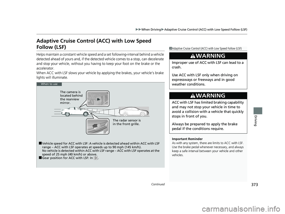
Helps maintain a constant vehicle speed an d a set following-interval behind a vehicle
detected ahead of yours and, if the detect ed vehicle comes to a stop, can decelerate
and stop your ve hicle, without yo u having to keep your foot on the brake or the
accelerator.
When ACC with LSF slows your vehicle by applying the brakes, your vehicle's brake
lights will illuminate.
1 Adaptive Cruise Control (ACC) with Low Speed Follow (LSF)
Important Reminder
As with any system, there are limits to ACC with LSF.
Use the brake pedal whenever necessary, and always
keep a safe interval between your vehicle and other
vehicles.
3WARNING
Improper use of ACC wi th LSF can lead to a
crash.
Use ACC with LSF only when driving on
expressways or freeways and in good
weather conditions.
3WARNING
ACC with LSF has limited braking capability
and may not stop your vehicle in time to
avoid a collision with a vehicle that quickly
stops in front of you.
Always be prepared to apply the brake
pedal if the conditions require.
When to use
■Vehicle speed for ACC with LSF: A vehicle is detected ahead within ACC with LSF
range – ACC with LSF operates at speeds up to 90 mph (145 km/h).
No vehicle is detected within ACC with LSF range – ACC with LSF operates at the
speed of 25 mph (40 km/h) or above.
■Gear position for ACC with LSF: In ( D. The radar sensor is
in the front grille.
The camera is
located behind
the rearview
mirror.
17 CLARITY BEV CSS-31TRV6000.book 373 ページ 2017年4月14日 金曜日 午前11
時8分
Page 391 of 543
Continued389
uuWhen Driving uLane Keeping Assist System (LKAS)
Driving
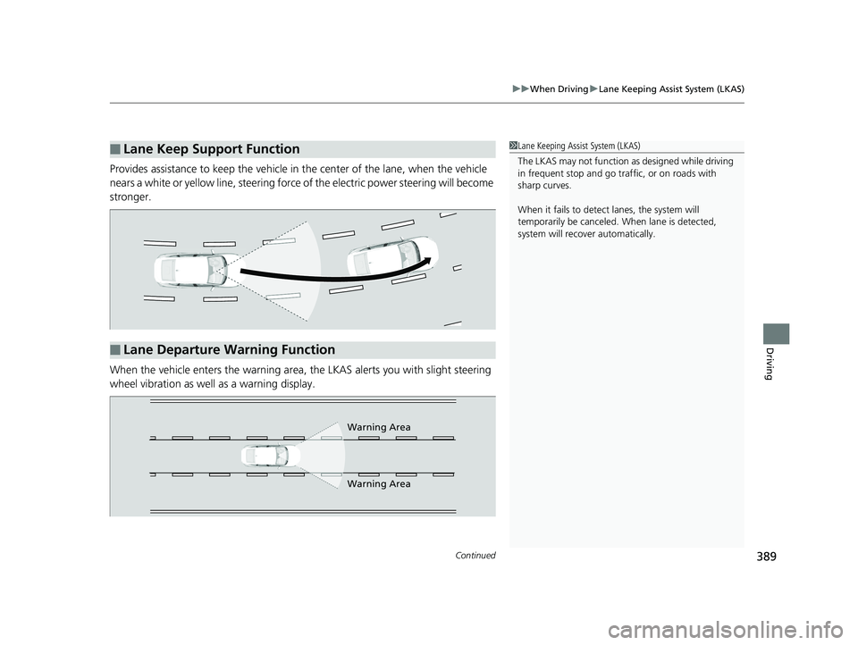
Provides assistance to keep the vehicle in the center of the lane, when the vehicle
nears a white or yellow line, steering force of the electric power steering will become
stronger.
When the vehicle enters the warning area, the LKAS alerts you with slight steering
wheel vibration as well as a warning display.
■Lane Keep Support Function1 Lane Keeping Assist System (LKAS)
The LKAS may not function as designed while driving
in frequent stop and go traf fic, or on roads with
sharp curves.
When it fails to detect lanes, the system will
temporarily be canceled. When lane is detected,
system will recover automatically.
■Lane Departure Warning Function
Warning Area
Warning Area
17 CLARITY BEV CSS-31TRV6000.book 389 ページ 2017年4月14日 金曜日 午前11 時8分
Page 404 of 543
402
uuWhen Driving uLaneWatchTM
Driving
LaneWatchTM
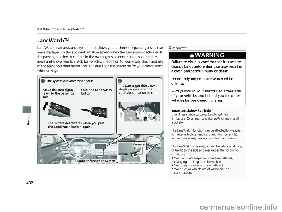
LaneWatch is an assistance system that allows you to check the passenger side rear
areas displayed on the audio/in formation screen when the turn signal is activated to
the passenger’s side. A camera in the passenger side door mirror monitors these
areas and allows you to check for vehicles, in addition to your visual check and use
of the passenger door mirror. You can also keep the system on for your convenience
while driving.1 LaneWatchTM
Important Safety Reminder
Like all assistance systems, LaneWatch has
limitations. Over reliance on LaneWatch may result in
a collision.
The LaneWatch func tion can be affected by weather,
lighting (including headli ghts and low sun angle),
ambient darkness, camera condition, and loading.
The LaneWatch may not prov ide the intended display
of traffic to the side and rear under the following
conditions:
•Your vehicle’s suspension has been altered,
changing the height of the vehicle.
•Your tires are over or under inflated.•Your tires or wheels are of varied size or
construction.
3WARNING
Failure to visually confirm that it is safe to
change lanes before doing so may result in
a crash and serious injury or death.
Do not rely only on LaneWatch while
driving.
Always look in your mirrors, to either side
of your vehicle, and behind you for other
vehicles before changing lanes.
12
Camera
Move the turn signal
lever to the passenger
side.
Press the LaneWatch
button.The passenger side view
display appears on the
audio/information screen.
The system activates when you:
The system deactivates when you press
the LaneWatch button again.
Audio/Information Screen
17 CLARITY BEV CSS-31TRV6000.book 402 ページ 2017年4月14日 金曜日 午前11 時8分
Page 409 of 543
Continued407
uuBraking uBrake System
Driving
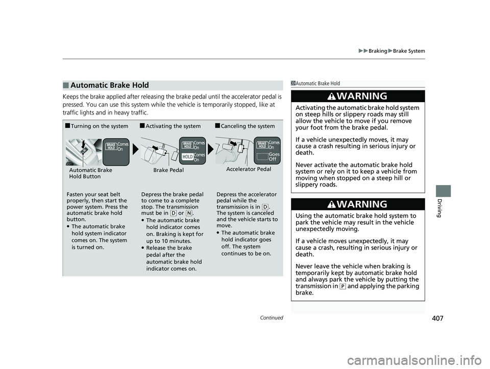
Keeps the brake applied after releasing the brake pedal until the accelerator pedal is
pressed. You can use this system while th e vehicle is temporarily stopped, like at
traffic lights and in heavy traffic.
■Automatic Brake Hold1 Automatic Brake Hold
3WARNING
Activating the automatic brake hold system
on steep hills or slippery roads may still
allow the vehicle to move if you remove
your foot from the brake pedal.
If a vehicle unexpectedly moves, it may
cause a crash resulting in serious injury or
death.
Never activate the automatic brake hold
system or rely on it to keep a vehicle from
moving when stopped on a steep hill or
slippery roads.
3WARNING
Using the automatic brake hold system to
park the vehicle may result in the vehicle
unexpectedly moving.
If a vehicle moves unexpectedly, it may
cause a crash, resulting in serious injury or
death.
Never leave the vehicle when braking is
temporarily kept by automatic brake hold
and always park the vehicle by putting the
transmission in
( P and applying the parking
brake.
■Turning on the system
Fasten your seat belt
properly, then start the
power system. Press the
automatic brake hold
button.
●The automatic brake
hold system indicator
comes on. The system
is turned on.
■Activating the system
Depress the brake pedal
to come to a complete
stop. The transmission
must be in
( D or (N.●The automatic brake
hold indicator comes
on. Braking is kept for
up to 10 minutes.
●Release the brake
pedal after the
automatic brake hold
indicator comes on.
■Canceling the system
Depress the accelerator
pedal while the
transmission is in
( D.
The system is canceled
and the vehicle starts to
move.
●The automatic brake
hold indicator goes
off. The system
continues to be on.
Accelerator PedalBrake PedalAutomatic Brake
Hold Button
Goes
Off
Comes
On Comes
On
Comes
On Comes
On
17 CLARITY BEV CSS-31TRV6000.book 407 ページ 2017年4月14日 金曜日 午前11
時8分
Page 415 of 543
413
uuBraking uCollision Mitigation Braking SystemTM (CMBSTM)
Continued
Driving
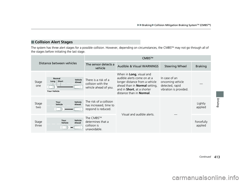
The system has three alert stages for a possible collis ion. However, depending on circumstances, the CMBSTM may not go through all of
the stages before initiating the last stage.
■Collision Alert Stages
Distance between vehicles
CMBSTM
The sensor detects a vehicleAudible & Visual WARNINGSSteering WheelBraking
Stage oneThere is a risk of a
collision with the
vehicle ahead of you.
When in Long, visual and
audible alerts come on at a
longer distance from a vehicle
ahead than in Normal setting,
and in Short, at a shorter
distance than in Normal.
In case of an
oncoming vehicle
detected, rapid
vibration is provided.
—
Stage
twoThe risk of a collision
has increased, time to
respond is reduced.
Visual and audible alerts.—
Lightly
applied
Stage three
The CMBSTM
determines that a
collision is
unavoidable.
Forcefully applied
Your Vehicle Vehicle
Ahead
Short
LongNormal
Your
Vehicle Vehicle
Ahead
Your
VehicleVehicle
Ahead
17 CLARITY BEV CSS-31TRV6000.book 413 ページ 2017年4月14日 金曜日 午前11
時8分
Page 484 of 543
482
Handling the Unexpected
If a Tire Goes Flat
Temporarily Repairing a Flat Tire
If the tire has a large cut or is otherwise severely damaged, you will need to have the
vehicle towed. If the tire only has a smal l puncture, from a nail for instance, you can
use the temporary tire repair kit so that you can drive to the nearest service station
for a more permanent repair.
If a tire goes flat while driving, grasp the steering wheel firmly, and brake gradually
to reduce speed. Then stop in a safe place.
1. Park the vehicle on a firm, level, and non-slippery surface and apply the parking
brake.
2. Change the gear position to
(P.
3. Turn on the hazard warning lights an d set the power mode to VEHICLE OFF
(LOCK).
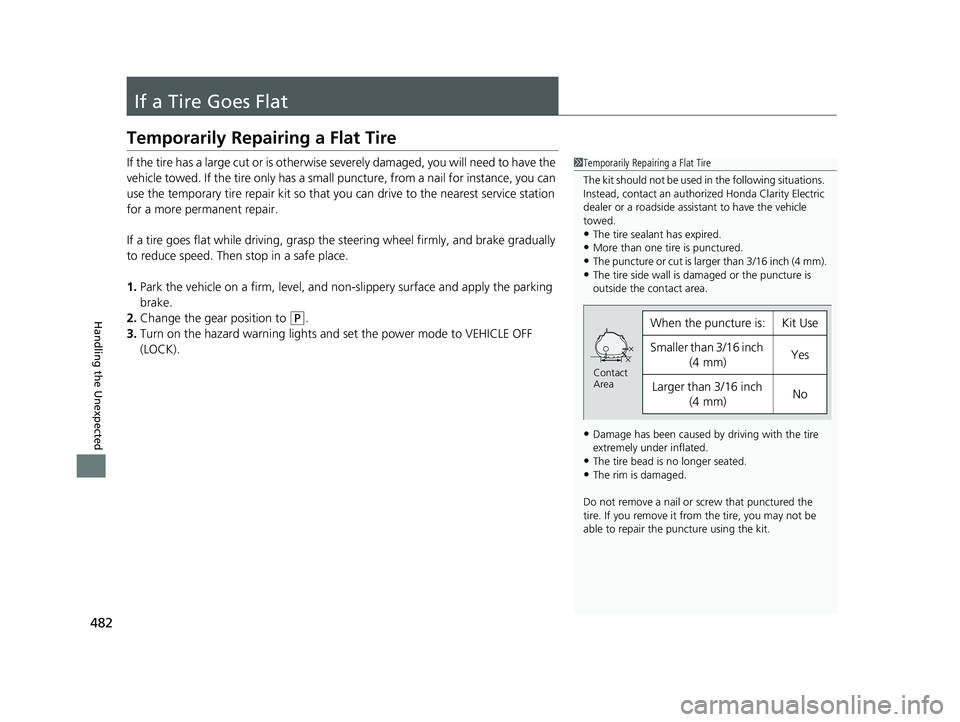
1 Temporarily Repairing a Flat Tire
The kit should not be used in the following situations.
Instead, contact an authorized Honda Clarity Electric
dealer or a roadside assi stant to have the vehicle
towed.
•The tire sealant has expired.•More than one tire is punctured.
•The puncture or cut is larger than 3/16 inch (4 mm).
•The tire side wall is da maged or the puncture is
outside the contact area.
•Damage has been caused by driving with the tire
extremely under inflated.
•The tire bead is no longer seated.•The rim is damaged.
Do not remove a nail or screw that punctured the
tire. If you remove it from the tire, you may not be
able to repair the puncture using the kit.
When the puncture is:Kit Use
Smaller than 3/16 inch (4 mm)Yes
Larger than 3/16 inch
(4 mm)No
Contact
Area
17 CLARITY BEV CSS-31TRV6000.book 482 ページ 2017年4月14日 金曜日 午前11 時8分
Page 497 of 543
495
Handling the Unexpected
Power System Won’t Start
Checking the Procedure
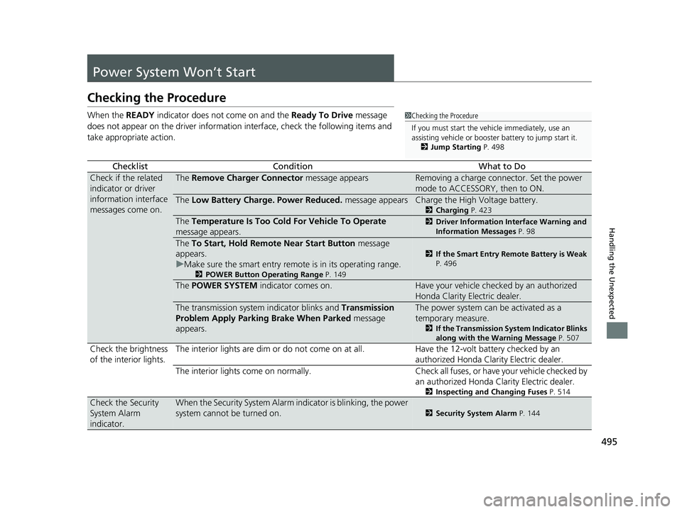
When the READY indicator does not come on and the Ready To Drive message
does not appear on the driver information interface, check the following items and
take appropriate action.
ChecklistConditionWhat to Do
Check if the related
indicator or driver
information interface
messages come on.The Remove Charger Connector message appearsRemoving a charge connector. Set the power
mode to ACCESSORY, then to ON.
The Low Battery Charge . Power Reduced. message appearsCharge the High Voltage battery.
2Charging P. 423
The Temperature Is Too Cold For Vehicle To Operate
message appears.2 Driver Information Interface Warning and
Information Messages P. 98
The To Start, Hold Remote Near Start Button message
appears.
u Make sure the smart entry remote is in its operating range.
2 POWER Button Operating Range P. 149
2If the Smart Entry Remote Battery is Weak
P. 496
The POWER SYSTEM indicator comes on.Have your vehicle checked by an authorized
Honda Clarity Electric dealer.
The transmission system indicator blinks and Transmission
Problem Apply Parking Brake When Parked message
appears.The power system can be activated as a
temporary measure.
2 If the Transmission System Indicator Blinks
along with the Warning Message P. 507
Check the brightness
of the interior lights. The interior lights are dim or do not come on at
all. Have the 12-volt battery checked by an
authorized Honda Clarity Electric dealer.
The interior lights come on normally. Check al l fuses, or have your vehicle checked by
an authorized Honda Clarity Electric dealer.
2 Inspecting and Changing Fuses P. 514
Check the Security
System Alarm
indicator.When the Security System Alarm in dicator is blinking, the power
system cannot be turned on.
2 Security System Alarm P. 144
1Checking the Procedure
If you must start the vehi cle immediately, use an
assisting vehicle or booster battery to jump start it.
2 Jump Starting P. 498
17 CLARITY BEV CSS-31TRV6000.book 495 ページ 2017年4月14日 金曜日 午前11 時8分
Page 500 of 543
498
Handling the Unexpected
Jump Starting
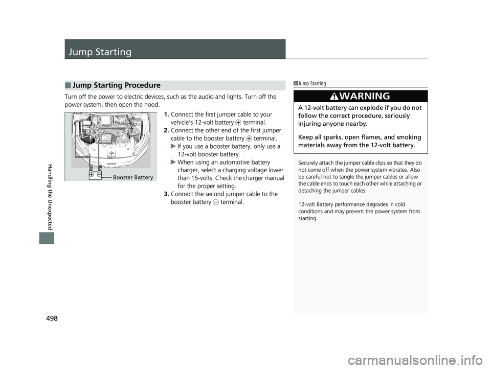
Turn off the power to electric devices, such as the audio and lights. Turn off the
power system, then open the hood.
1.Connect the first jump er cable to your
vehicle’s 12-volt battery + terminal.
2. Connect the other end of the first jumper
cable to the booster battery + terminal.
u If you use a booster battery, only use a
12-volt booster battery.
u When using an automotive battery
charger, select a charging voltage lower
than 15-volts. Check the charger manual
for the proper setting.
3. Connect the second jumper cable to the
booster battery - terminal.
■Jump Starting Procedure1Jump Starting
Securely attach the jumper cable clips so that they do
not come off when the power system vibrates. Also
be careful not to tangle the jumper cables or allow
the cable ends to touch eac h other while attaching or
detaching the jumper cables.
12-volt Battery performa nce degrades in cold
conditions and may prevent the power system from
starting.
3WARNING
A 12-volt battery can explode if you do not
follow the correct procedure, seriously
injuring anyone nearby.
Keep all sparks, open flames, and smoking
materials away from the 12-volt battery.
Booster Battery
17 CLARITY BEV CSS-31TRV6000.book 498 ページ 2017年4月14日 金曜日 午前11 時8分