2017 FORD SUPER DUTY steering
[x] Cancel search: steeringPage 292 of 636
When backing down a ramp during boat
launching or retrieval:
•
Do not allow the static water level to
rise above the bottom edge of the rear
bumper.
• Do not allow waves to break higher
than 6 in (15 cm) above the bottom
edge of the rear bumper.
Exceeding these limits may allow water to
enter vehicle components:
• Causing internal damage to the
components.
• Affecting driveability, emissions, and
reliability.
Replace the rear axle lubricant anytime
the rear axle has been submerged in water.
Water may have contaminated the rear
axle lubricant, which is not normally
checked or changed unless a leak is
suspected or other axle repair is required.
TOWING THE VEHICLE ON
FOUR WHEELS
Emergency Towing
If your vehicle becomes inoperable
(without access to wheel dollies,
car-hauling trailer, or flatbed transport
vehicle), it can be flat-towed (all wheels
on the ground, regardless of the powertrain
and transmission configuration) under the
following conditions:
• Your vehicle is facing forward for
towing in a forward direction.
• Place the transmission in position
N. If
you cannot move the transmission into
N
, you may need to override it. See
Transmission (page 205).
• Maximum speed is 35 mph (56 km/h).
• Maximum distance is
50 mi (80 km). WARNING
If your vehicle has a steering wheel
lock make sure the ignition is in the
accessory or on position when being
towed. Recreational Towing
Note:
Put your climate control system in
recirculated air mode to prevent exhaust
fumes from entering your vehicle. See
Climate Control
(page 145).
Follow these guidelines if you have a need
for recreational towing, such as towing
your vehicle behind a motorhome. We
designed these guidelines to prevent
damage to your transmission.
Two-wheel Drive Vehicles and
Four-wheel Drive Vehicles Equipped
with an Electronic-shift Transfer Case
Do not tow your vehicle with any wheels
on the ground, as vehicle or transmission
damage may occur. It is recommended to
tow your vehicle with all four (4) wheels
off the ground, such as when using a
car-hauling trailer. Otherwise, you cannot
tow your vehicle.
Four-wheel Drive Vehicles Equipped
with a Manual-shift Transfer Case
1. Put the transmission in position
N.
2. Put the transfer case in position
N.
3. Put the hub locks in the FREE position.
Always make sure that both hub locks
are set to the same position.
289
Super Duty (TFE) Canada/United States of America, enUSA, First Printing Towing
Page 294 of 636
•
Fuel economy may decrease with lower
temperatures during the first 8– 10
miles (12 –16 kilometers) of driving.
• Driving on flat terrain offers improved
fuel economy as compared to driving
on hilly terrain.
• Transmissions give their best fuel
economy when operated in the top
cruise gear and with steady pressure
on the gas pedal.
• Four-wheel-drive operation (if
equipped) is less fuel efficient than
two-wheel-drive operation.
• Close the windows for high-speed
driving.
DRIVING THROUGH WATER WARNING
Do not drive through flowing or deep
water as you may lose control of your
vehicle.
Note:
Driving through standing water can
cause vehicle damage.
Note: Engine damage can occur if water
enters the air filter.
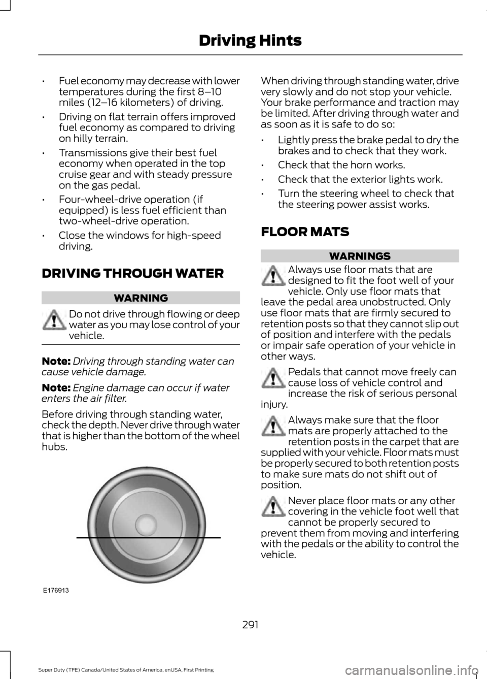
Before driving through standing water,
check the depth. Never drive through water
that is higher than the bottom of the wheel
hubs. When driving through standing water, drive
very slowly and do not stop your vehicle.
Your brake performance and traction may
be limited. After driving through water and
as soon as it is safe to do so:
•
Lightly press the brake pedal to dry the
brakes and to check that they work.
• Check that the horn works.
• Check that the exterior lights work.
• Turn the steering wheel to check that
the steering power assist works.
FLOOR MATS WARNINGS
Always use floor mats that are
designed to fit the foot well of your
vehicle. Only use floor mats that
leave the pedal area unobstructed. Only
use floor mats that are firmly secured to
retention posts so that they cannot slip out
of position and interfere with the pedals
or impair safe operation of your vehicle in
other ways. Pedals that cannot move freely can
cause loss of vehicle control and
increase the risk of serious personal
injury. Always make sure that the floor
mats are properly attached to the
retention posts in the carpet that are
supplied with your vehicle. Floor mats must
be properly secured to both retention posts
to make sure mats do not shift out of
position. Never place floor mats or any other
covering in the vehicle foot well that
cannot be properly secured to
prevent them from moving and interfering
with the pedals or the ability to control the
vehicle.
291
Super Duty (TFE) Canada/United States of America, enUSA, First Printing Driving HintsE176913
Page 295 of 636
WARNINGS
Never place floor mats or any other
covering on top of already installed
floor mats. Floor mats should always
rest on top of vehicle carpeting surface and
not another floor mat or other covering.
Additional floor mats or any other covering
will reduce the pedal clearance and
potentially interfere with pedal operation. Check attachment of floor mats on
a regular basis. Always properly
reinstall and secure floor mats that
have been removed for cleaning or
replacement. Always make sure that objects
cannot fall into the driver foot well
while the vehicle is moving. Objects
that are loose can become trapped under
the pedals causing a loss of vehicle control. Failure to properly follow floor mat
installation or attachment
instructions can potentially cause
interference with pedal operation causing
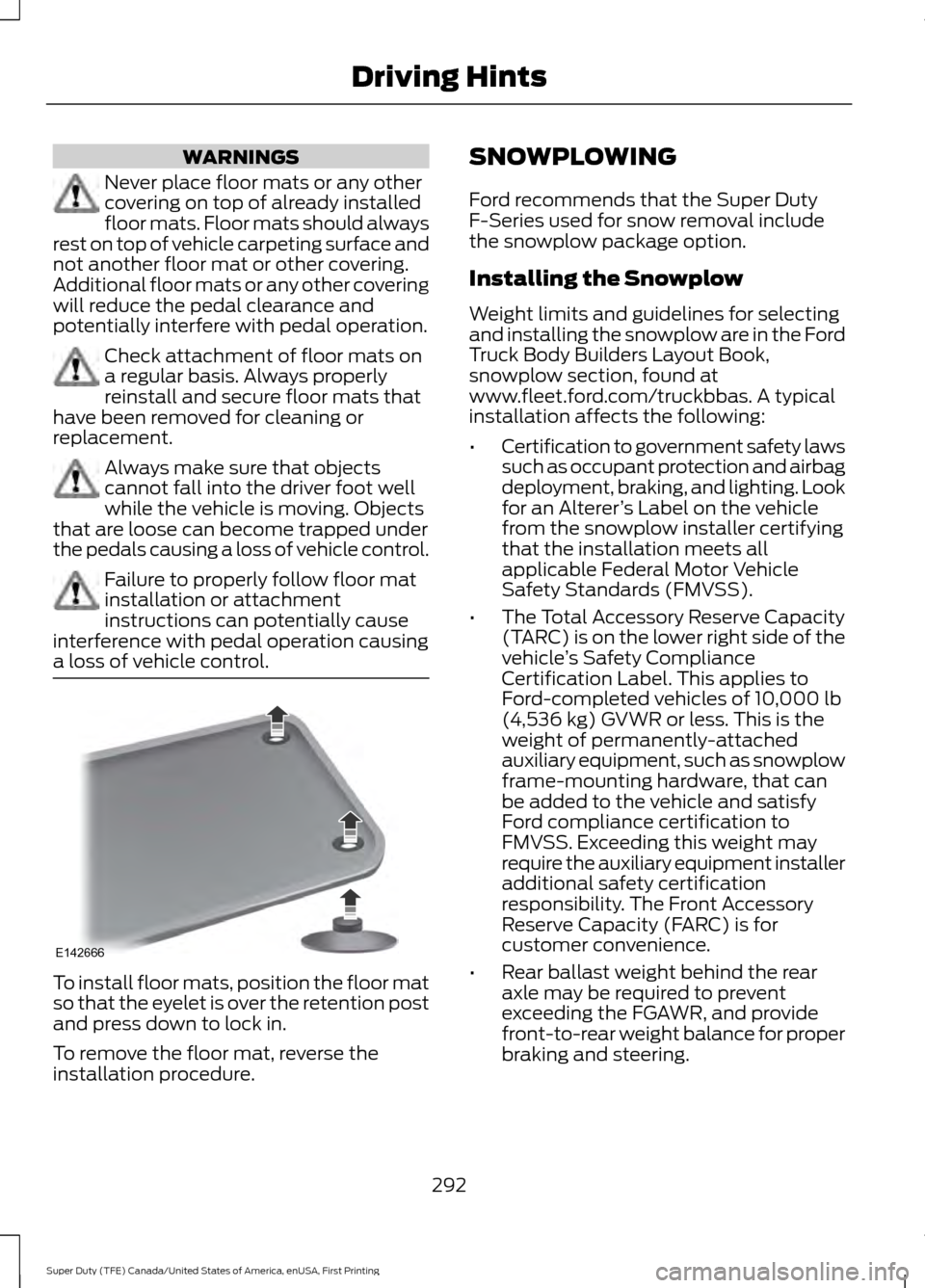
a loss of vehicle control. To install floor mats, position the floor mat
so that the eyelet is over the retention post
and press down to lock in.
To remove the floor mat, reverse the
installation procedure. SNOWPLOWING
Ford recommends that the Super Duty
F-Series used for snow removal include
the snowplow package option.
Installing the Snowplow
Weight limits and guidelines for selecting
and installing the snowplow are in the Ford
Truck Body Builders Layout Book,
snowplow section, found at
www.fleet.ford.com/truckbbas. A typical
installation affects the following:
•
Certification to government safety laws
such as occupant protection and airbag
deployment, braking, and lighting. Look
for an Alterer ’s Label on the vehicle
from the snowplow installer certifying
that the installation meets all
applicable Federal Motor Vehicle
Safety Standards (FMVSS).
• The Total Accessory Reserve Capacity
(TARC) is on the lower right side of the
vehicle ’s Safety Compliance
Certification Label. This applies to
Ford-completed vehicles of 10,000 lb
(4,536 kg) GVWR or less. This is the
weight of permanently-attached
auxiliary equipment, such as snowplow
frame-mounting hardware, that can
be added to the vehicle and satisfy
Ford compliance certification to
FMVSS. Exceeding this weight may
require the auxiliary equipment installer
additional safety certification
responsibility. The Front Accessory
Reserve Capacity (FARC) is for
customer convenience.
• Rear ballast weight behind the rear
axle may be required to prevent
exceeding the FGAWR, and provide
front-to-rear weight balance for proper
braking and steering.
292
Super Duty (TFE) Canada/United States of America, enUSA, First Printing Driving HintsE142666
Page 299 of 636
This program is separate from the New
Vehicle Limited Warranty, but the coverage
is concurrent with the powertrain coverage
period of your vehicle.
Canadian customers who require roadside
assistance, call 1-800-665-2006.
Vehicles Sold in Canada: Using
Roadside Assistance
Complete the roadside assistance
identification card and place it in your
wallet for quick reference.
In Canada, this card is found in the
Warranty Guide in the glove compartment
of your vehicle.
Vehicles Sold in Canada: Roadside
Assistance Program Coverage
The service is available 24 hours a day,
seven days a week.
Canadian roadside coverage and benefits
may differ from the U.S. coverage.
For complete program coverage details
you may contact your dealer, you can call
us in Canada at 1-800-665-2006, or visit
our website at www.ford.ca.
HAZARD WARNING FLASHERS
Note:
The hazard warning flashers will
operate when the ignition is in any position
or if the key is not in the ignition. If used
when the engine is not running, the battery
will lose charge. As a result, there may be
insufficient power to restart your engine. In some models, the hazard
flasher control is located on the
instrument panel.
In other models, this feature is located on
the steering column, just behind the
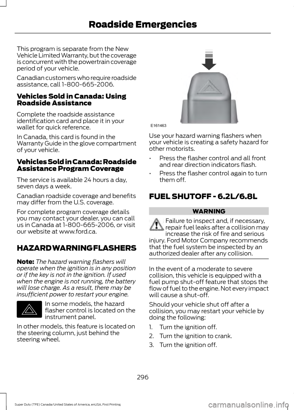
steering wheel. Use your hazard warning flashers when
your vehicle is creating a safety hazard for
other motorists.
•
Press the flasher control and all front
and rear direction indicators flash.
• Press the flasher control again to turn
them off.
FUEL SHUTOFF - 6.2L/6.8L WARNING
Failure to inspect and, if necessary,
repair fuel leaks after a collision may
increase the risk of fire and serious
injury. Ford Motor Company recommends
that the fuel system be inspected by an
authorized dealer after any collision. In the event of a moderate to severe
collision, this vehicle is equipped with a
fuel pump shut-off feature that stops the
flow of fuel to the engine. Not every impact
will cause a shut-off.
Should your vehicle shut off after a
collision, you may restart your vehicle by
doing the following:
1. Turn the ignition off.
2. Turn the ignition to crank.
3. Turn the ignition off.
296
Super Duty (TFE) Canada/United States of America, enUSA, First Printing Roadside EmergenciesE142663 E161463
Page 316 of 636
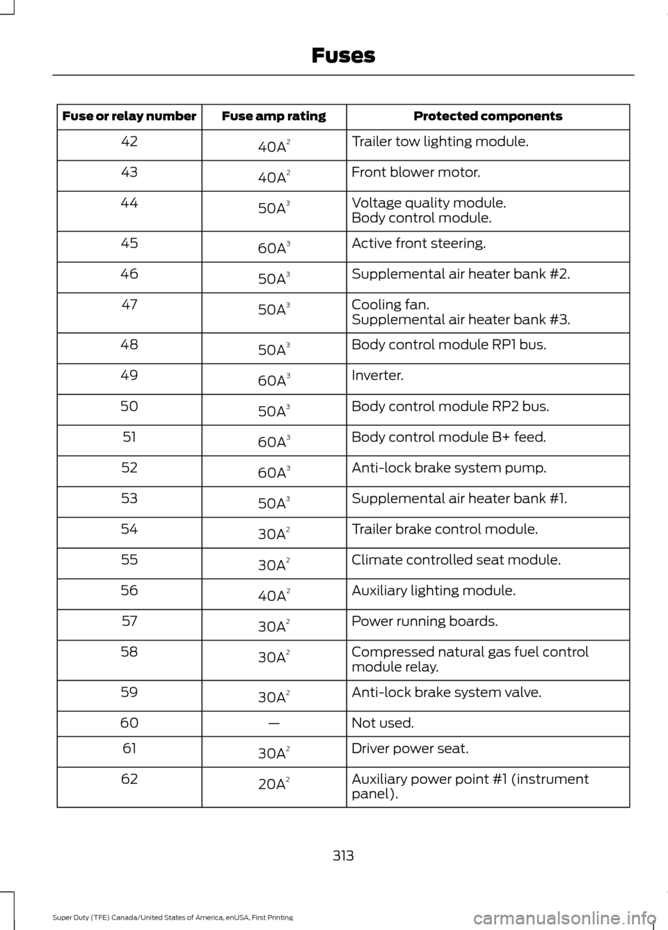
Protected components
Fuse amp rating
Fuse or relay number
Trailer tow lighting module.
40A 2
42
Front blower motor.
40A 2
43
Voltage quality module.
50A 3
44
Body control module.
Active front steering.
60A 3
45
Supplemental air heater bank #2.
50A 3
46
Cooling fan.
50A 3
47
Supplemental air heater bank #3.
Body control module RP1 bus.
50A 3
48
Inverter.
60A 3
49
Body control module RP2 bus.
50A 3
50
Body control module B+ feed.
60A 3
51
Anti-lock brake system pump.
60A 3
52
Supplemental air heater bank #1.
50A 3
53
Trailer brake control module.
30A 2
54
Climate controlled seat module.
30A 2
55
Auxiliary lighting module.
40A 2
56
Power running boards.
30A 2
57
Compressed natural gas fuel control
module relay.
30A
2
58
Anti-lock brake system valve.
30A 2
59
Not used.
—
60
Driver power seat.
30A 2
61
Auxiliary power point #1 (instrument
panel).
20A
2
62
313
Super Duty (TFE) Canada/United States of America, enUSA, First Printing Fuses
Page 318 of 636
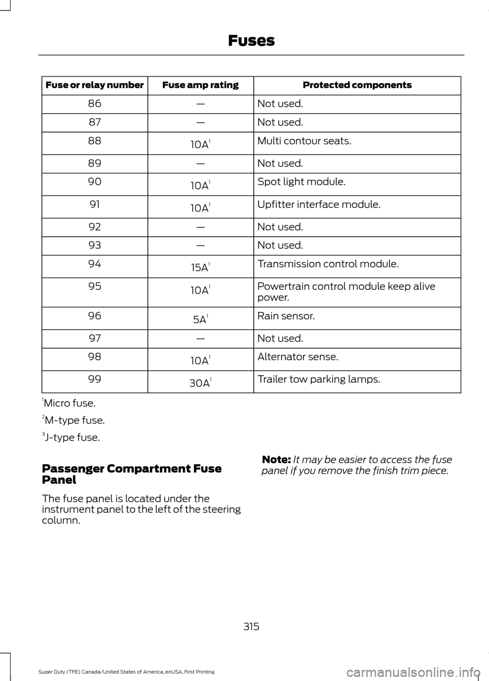
Protected components
Fuse amp rating
Fuse or relay number
Not used.
—
86
Not used.
—
87
Multi contour seats.
10A 1
88
Not used.
—
89
Spot light module.
10A 1
90
Upfitter interface module.
10A 1
91
Not used.
—
92
Not used.
—
93
Transmission control module.
15A 1
94
Powertrain control module keep alive
power.
10A
1
95
Rain sensor.
5A 1
96
Not used.
—
97
Alternator sense.
10A 1
98
Trailer tow parking lamps.
30A 1
99
1 Micro fuse.
2 M-type fuse.
3 J-type fuse.
Passenger Compartment Fuse
Panel
The fuse panel is located under the
instrument panel to the left of the steering
column. Note:
It may be easier to access the fuse
panel if you remove the finish trim piece.
315
Super Duty (TFE) Canada/United States of America, enUSA, First Printing Fuses
Page 320 of 636
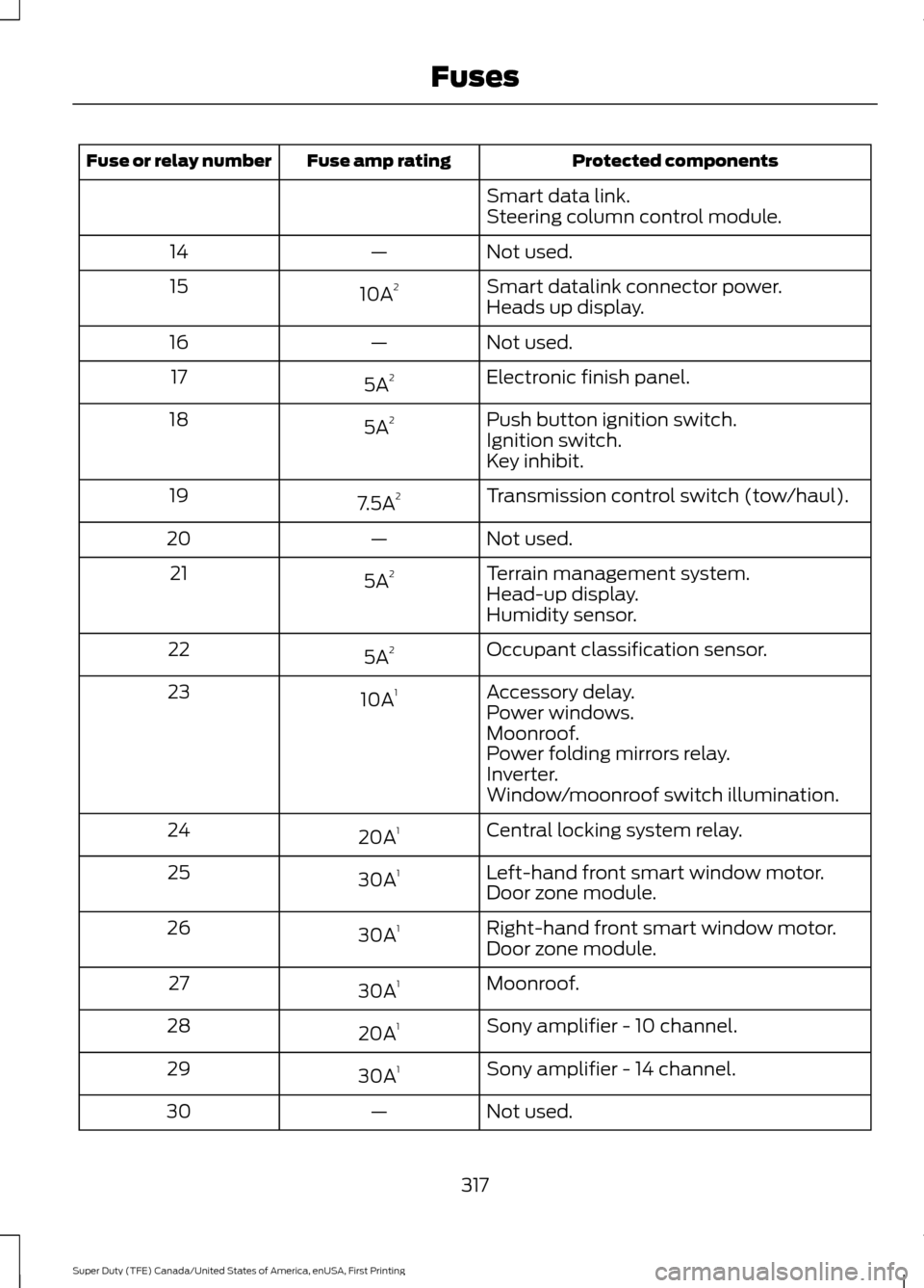
Protected components
Fuse amp rating
Fuse or relay number
Smart data link.
Steering column control module.
Not used.
—
14
Smart datalink connector power.
10A 2
15
Heads up display.
Not used.
—
16
Electronic finish panel.
5A 2
17
Push button ignition switch.
5A 2
18
Ignition switch.
Key inhibit.
Transmission control switch (tow/haul).
7.5A 2
19
Not used.
—
20
Terrain management system.
5A 2
21
Head-up display.
Humidity sensor.
Occupant classification sensor.
5A 2
22
Accessory delay.
10A 1
23
Power windows.
Moonroof.
Power folding mirrors relay.
Inverter.
Window/moonroof switch illumination.
Central locking system relay.
20A 1
24
Left-hand front smart window motor.
30A 1
25
Door zone module.
Right-hand front smart window motor.
30A 1
26
Door zone module.
Moonroof.
30A 1
27
Sony amplifier - 10 channel.
20A 1
28
Sony amplifier - 14 channel.
30A 1
29
Not used.
—
30
317
Super Duty (TFE) Canada/United States of America, enUSA, First Printing Fuses
Page 321 of 636
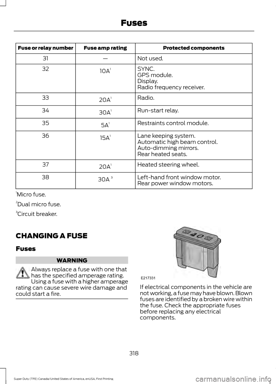
Protected components
Fuse amp rating
Fuse or relay number
Not used.
—
31
SYNC.
10A 1
32
GPS module.
Display.
Radio frequency receiver.
Radio.
20A 1
33
Run-start relay.
30A 1
34
Restraints control module.
5A 1
35
Lane keeping system.
15A 1
36
Automatic high beam control.
Auto-dimming mirrors.
Rear heated seats.
Heated steering wheel.
20A 1
37
Left-hand front window motor.
30A 3
38
Rear power window motors.
1 Micro fuse.
2 Dual micro fuse.
3 Circuit breaker.
CHANGING A FUSE
Fuses WARNING
Always replace a fuse with one that
has the specified amperage rating.
Using a fuse with a higher amperage
rating can cause severe wire damage and
could start a fire. If electrical components in the vehicle are
not working, a fuse may have blown. Blown
fuses are identified by a broken wire within
the fuse. Check the appropriate fuses
before replacing any electrical
components.
318
Super Duty (TFE) Canada/United States of America, enUSA, First Printing FusesE217331