2017 FORD EXPEDITION EL ECU
[x] Cancel search: ECUPage 139 of 500
HomeLink Wireless ControlSystem
WARNINGS
Make sure that the garage door andsecurity device are free fromobstruction when you areprogramming. Do not program the systemwith the vehicle in the garage.
Do not use the system with anygarage door opener that does nothave the safety stop and reversefeature as required by U.S. Federal SafetyStandards (this includes any garage dooropener manufactured before April 1, 1982).A garage door opener which cannot detectan object, signaling the door to stop andreverse, does not meet current federalsafety standards. Using a garage dooropener without these features increasesthe risk of serious injury or death.
Note:Make sure you keep the originalremote control transmitter for use in othervehicles as well as for future systemprogramming.
Note:We recommend that upon the saleor lease termination of your vehicle, youerase the programmed function buttons forsecurity reasons. See Erasing the FunctionButton Codes.
Note:You can program a maximum ofthree devices. To change or replace any ofthe three devices after it has been initiallyprogrammed, you must first erase thecurrent settings. See Erasing the FunctionButton Codes.
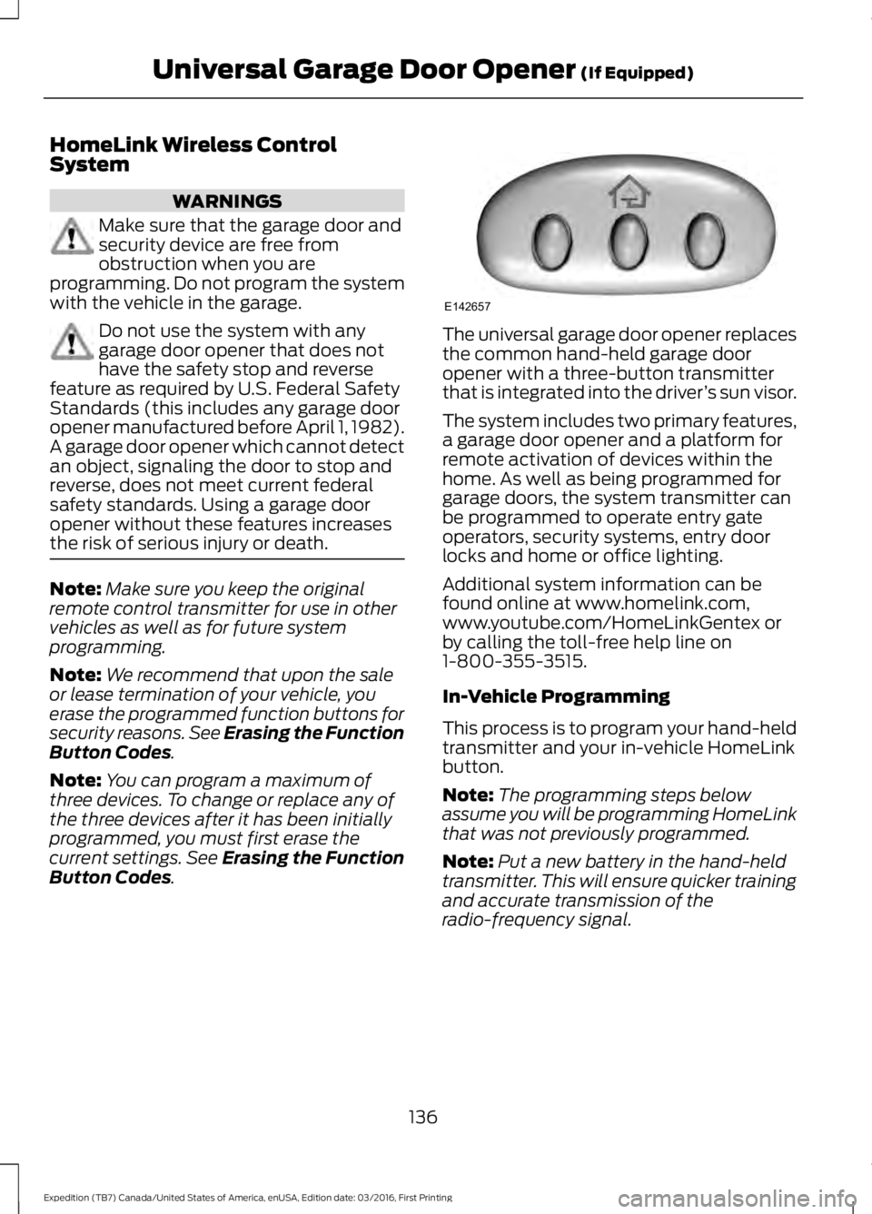
The universal garage door opener replacesthe common hand-held garage dooropener with a three-button transmitterthat is integrated into the driver’s sun visor.
The system includes two primary features,a garage door opener and a platform forremote activation of devices within thehome. As well as being programmed forgarage doors, the system transmitter canbe programmed to operate entry gateoperators, security systems, entry doorlocks and home or office lighting.
Additional system information can befound online at www.homelink.com,www.youtube.com/HomeLinkGentex orby calling the toll-free help line on1-800-355-3515.
In-Vehicle Programming
This process is to program your hand-heldtransmitter and your in-vehicle HomeLinkbutton.
Note:The programming steps belowassume you will be programming HomeLinkthat was not previously programmed.
Note:Put a new battery in the hand-heldtransmitter. This will ensure quicker trainingand accurate transmission of theradio-frequency signal.
136
Expedition (TB7) Canada/United States of America, enUSA, Edition date: 03/2016, First Printing
Universal Garage Door Opener (If Equipped)E142657
Page 162 of 500
AUTOMATIC TRANSMISSION
WARNINGS
Always set the parking brake fullyand make sure you shift the gearshiftlever to park (P). Switch the ignitionoff and remove the key whenever you leaveyour vehicle.
Do not use the tow/haul featurewhen driving in icy or slipperyconditions as the increased enginebraking can cause the rear wheels to slideand your vehicle to swing around with thepossible loss of vehicle control.
Understanding the Shift Positionsof your Automatic Transmission
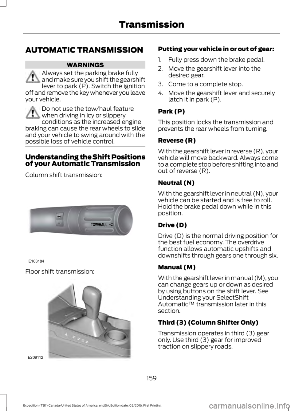
Column shift transmission:
Floor shift transmission:
Putting your vehicle in or out of gear:
1. Fully press down the brake pedal.
2. Move the gearshift lever into thedesired gear.
3. Come to a complete stop.
4. Move the gearshift lever and securelylatch it in park (P).
Park (P)
This position locks the transmission andprevents the rear wheels from turning.
Reverse (R)
With the gearshift lever in reverse (R), yourvehicle will move backward. Always cometo a complete stop before shifting into andout of reverse (R).
Neutral (N)
With the gearshift lever in neutral (N), yourvehicle can be started and is free to roll.Hold the brake pedal down while in thisposition.
Drive (D)
Drive (D) is the normal driving position forthe best fuel economy. The overdrivefunction allows automatic upshifts anddownshifts through gears one through six.
Manual (M)
With the gearshift lever in manual (M), youcan change gears up or down as desiredby using buttons on the shift lever. SeeUnderstanding your SelectShiftAutomatic™ transmission later in thissection.
Third (3) (Column Shifter Only)
Transmission operates in third (3) gearonly. Use third (3) gear for improvedtraction on slippery roads.
159
Expedition (TB7) Canada/United States of America, enUSA, Edition date: 03/2016, First Printing
TransmissionE163184 E209112
Page 164 of 500
Automatic Transmission AdaptiveLearning
This feature may increase durability andprovide consistent shift feel over the lifeof your vehicle. A new vehicle ortransmission may have firm shifts, softshifts or both. This operation is considerednormal and will not affect function ordurability of the transmission. Over time,the adaptive learning process will fullyupdate transmission operation.
SelectShift™ AutomaticTransmission (If Equipped)
This feature gives you the ability to changegears up or down as desired.
As long as the engine speed does notexceed the maximum allowable limit youcan downshift. SelectShift automaticallydownshifts at low engine speeds in orderto prevent engine stalls.
Note:Engine damage may occur if youmaintain excessive engine revving withoutshifting.
SelectShift does not automatically upshift,even if the engine is approaching the RPMlimit, unless the accelerator pedal is at fulltravel. Take notice of the shift indicatorlamp, which alerts you when to shift tomake sure you achieve the highest level ofefficiency and fuel economy.
Press the + toggle switch on the sideof the gearshift lever to activateSelectShift.
•Press the (+) button to upshift.
•Press the (-) button to downshift.
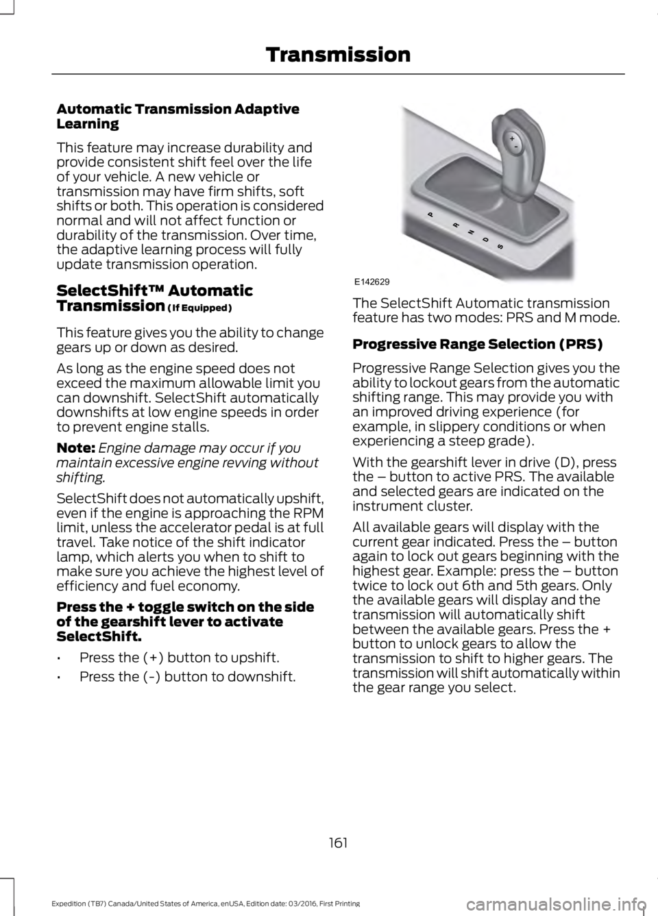
The SelectShift Automatic transmissionfeature has two modes: PRS and M mode.
Progressive Range Selection (PRS)
Progressive Range Selection gives you theability to lockout gears from the automaticshifting range. This may provide you withan improved driving experience (forexample, in slippery conditions or whenexperiencing a steep grade).
With the gearshift lever in drive (D), pressthe – button to active PRS. The availableand selected gears are indicated on theinstrument cluster.
All available gears will display with thecurrent gear indicated. Press the – buttonagain to lock out gears beginning with thehighest gear. Example: press the – buttontwice to lock out 6th and 5th gears. Onlythe available gears will display and thetransmission will automatically shiftbetween the available gears. Press the +button to unlock gears to allow thetransmission to shift to higher gears. Thetransmission will shift automatically withinthe gear range you select.
161
Expedition (TB7) Canada/United States of America, enUSA, Edition date: 03/2016, First Printing
TransmissionE142629
Page 166 of 500
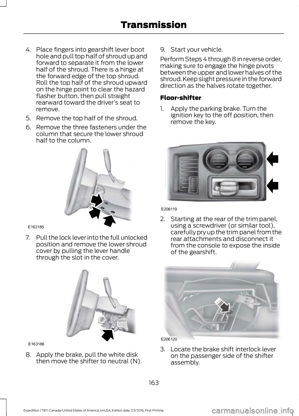
4. Place fingers into gearshift lever boothole and pull top half of shroud up andforward to separate it from the lowerhalf of the shroud. There is a hinge atthe forward edge of the top shroud.Roll the top half of the shroud upwardon the hinge point to clear the hazardflasher button, then pull straightrearward toward the driver’s seat toremove.
5. Remove the top half of the shroud.
6. Remove the three fasteners under thecolumn that secure the lower shroudhalf to the column.
7.Pull the lock lever into the full unlockedposition and remove the lower shroudcover by pulling the lever handlethrough the slot in the cover.
8. Apply the brake, pull the white diskthen move the shifter to neutral (N).
9. Start your vehicle.
Perform Steps 4 through 8 in reverse order,making sure to engage the hinge pivotsbetween the upper and lower halves of theshroud. Keep slight pressure in the forwarddirection as the halves rotate together.
Floor-shifter
1. Apply the parking brake. Turn theignition key to the off position, thenremove the key.
2. Starting at the rear of the trim panel,using a screwdriver (or similar tool),carefully pry up the trim panel from therear attachments and disconnect itfrom the console to expose the insideof the gearshift.
3. Locate the brake shift interlock leveron the passenger side of the shifterassembly.
163
Expedition (TB7) Canada/United States of America, enUSA, Edition date: 03/2016, First Printing
TransmissionE163185 E163186 E206119 E206120
Page 200 of 500
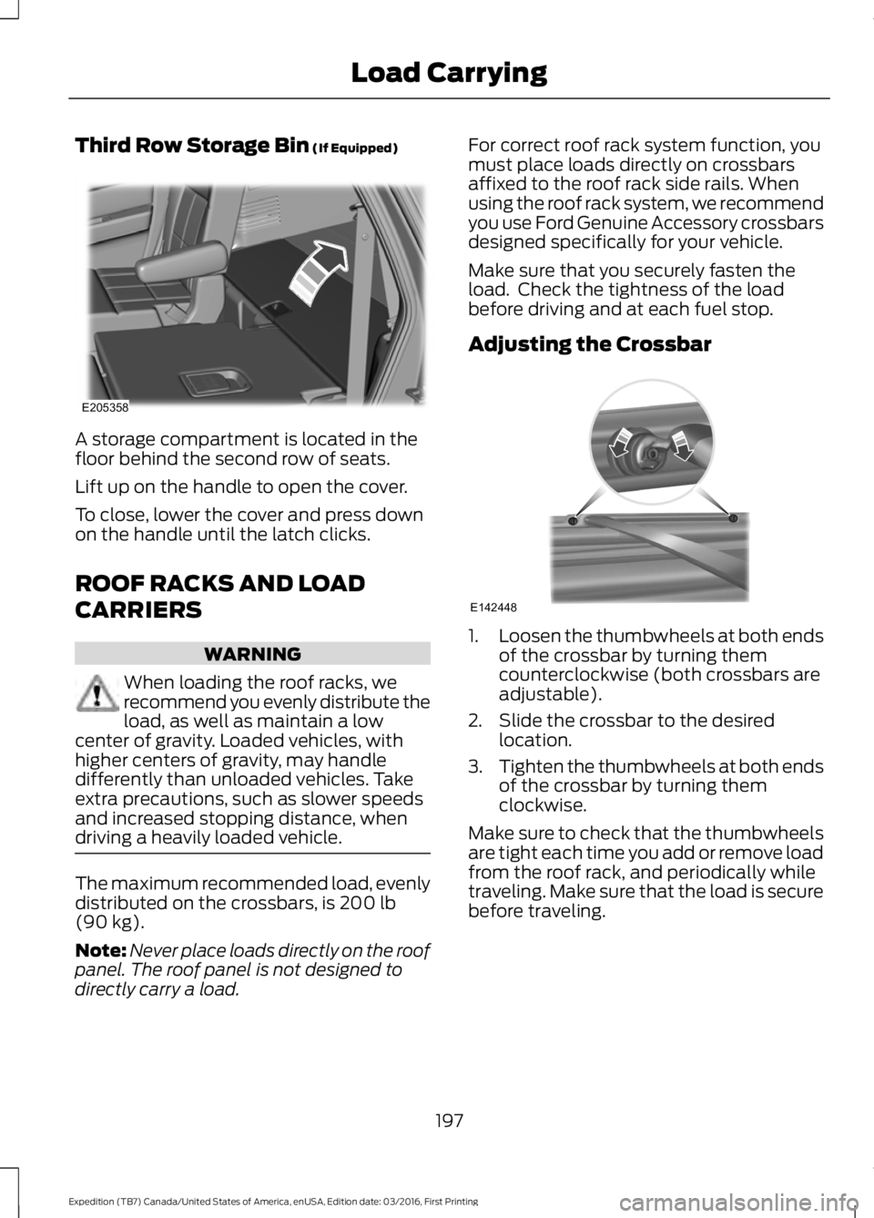
Third Row Storage Bin (If Equipped)
A storage compartment is located in thefloor behind the second row of seats.
Lift up on the handle to open the cover.
To close, lower the cover and press downon the handle until the latch clicks.
ROOF RACKS AND LOAD
CARRIERS
WARNING
When loading the roof racks, werecommend you evenly distribute theload, as well as maintain a lowcenter of gravity. Loaded vehicles, withhigher centers of gravity, may handledifferently than unloaded vehicles. Takeextra precautions, such as slower speedsand increased stopping distance, whendriving a heavily loaded vehicle.
The maximum recommended load, evenlydistributed on the crossbars, is 200 lb(90 kg).
Note:Never place loads directly on the roofpanel. The roof panel is not designed todirectly carry a load.
For correct roof rack system function, youmust place loads directly on crossbarsaffixed to the roof rack side rails. Whenusing the roof rack system, we recommendyou use Ford Genuine Accessory crossbarsdesigned specifically for your vehicle.
Make sure that you securely fasten theload. Check the tightness of the loadbefore driving and at each fuel stop.
Adjusting the Crossbar
1.Loosen the thumbwheels at both endsof the crossbar by turning themcounterclockwise (both crossbars areadjustable).
2. Slide the crossbar to the desiredlocation.
3.Tighten the thumbwheels at both endsof the crossbar by turning themclockwise.
Make sure to check that the thumbwheelsare tight each time you add or remove loadfrom the roof rack, and periodically whiletraveling. Make sure that the load is securebefore traveling.
197
Expedition (TB7) Canada/United States of America, enUSA, Edition date: 03/2016, First Printing
Load CarryingE205358 E142448
Page 211 of 500
Integrated Hitch Rating
WARNING
Towing trailers beyond the maximumtongue weight exceeds the limit ofthe towing system and could resultin vehicle structural damage, loss of vehiclecontrol and personal injury.
The standard integrated hitch has tworatings depending on mode of operation:
•Weight-carrying mode requires a drawbar and hitch ball. The draw barsupports all the vertical tongue load ofthe trailer.
•Weight-distributing mode requires anaftermarket weight-distributingsystem, which includes draw bar, hitchball, spring bars and snap-up brackets.This system distributes the verticaltongue load of the trailer between thetruck and the trailer.
Maximum Tongue WeightMaximum Trailer WeightMode
600 lb (272 kg)6000 lb (2721 kg)Weight carrying
920 lb (417 kg)9200 lb (4173 kg)Weight distributing
Note:These are hitch ratings only. Actualvehicle ratings are dependent on engine,transmission and axle combinations.
Weight-distributing Hitch - Vehicleswithout Automatic LevelingSuspension
WARNING
Do not adjust a weight-distributinghitch to any position where the rearbumper of the vehicle is higher thanit was before attaching the trailer. Doingso will defeat the function of theweight-distributing hitch, which may causeunpredictable handling, and could resultin serious personal injury.
When hooking-up a trailer using aweight-distributing hitch, always use thefollowing procedure:
1. Park the loaded vehicle, without thetrailer, on a level surface.
2. Measure the height to the top of yourvehicle's front wheel opening on thefender. This is H1.
3.Attach the loaded trailer to your vehiclewithout the weight-distributing barsconnected.
4. Measure the height to the top of yourvehicle's front wheel opening on thefender a second time. This is H2.
5. Install and adjust the tension in theweight-distributing bars so that theheight of your vehicle's front wheelopening on the fender is approximatelyhalf the way down from H2, toward H1.
6.Check that the trailer is level or slightlynose down toward your vehicle. If not,adjust the ball height accordingly andrepeat Steps 2-6.
When the trailer is level or slightly nosedown toward the vehicle:
•Lock the bar tension adjuster in place.
•Check that the trailer tongue securelyattaches and locks onto the hitch.
•Install safety chains, lighting, and trailerbrake controls as required by law or thetrailer manufacturer.
208
Expedition (TB7) Canada/United States of America, enUSA, Edition date: 03/2016, First Printing
Towing
Page 212 of 500
Weight-distributing Hitch - Vehicleswith Automatic Leveling Suspension
WARNING
Do not adjust a weight-distributinghitch to any position where the rearbumper of the vehicle is higher thanit was before attaching the trailer. Doingso will defeat the function of theweight-distributing hitch, which may causeunpredictable handling, and could resultin serious personal injury.
Note:If you do not move the loaded vehiclefor approximately 12 hours, the levelingsystem may bleed down to a lower height.This can be especially apparent if you leavea trailer attached to the parked vehicle forlong periods. You must drive your vehicle inorder to re-level the suspension.
When hooking-up a trailer using aweight-distributing hitch, always use thefollowing procedure:
1. Load the interior of the vehicle to aweight similar to that which you intendto carry when towing. This includesthings such as passenger weight andcargo.
2. Drive the vehicle for approximately 2miles (3 kilometers) to re-level thesuspension.
3. Park the loaded vehicle, without thetrailer, on a level surface.
4. Measure the height to the top of yourvehicle's front wheel opening on thefender. This is H1.
5.Attach the loaded trailer to your vehiclewithout the weight-distributing barsconnected.
6.Make sure you securely attach and lockthe trailer tongue to the hitch.
7.Install safety chains, lighting, and trailerbrake controls as required by law or thetrailer manufacturer.
8. Drive the vehicle and trailer at 20–25mph (32–40 km/h) for approximately2 miles (3 kilometers) to re-level thesuspension.
9. Park your vehicle and trailer on a levelsurface.
10.Measure the height to the top of yourvehicle's front wheel opening on thefender a second time. This is H2.
11. Install and adjust the tension in theweight-distributing bars so that theheight of your vehicle's front wheelopening on the fender isapproximately half the way downfrom H2, toward H1.
12. Check that the trailer is level orslightly nose down toward yourvehicle. If not, remove the trailer,adjust the ball height accordingly andrepeat Steps 5-11.
When the trailer is level or slightly nosedown toward the vehicle:
•Lock the bar tension adjuster in place.
•Check that the trailer tongue securelyattaches and locks onto the hitch.
•Install safety chains, lighting, and trailerbrake controls as required by law or thetrailer manufacturer.
Safety Chains
Note:Do not attach safety chains to thebumper.
Always connect the safety chains to theframe or hook retainers of your vehiclehitch.
To connect the safety chains, cross thechains under the trailer tongue and allowenough slack for turning tight corners. Donot allow the chains to drag on the ground.
209
Expedition (TB7) Canada/United States of America, enUSA, Edition date: 03/2016, First Printing
Towing
Page 213 of 500
Trailer Brakes
WARNING
Do not connect a trailer's hydraulicbrake system directly to yourvehicle's brake system. Your vehiclemay not have enough braking power andyour chances of having a collision greatlyincrease.
Electric brakes and manual, automatic orsurge-type trailer brakes are safe if youinstall them properly and adjust them tothe manufacturer's specifications. Thetrailer brakes must meet local and federalregulations.
The rating for the tow vehicle's brakingsystem operation is at the gross vehicleweight rating, not the gross combinedweight rating.
Separate functioning brake systemsare required for safe control of towedvehicles and trailers weighing morethan 1500 pounds (680 kilograms)when loaded.
Integrated Trailer Brake Controller (IfEquipped)
WARNING
The Ford trailer brake controller hasbeen verified to be compatible withtrailers having electric-actuateddrum brakes (one to four axles) and mostelectric-over-hydraulic brakes. It will notactivate hydraulic surge-style trailerbrakes. It is the responsibility of thecustomer to ensure that the trailer brakesare adjusted appropriately, functioningnormally and all electric connections areproperly made. Failure to do so may resultin loss of vehicle control, crash or seriousinjury.
When used properly, the trailer brakecontroller assists in smooth and effectivetrailer braking by powering the trailer’selectric or electric-over-hydraulic brakeswith a proportional output based on thetowing vehicle’s brake pressure.
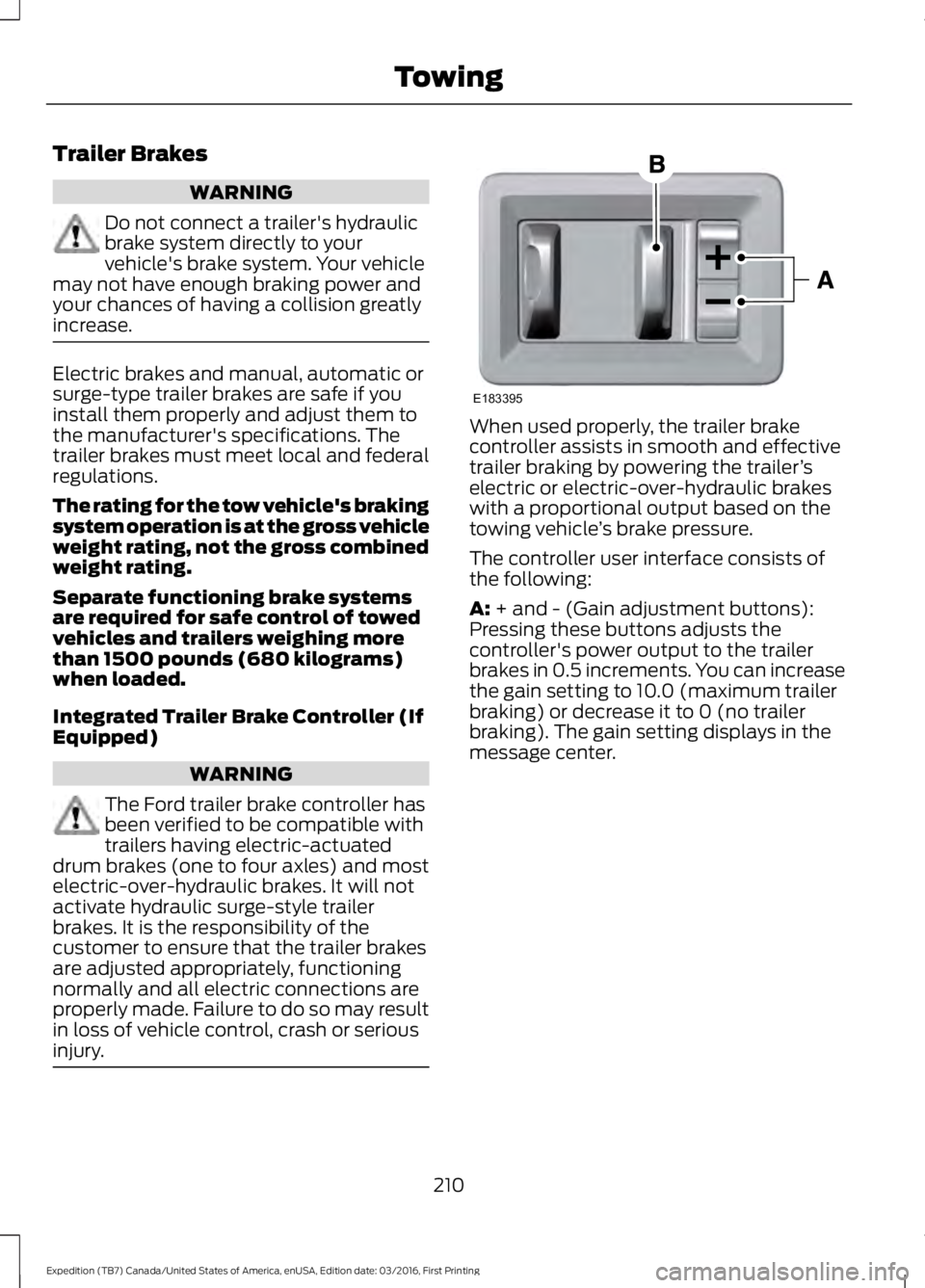
The controller user interface consists ofthe following:
A: + and - (Gain adjustment buttons):Pressing these buttons adjusts thecontroller's power output to the trailerbrakes in 0.5 increments. You can increasethe gain setting to 10.0 (maximum trailerbraking) or decrease it to 0 (no trailerbraking). The gain setting displays in themessage center.
210
Expedition (TB7) Canada/United States of America, enUSA, Edition date: 03/2016, First Printing
TowingE183395