2017 FORD EXPEDITION EL clock
[x] Cancel search: clockPage 257 of 500
If you see any corrosion on the battery orterminals, remove the cables from theterminals and clean with a wire brush. Youcan neutralize the acid with a solution ofbaking soda and water.
Because your vehicle’s engine iselectronically controlled by a computer,some control conditions are maintainedby power from the battery. When thebattery is disconnected or a new batteryis installed, the engine must relearn its idleand fuel trim strategy for optimumdriveability and performance. Flexible fuelvehicles (FFV) must also relearn theethanol content of the fuel for optimumdriveability and performance.
To restore the settings, do the following:
1. Apply the parking brake.
2. Shift into park (P) or neutral (N).
3. Switch off all accessories.
4. Press the brake pedal and start yourvehicle.
5. Run the engine until it reaches normaloperating temperature. While theengine is warming up, complete thefollowing: Reset the clock. See AudioSystem (page 313). Reset the powerwindows bounce-back feature. SeeWindows and Mirrors (page 79).Reset the radio station presets. SeeAudio System (page 313).
6.Allow the engine to idle for at least oneminute.
7.Drive the vehicle at least 10 mi (16 km)to completely relearn the idle trim andfuel trim strategy.
Note:If you do not allow the engine torelearn the idle and fuel trim strategy, theidle quality of your vehicle may be adverselyaffected until the engine computereventually relearns the idle trim and fueltrim strategy.
Note:For flexible fuel vehicles, if you areoperating on E85, you may experience poorstarts or an inability to start the engine anddriveability problems until the fuel trim andethanol content have been relearned.
Make sure that you dispose of old batteriesin an environmentally friendly way. Seekadvice from your local authority aboutrecycling old batteries.
If storing your vehicle for more than 30days without recharging the battery, werecommend that you disconnect thebattery cables to maintain battery chargefor quick starting.
Battery Management System (If
Equipped)
The battery management system monitorsbattery conditions and takes actions toextend battery life. If excessive batterydrain is detected, the system temporarilydisables some electrical systems toprotect the battery.
Systems included are:
•Heated rear window.
•Heated seats.
•Climate control.
•Heated steering wheel.
•Audio unit.
•Navigation system.
A message may appear in the informationdisplays to alert you that batteryprotection actions are active. Thesemessages are only for notification that anaction is taking place, and not intended toindicate an electrical problem or that thebattery requires replacement.
254
Expedition (TB7) Canada/United States of America, enUSA, Edition date: 03/2016, First Printing
Maintenance
Page 260 of 500
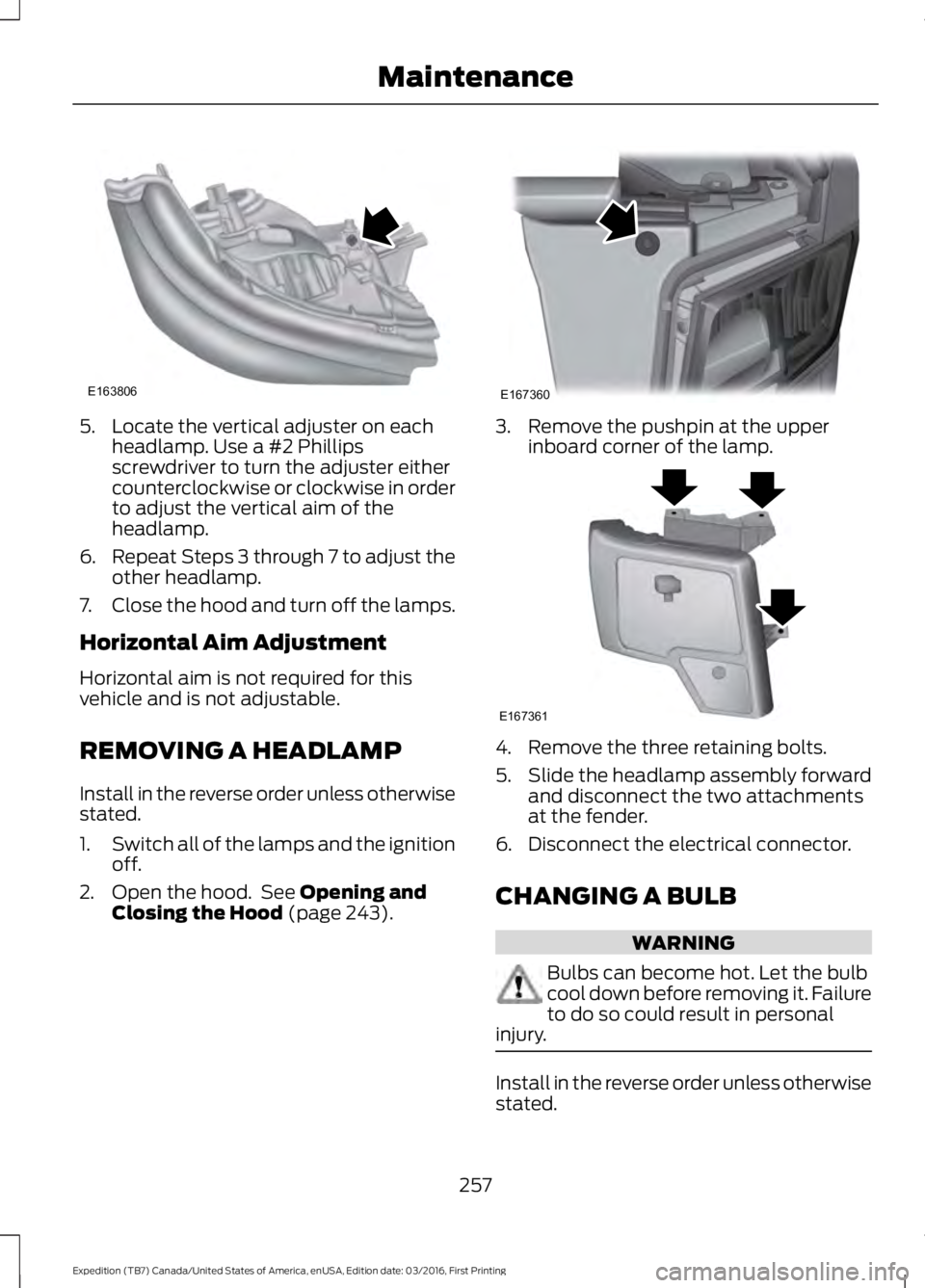
5. Locate the vertical adjuster on eachheadlamp. Use a #2 Phillipsscrewdriver to turn the adjuster eithercounterclockwise or clockwise in orderto adjust the vertical aim of theheadlamp.
6.Repeat Steps 3 through 7 to adjust theother headlamp.
7.Close the hood and turn off the lamps.
Horizontal Aim Adjustment
Horizontal aim is not required for thisvehicle and is not adjustable.
REMOVING A HEADLAMP
Install in the reverse order unless otherwisestated.
1.Switch all of the lamps and the ignitionoff.
2. Open the hood. See Opening andClosing the Hood (page 243).
3. Remove the pushpin at the upperinboard corner of the lamp.
4. Remove the three retaining bolts.
5.Slide the headlamp assembly forwardand disconnect the two attachmentsat the fender.
6. Disconnect the electrical connector.
CHANGING A BULB
WARNING
Bulbs can become hot. Let the bulbcool down before removing it. Failureto do so could result in personalinjury.
Install in the reverse order unless otherwisestated.
257
Expedition (TB7) Canada/United States of America, enUSA, Edition date: 03/2016, First Printing
MaintenanceE163806 E167360 E167361
Page 261 of 500
Note:If the bulb is accidentally touched,clean it with rubbing alcohol beforeinstalling it.
Headlamp Bulb
1.Switch all of the lamps and the ignitionoff.
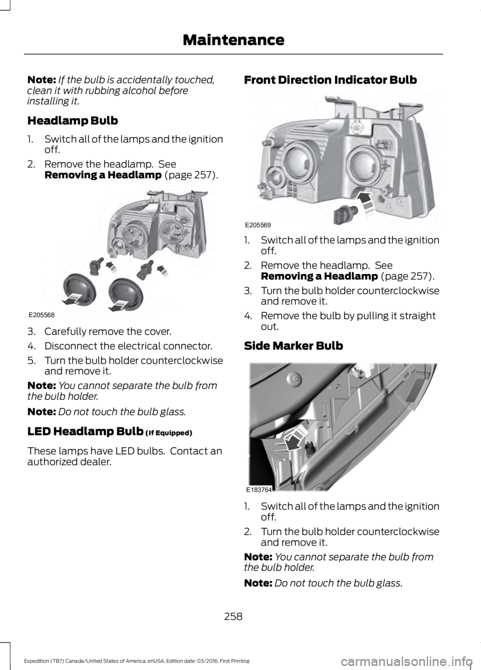
2. Remove the headlamp. SeeRemoving a Headlamp (page 257).
3. Carefully remove the cover.
4. Disconnect the electrical connector.
5.Turn the bulb holder counterclockwiseand remove it.
Note:You cannot separate the bulb fromthe bulb holder.
Note:Do not touch the bulb glass.
LED Headlamp Bulb (If Equipped)
These lamps have LED bulbs. Contact anauthorized dealer.
Front Direction Indicator Bulb
1.Switch all of the lamps and the ignitionoff.
2. Remove the headlamp. SeeRemoving a Headlamp (page 257).
3.Turn the bulb holder counterclockwiseand remove it.
4. Remove the bulb by pulling it straightout.
Side Marker Bulb
1.Switch all of the lamps and the ignitionoff.
2.Turn the bulb holder counterclockwiseand remove it.
Note:You cannot separate the bulb fromthe bulb holder.
Note:Do not touch the bulb glass.
258
Expedition (TB7) Canada/United States of America, enUSA, Edition date: 03/2016, First Printing
MaintenanceE205568 E205569 E183764
Page 262 of 500
LED Direction Indicator and SideMarker Bulbs (If Equipped)
These lamps have LED bulbs. Contact anauthorized dealer.
Fog Lamp Bulb (If Equipped)
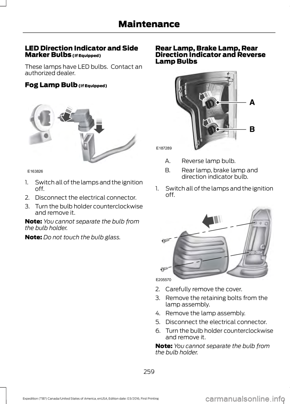
1.Switch all of the lamps and the ignitionoff.
2. Disconnect the electrical connector.
3.Turn the bulb holder counterclockwiseand remove it.
Note:You cannot separate the bulb fromthe bulb holder.
Note:Do not touch the bulb glass.
Rear Lamp, Brake Lamp, RearDirection Indicator and ReverseLamp Bulbs
Reverse lamp bulb.A.
Rear lamp, brake lamp anddirection indicator bulb.B.
1.Switch all of the lamps and the ignitionoff.
2. Carefully remove the cover.
3. Remove the retaining bolts from thelamp assembly.
4. Remove the lamp assembly.
5. Disconnect the electrical connector.
6.Turn the bulb holder counterclockwiseand remove it.
Note:You cannot separate the bulb fromthe bulb holder.
259
Expedition (TB7) Canada/United States of America, enUSA, Edition date: 03/2016, First Printing
MaintenanceE163826 E187289 E205570
Page 263 of 500

LED Rear Lamp, Brake Lamp, RearDirection Indicator and ReverseLamp Bulbs (If Equipped)
These lamps have LED bulbs. Contact anauthorized dealer.
Central High-mounted Brake LampBulb
1.Switch all of the lamps and the ignitionoff.
2. Remove the retaining bolts from thelamp assembly.
3. Remove the lamp and unclip the bulbholder.
4. Remove the bulb by pulling it straightout.
LED Central High-mounted BrakeLamp Bulb (If Equipped)
These lamps have LED bulbs. Contact anauthorized dealer.
License Plate Lamp Bulb
1. Use a suitable tool, for example ascrewdriver, to carefully remove thelamp.
2.Turn the bulb holder counterclockwiseand remove it.
3. Remove the bulb by pulling it straightout.
Side Direction Indicator Bulb
These lamps have LED bulbs. Contact anauthorized dealer.
BULB SPECIFICATION CHART
Replacement bulbs are specified in thechart below. Headlamp bulbs must bemarked with an authorized D.O.T. markingfor North America to make sure they havethe proper lamp performance, lightbrightness, light pattern and safe visibility.The correct bulbs will not damage thelamp assembly or void the lamp assemblywarranty and will provide quality bulbillumination time.
260
Expedition (TB7) Canada/United States of America, enUSA, Edition date: 03/2016, First Printing
MaintenanceE205572 E205573 E205571
Page 299 of 500

•To reduce the chances of interferencefrom another vehicle, perform thesystem reset procedure at least threefeet (one meter) away from anotherFord Motor Company vehicleundergoing the system reset procedureat the same time.
•Do not wait more than two minutesbetween resetting each tire sensor orthe system will time-out and the entireprocedure will have to be repeated onall four wheels.
•A double horn will sound indicating theneed to repeat the procedure.
Performing the System Reset Procedure
Read the entire procedure beforeattempting.
1. Drive the vehicle above 20 mph (32km/h) for at least two minutes, thenpark in a safe location where you caneasily get to all four tires and haveaccess to an air pump.
2.Place the ignition in the off position andkeep the key in the ignition.
3. Cycle the ignition to the on positionwith the engine off.
4. Turn the hazard flashers on then offthree times. You must accomplish thiswithin 10 seconds. If the reset modehas been entered successfully, the hornwill sound once, the system indicatorwill flash and a message is shown inthe information display. If this does notoccur, please try again starting at Step2. If after repeated attempts to enterthe reset mode, the horn does notsound, the system indicator does notflash and no message is shown in theinformation display, seek service fromyour authorized dealer.
5. Train the tire pressure monitoringsystem sensors in the tires using thefollowing system reset sequencestarting with the left front tire in thefollowing clockwise order: Left front(driver's side front tire), Right front(passenger's side front tire), Right rear(passenger's side rear tire), Left rear(driver's side rear tire).
6. Remove the valve cap from the valvestem on the left front tire. Decrease theair pressure until the horn sounds.
Note:The single horn chirp confirms thatthe sensor identification code has beenlearned by the module for this position. If adouble horn is heard, the reset procedurewas unsuccessful, and you must repeat it.
7. Remove the valve cap from the valvestem on the right front tire. Decreasethe air pressure until the horn sounds.
8. Remove the valve cap from the valvestem on the right rear tire. Decrease theair pressure until the horn sounds.
9. Remove the valve cap from the valvestem on the left rear tire. Decrease theair pressure until the horn sounds.Training is complete after the hornsounds for the last tire trained (driver'sside rear tire), the system indicatorstops flashing, and a message is shownin the information display.
10.Turn the ignition off. If two short hornbeeps are heard, the reset procedurewas unsuccessful and you mustrepeat it. If after repeating theprocedure and two short beeps areheard when the ignition is turned tooff, seek assistance from yourauthorized dealer.
296
Expedition (TB7) Canada/United States of America, enUSA, Edition date: 03/2016, First Printing
Wheels and Tires
Page 303 of 500
Park on a level surface, activate the hazardflashers and set the parking brake. Then,place the transmission in park (P) and turnthe engine off.
Removing the Jack and Tools
Note:Pay close attention to the orientationof the bag, because it will have to bereinstalled after changing the tire.
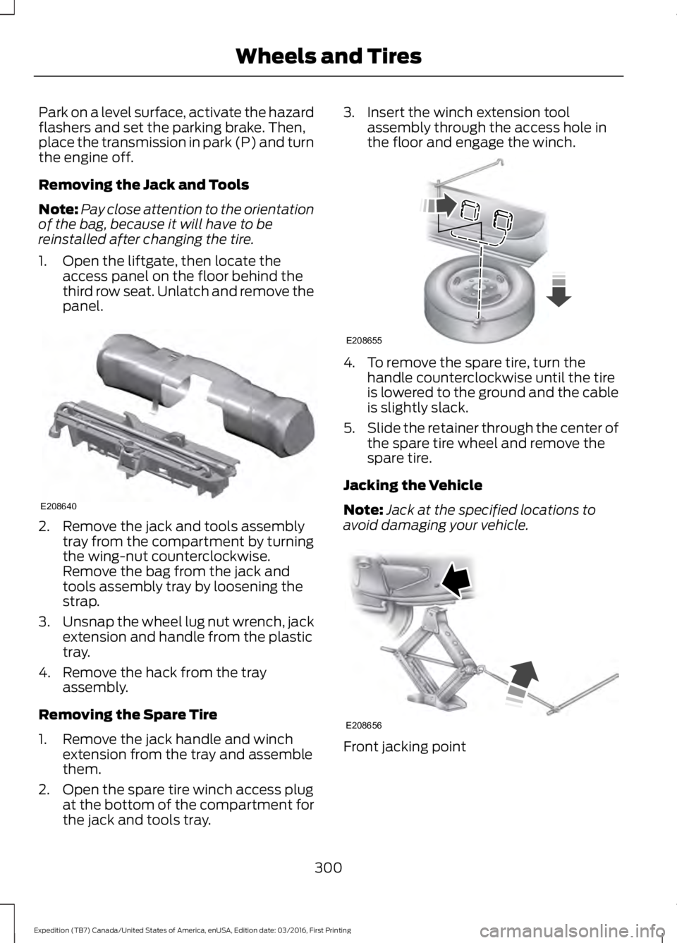
1. Open the liftgate, then locate theaccess panel on the floor behind thethird row seat. Unlatch and remove thepanel.
2. Remove the jack and tools assemblytray from the compartment by turningthe wing-nut counterclockwise.Remove the bag from the jack andtools assembly tray by loosening thestrap.
3.Unsnap the wheel lug nut wrench, jackextension and handle from the plastictray.
4. Remove the hack from the trayassembly.
Removing the Spare Tire
1. Remove the jack handle and winchextension from the tray and assemblethem.
2. Open the spare tire winch access plugat the bottom of the compartment forthe jack and tools tray.
3. Insert the winch extension toolassembly through the access hole inthe floor and engage the winch.
4. To remove the spare tire, turn thehandle counterclockwise until the tireis lowered to the ground and the cableis slightly slack.
5.Slide the retainer through the center ofthe spare tire wheel and remove thespare tire.
Jacking the Vehicle
Note:Jack at the specified locations toavoid damaging your vehicle.
Front jacking point
300
Expedition (TB7) Canada/United States of America, enUSA, Edition date: 03/2016, First Printing
Wheels and TiresE208640 E208655 E208656
Page 304 of 500
Rear jacking point
1.With the vehicle on level ground, blockboth sides of the wheel diagonallyopposite (other side and end of thevehicle) to the wheel being changed.Do not jack the vehicle on a hill orincline.
2. Obtain the spare tire and jack toolsfrom their storage locations.
3. Use the tip of the jack handle toremove any wheel trim.
4. Loosen each wheel lug nut one-halfturn counterclockwise but do notremove them until the wheel is raisedoff the ground.
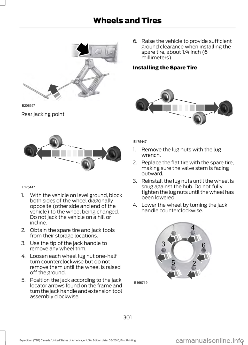
5. Position the jack according to the jacklocator arrows found on the frame andturn the jack handle and extension toolassembly clockwise.
6. Raise the vehicle to provide sufficientground clearance when installing thespare tire, about 1/4 inch (6millimeters).
Installing the Spare Tire
1. Remove the lug nuts with the lugwrench.
2.Replace the flat tire with the spare tire,making sure the valve stem is facingoutward.
3.Reinstall the lug nuts until the wheel issnug against the hub. Do not fullytighten the lug nuts until the wheel hasbeen lowered.
4. Lower the wheel by turning the jackhandle counterclockwise.
301
Expedition (TB7) Canada/United States of America, enUSA, Edition date: 03/2016, First Printing
Wheels and TiresE208657 E175447 E175447 E166719
1
3
5 4
6
2