2017 FIAT TIPO 5DOORS STATION WAGON change wheel
[x] Cancel search: change wheelPage 26 of 264
The higher the sensitivity, the lower the
amount of external light needed to
automatically switch the external lights
on.
Function activation
Turn the left stalk ring nut to position
.
IMPORTANT The function can only be
activated with the ignition device at
MAR.
Function deactivation
To deactivate the function, turn the left
stalk ring nut to a position other than
.
MAIN BEAM HEADLIGHTS
With ring nut in position, push the
stalk forward toward the dashboard
(stable position). The
warning light
switches on in the instrument panel.
They are switched off by pulling the
stalk towards the steering wheel.
MAIN BEAM HEADLIGHTS
Flashing the headlights
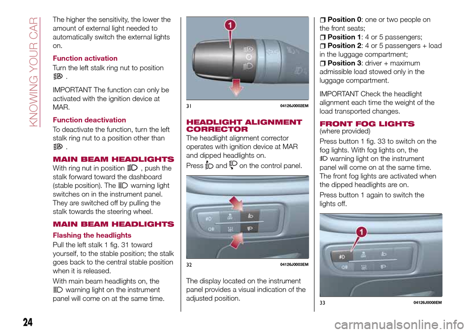
Pull the left stalk 1 fig. 31 toward
yourself, to the stable position; the stalk
goes back to the central stable position
when it is released.
With main beam headlights on, the
warning light on the instrument
panel will come on at the same time.
HEADLIGHT ALIGNMENT
CORRECTOR
The headlight alignment corrector
operates with ignition device at MAR
and dipped headlights on.
Press
andon the control panel.
The display located on the instrument
panel provides a visual indication of the
adjusted position.
Position 0: one or two people on
the front seats;
Position 1: 4 or 5 passengers;
Position 2: 4 or 5 passengers + load
in the luggage compartment;
Position 3: driver + maximum
admissible load stowed only in the
luggage compartment.
IMPORTANT Check the headlight
alignment each time the weight of the
load transported changes.
FRONT FOG LIGHTS
(where provided)
Press button 1 fig. 33 to switch on the
fog lights. With fog lights on, the
warning light on the instrument
panel will come on at the same time.
The front fog lights are activated when
the dipped headlights are on.
Press button 1 again to switch the
lights off.
3104126J0002EM
3204126J0003EM
3304126J0008EM
24
KNOWING YOUR CAR
Page 37 of 264
When the CITY function is on, the
steering wheel effort is lighter, making
parking easier: therefore, this function is
particularly useful for driving in city
centres.
To ensure steering uniformity, when the
key is pressed while the steering wheel
is being turned, the change of force will
only be felt when it is turned in the
opposite direction, or the steering
wheel is released.
WARNING
27)It is absolutely forbidden to carry out
any after-market operation involving
steering system or steering column
modifications (e.g. installation of anti-theft
device) that could adversely affect
performance, invalidate the warranty, cause
serious safety problems and also result in
the car not meeting type-approval
requirements.
28)Before performing any maintenance
operations, always stop the engine and
remove the key from the ignition to lock the
steering column (especially when the car
wheels are not touching the ground). If this
is not possible (for example if the key
needs to be turned to MAR or the engine
must be running), remove the main fuse
that protects the electric power steering.
LUGGAGE
COMPARTMENT
IMPORTANT When travelling, do not
put any object on the rear parcel shelf
because they can injure passengers in
the event of an accident or sudden
braking.
OPENING
29)
Tailgate opening
When the central locking system is
unlocked, the tailgate can be opened
from outside the car using the electric
opening handle (where provided)
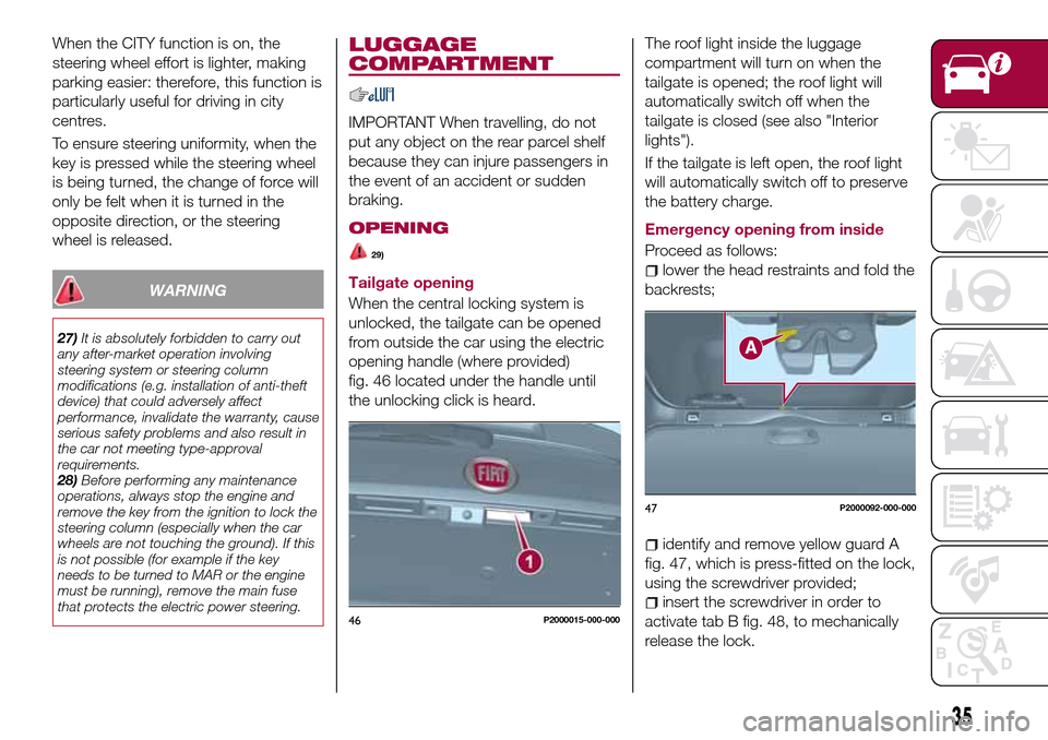
fig. 46 located under the handle until
the unlocking click is heard.The roof light inside the luggage
compartment will turn on when the
tailgate is opened; the roof light will
automatically switch off when the
tailgate is closed (see also "Interior
lights").
If the tailgate is left open, the roof light
will automatically switch off to preserve
the battery charge.
Emergency opening from inside
Proceed as follows:lower the head restraints and fold the
backrests;
identify and remove yellow guard A
fig. 47, which is press-fitted on the lock,
using the screwdriver provided;
insert the screwdriver in order to
activate tab B fig. 48, to mechanically
release the lock.46P2000015-000-000
47P2000092-000-000
35
Page 44 of 264
LPG MULTIPOINT
INJECTION SYSTEM
This product is produced by working
closely with qualified suppliers in the
LPG sector.
The injection system used on the car is
an efficient system in terms of engine
performance and is based on the
injection of LPG in a gaseous state.
In this system with four injectors, one
for each intake manifold, the fuel is
injected directly into the engine heat
transfer ducts, thereby metering the
LPG very precisely improving
combustion and, at the same time,
excluding any possibility of flame return.
By adapting the electronic control
technology of petrol engines to meet
LPG specifications, significant results in
terms of driveability and controlling
exhaust emissions have been obtained.
When running on LPG the engine has
almost the same torque and power
features as when running on petrol:
consequently, the car performance can
be compared.
SELECTION OF THE FUEL
SUPPLY TYPE
The car is configured for running
independently on either petrol or LPG.
The engine always starts up on petrol,
with automatic switching to LPG whenthe best conditions are achieved
(engine water temperature, minimum
engine rpm limit) for switching to LPG.
In addition, it is advisable to periodically
use up the petrol in the tank (until the
reserve warning light comes on) in order
to ensure that the petrol does not
become old and possibly deteriorate.
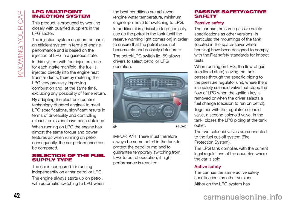
The petrol/LPG switch fig. 69 allows
drivers to select petrol or LPG
operation.
IMPORTANT There must therefore
always be some petrol in the tank to
protect the petrol pump and to
guarantee temporary switching from
LPG to petrol operation, if high
performance is required.PASSIVE SAFETY/ACTIVE
SAFETY
Passive safety
The car has the same passive safety
specifications as other versions. In
particular, the mountings of the tank
(located in the space-saver wheel
housing) have been designed to comply
with the Fiat safety standards for impact
tests.
When running on LPG, the flow of gas
(in a liquid state) leaving the tank
passes through the specific piping to
the pressure regulator unit, where there
is a safety solenoid valve that stops the
flow of LPG when the ignition key is
removed or when the driver selects a
fuel change (decision to run on petrol).
Together with the regulator solenoid
valve, a second solenoid valve, in the
tank, closes the LPG piping at the tank
outlet.
The two solenoid valves are connected
to the fuel cut-off system (Fire
Protection System).
The LPG tank complies with the current
legal regulations of the countries where
the car is sold.
Active safety
The car has the same active safety
specifications as other versions.
Although the LPG system has
69PGL00001
42
KNOWING YOUR CAR
Page 56 of 264
DISPLAY
DESCRIPTION
The vehicle is equipped with a display
that can show useful information to the
driver while driving.
With the ignition device in STOP
position and ignition key removed, the
display lights up and shows the time
and total odometer reading (in km or
miles) for a few seconds when a door is
opened/closed.
GEAR SHIFT INDICATOR
The Gear Shift Indicator (GSI) system
advises the driver to change gear
through a special indication on the
display.
Through the GSI, the driver is informed
that the gear change will allow a
reduction in fuel consumption.
When the
symbol appears on the
display, the GSI suggests switching to a
higher gear, while when the
symbol
is displayed, the GSI suggests
changing to a lower gear.
The indication in the display remains
until a gear is shifted or the driving
conditions go back to a situation where
gearshifting is not required to improve
consumption.
RECONFIGURABLE
MULTIFUNCTION
DISPLAY
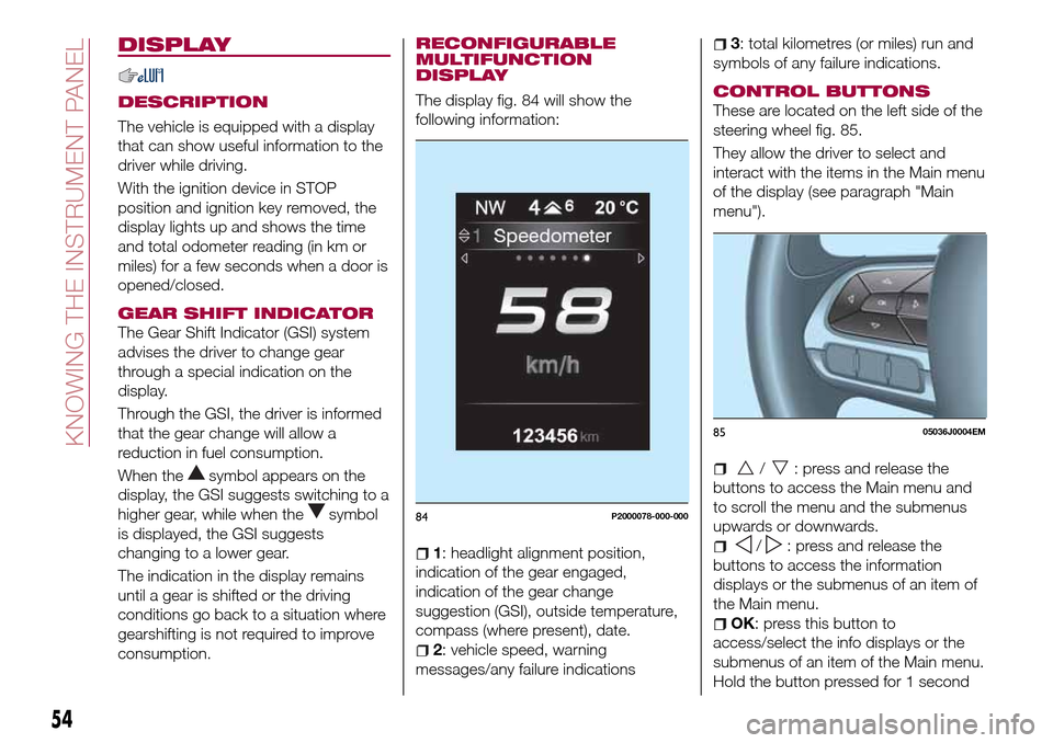
The display fig. 84 will show the
following information:
1: headlight alignment position,
indication of the gear engaged,
indication of the gear change
suggestion (GSI), outside temperature,
compass (where present), date.
2: vehicle speed, warning
messages/any failure indications
3: total kilometres (or miles) run and
symbols of any failure indications.
CONTROL BUTTONS
These are located on the left side of the
steering wheel fig. 85.
They allow the driver to select and
interact with the items in the Main menu
of the display (see paragraph "Main
menu").
/: press and release the
buttons to access the Main menu and
to scroll the menu and the submenus
upwards or downwards.
/: press and release the
buttons to access the information
displays or the submenus of an item of
the Main menu.
OK: press this button to
access/select the info displays or the
submenus of an item of the Main menu.
Hold the button pressed for 1 second
84P2000078-000-000
8505036J0004EM
54
KNOWING THE INSTRUMENT PANEL
Page 58 of 264
display will be in km or miles according
to the unit of measurement set.
When the following scheduled servicing
is approaching ("coupon"), the word
"Service" will be displayed, followed by
the number of kilometres/miles or days
left, when the ignition device is turned
to MAR. Go to a Fiat Dealership, where
the "Scheduled Servicing Plan"
operations will be performed and the
message will be reset.
Driver Assist
This menu item allows you to view and
change the Adaptive Cruise Control
(ACC) settings on the instrument panel
display.
Audio
(function available in versions and
markets where present)
This Menu item allows some
information displayed on the
Uconnect™system to be repeated on
the instrument panel display (for further
information see the dedicated chapter).
Phone
(function available in versions and
markets where present)
This Menu item allows some
information displayed on the
Uconnect™system to be repeated on
the instrument panel display (for further
information see the dedicated chapter).The information displayed includes the
mobile pairing condition (mobile paired
or not paired), active/incoming/on hold
calls and the management of double
calls (first incoming, second on hold,
etc.).
In the phone menu, you can also select
3 sub-menus “SMS reader”, “recent
calls” and “favourite numbers” (available
with theUconnect™7'' HDsystem),
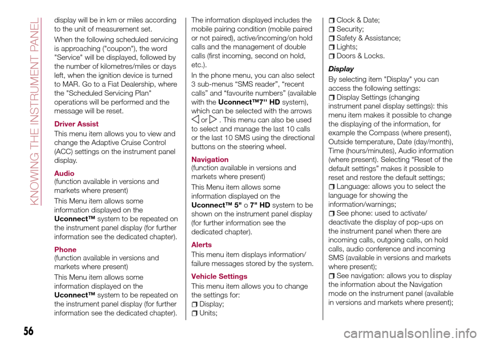
which can be selected with the arrows
or. This menu can also be used
to select and manage the last 10 calls
or the last 10 SMS using the directional
buttons on the steering wheel.
Navigation
(function available in versions and
markets where present)
This Menu item allows some
information displayed on the
Uconnect™ 5"o7" HDsystem to be
shown on the instrument panel display
(for further information see the
dedicated chapter).
Alerts
This menu item displays information/
failure messages stored by the system.
Vehicle Settings
This menu item allows you to change
the settings for:
Display;
Units;
Clock & Date;
Security;
Safety & Assistance;
Lights;
Doors & Locks.
Display
By selecting item "Display" you can
access the following settings:
Display Settings (changing
instrument panel display settings): this
menu item makes it possible to change
the displaying of the information, for
example the Compass (where present),
Outside temperature, Date (day/month),
Time (hours/minutes), Audio information
(where present). Selecting “Reset of the
default settings” makes it possible to
reset and restore the default settings;
Language: allows you to select the
language for showing the
information/warnings;
See phone: used to activate/
deactivate the display of pop-ups on
the instrument panel when there are
incoming calls, outgoing calls, on hold
calls, audio conference and incoming
SMS (available in versions and markets
where present);
See navigation: allows you to display
the information about the Navigation
mode on the instrument panel (available
in versions and markets where present);
56
KNOWING THE INSTRUMENT PANEL
Page 60 of 264
Doors & Locks
Select item "Doors & Locks" to make
the following adjustments:
Autoclose: activation/deactivation of
automatic door locking when the
vehicle is moving;
Flash Lights w/Lock: activation of the
direction indicator flashing at door
locking;
Auto Unlock on Exit: automatic
unlocking of the doors when exiting the
vehicle.
TRIP COMPUTER
The "Trip computer" is used to display
information on vehicle operation when
the ignition device is at MAR.
This function has two separate
memories, called “Trip A” and “Trip B”,
where the trip data are recorded
separately from each other.
Both memories can be reset.
“Trip A” and “Trip B” are used to display
the values relating to:
Autonomy
Instant consumption
Distance (distance travelled)
Average fuel consumption
Average speed
Trip time (driving time)
NOTE The displayed data can change
based on the vehicle version.
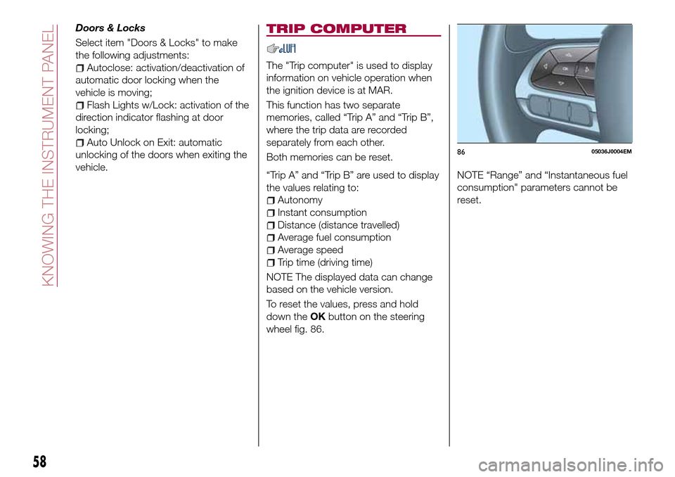
To reset the values, press and hold
down theOKbutton on the steering
wheel fig. 86.NOTE “Range” and “Instantaneous fuel
consumption" parameters cannot be
reset.
8605036J0004EM
58
KNOWING THE INSTRUMENT PANEL
Page 83 of 264

at least 20 minutes) which starts when
the RESET procedure is carried out.
The RESET procedure must be carried
out:
each time tyre pressure is modified;
when even only one tyre is changed;
when tyres are rotated/inverted;
when the space-saver wheel is fitted.
Before carrying out the RESET
procedure, inflate the tyres to the rated
pressure values specified in the inflation
pressure table (see "Wheels" paragraph
in the "Technical specifications"
chapter).
If the RESET is not carried out, in all
above cases, the
warning light may
give false indications on one or more
tyres.
To carry out the RESET, with the vehicle
stationary and the engine on, hold
down the Reset button
located on
the left control panel fig. 92 for at least
2 seconds.
When the RESET procedure has been
carried out, and depending on the type
of instrument panel, either only a buzzer
will be heard or the message "Reset
saved" will appear together with the
buzzer to indicate that self-learning has
started.Operating conditions
The system is active for speeds above
15 km/h.
In a few situations such as sporty
driving, particular conditions of the road
surface (e.g. icy, snowy, unsurfaced
roads) the signalling may be delayed or
partial in detecting the contemporary
deflation of more than one tyre.
Under special conditions (e.g. vehicle
loaded asymmetrically on one side,
towing a trailer, damaged or worn tyre,
fitting the space-saver wheel, use of the
"Fix&Go Automatic" tyre repair kit, fitting
snow chains, fitting different tyres on
the axles) the system may provide false
indications or be temporarily
deactivated.
If the system is temporarily deactivated
the
warning light flashes for about
75 seconds and then is continuouslyon; at the same time, the display shows
a warning message.
This indication is displayed also after
the engine has been switched off and
then on again if the correct operating
conditions are not restored.
In the case of abnormal signals, it is
recommended to perform the RESET
procedure. If the signals reappear once
the RESET procedure has started,
check that the type of tyres used are
the same on all four wheels and that the
tyres are not damaged; if the
space-saver wheel is being used, refit
the wheel with a tire with normal
dimensions instead of the space-saver
wheel as soon as possible; if possible
remove the snow chains; make sure
that the load is distributed correctly and
repeat the RESET procedure, driving on
a clean and surfaced road. If the signals
persist, contact a Fiat Dealership.
WARNING
61)The system is an aid for the driver, who
must always pay full attention while driving.
The responsibility always rests with the
driver, who must take into account the
traffic conditions in order to drive in
complete safety. The driver must always
maintain a safe distance from the vehicle in
front.
9206056J0001EM
81
Page 119 of 264
“Adaptive Cruise Control” mode
to hold an appropriate distance
between vehicles (a dedicated message
is shown on the instrument panel
display);
electronic “Cruise Control” mode
to hold the vehicle at a constant
preset speed.
To change the operation mode, use the
button on the steering wheel (see that
described on the following pages).
The "electronic Cruise Control" does
not vary the speed according to the
presence or not of vehicles ahead.
Always adjust the speed according to
traffic conditions.
ADAPTIVE CRUISE
CONTROL ACTIVATION/
DEACTIVATION
Activation
To activate the device, press and
release the button
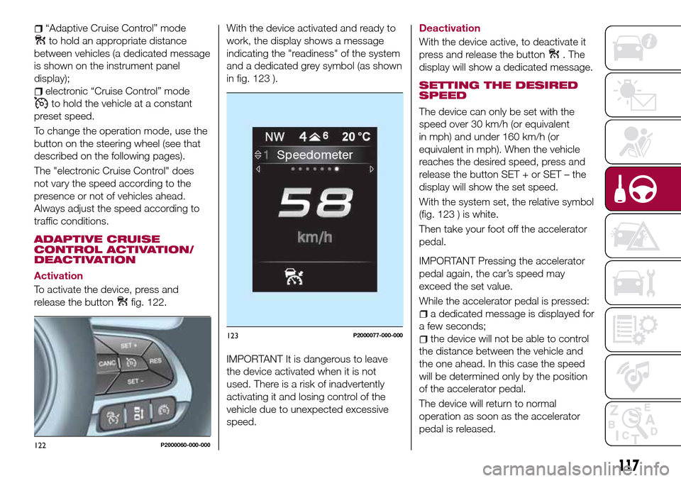
fig. 122.With the device activated and ready to
work, the display shows a message
indicating the "readiness" of the system
and a dedicated grey symbol (as shown
in fig. 123 ).
IMPORTANT It is dangerous to leave
the device activated when it is not
used. There is a risk of inadvertently
activating it and losing control of the
vehicle due to unexpected excessive
speed.
Deactivation
With the device active, to deactivate it
press and release the button
. The
display will show a dedicated message.
SETTING THE DESIRED
SPEED
The device can only be set with the
speed over 30 km/h (or equivalent
in mph) and under 160 km/h (or
equivalent in mph). When the vehicle
reaches the desired speed, press and
release the button SET + or SET – the
display will show the set speed.
With the system set, the relative symbol
(fig. 123 ) is white.
Then take your foot off the accelerator
pedal.
IMPORTANT Pressing the accelerator
pedal again, the car’s speed may
exceed the set value.
While the accelerator pedal is pressed:
a dedicated message is displayed for
a few seconds;
the device will not be able to control
the distance between the vehicle and
the one ahead. In this case the speed
will be determined only by the position
of the accelerator pedal.
The device will return to normal
operation as soon as the accelerator
pedal is released.
122P2000060-000-000
123P2000077-000-000
117